SUNBA Illuminati User manual

2020/06
Illuminati Auto Tracking
Network PTZ Camera
User Manual 2.0
Visit http://autotrack.sunba.net to access the step by step YouTube video
tutorials for setting up Sunba Illuminati.

FCC Warning (U.S.A)
The device has been tested in compliance with limits set by Part 15 of
Federal Communication Commission (Class B). The operation of the
device is thus limited by the following two conditions:
1) it is not permitted to cause harmful interference to any authorized radio
communications, and 2) it must accept any interference it receives.
WARNING: Please test the camera locally by directly connecting
to the default power adapter from the package before mounting
it outside. Stay at least 24 hours to test both daytime and night
vision IR LED.
MENU
1. Model Specification --------------------------------------------------------------
2. Connection and Installation --------------------------------------------------
3. Camera Management ---------------------------------------------------------
3.1 Web Interface ---------------------------------------------------------------
3.2 Client Software ------------------------------------------------------------
3.3 Smartphone app -----------------------------------------------------------
4. Static IP Management --------------------------------------------------------
5. PTZ, Preset and Patrol --------------------------------------------------------
6. The Full Preset List --------------------------------------------------------------
7. Auto Tracking ---------------------------------------------------------------------
8. Remote Access ------------------------------------------------------------------
9. User Management --------------------------------------------------------------
10. Motion Detection --------------------------------------------------------------
11. FTP Communication ----------------------------------------------------------
12. Cable Waterproof Measures -----------------------------------------------
13. ONVIF Integration --------------------------------------------------------------
14. Smartphone Push Notification -------------------------------------------
15. On-Screen-Display ------------------------------------------------------------
16. Reset the Camera -------------------------------------------------------------
17. Warranty ---------------------------------------------------------------------------
01
05
05
05
06
10
13
13
15
16
22
25
26
28
29
30
31
32
34
38
- 01 -
1. Model Specification
Model
Image Sensor
Resolution
Focal Length
Angle of View
Aperture Range
Min. Illumination
Focus
Pan & Tilt
Zoom
Day/Night Mode
Night Vision
Standard
API Interface
Auto Tracking
Audio G.722.1, G.711-a law, G.711-u law, MP2L2, G.726, AAC, PCM
Illuminati
1/2.8” Progressive SONY CMOS
4.8 ~120mm
Auto/Manual/Semi-auto
Optical: 25X Digital: 16X
BW/Color/Auto
Up to 1000ft
ONVIF/ISAPI/SDK
Preset Tracking, Intrusion Tracking, Line Cross Tracking
TCP/IP, HTTP, DHCP, DNS, DDNS, RTP, RTSP, RTMP, PPPoE, SMTP, NTP, UPnP,
SNMP, FTP, 802.1x, QoS, HTTPS, IPv6 (SIP/SRTP)
Pan: 0 ~ 360° Tilt: -15 ~ 90°
57.6 ~ 2.5 Degrees (Wide-angle ~ Telescope)
F1.6 ~ F3.5
50HZ: 25fps (1920×1080) 60HZ: 30fps (1920×1080)
50HZ: 25fps (1280×720) 60HZ: 30fps (1280×720)
Color: 0.05Lux@(F1.6, AGC ON)
B/W: 0.01Lux@(F1.6, AGC ON)
2. Connection and Installation
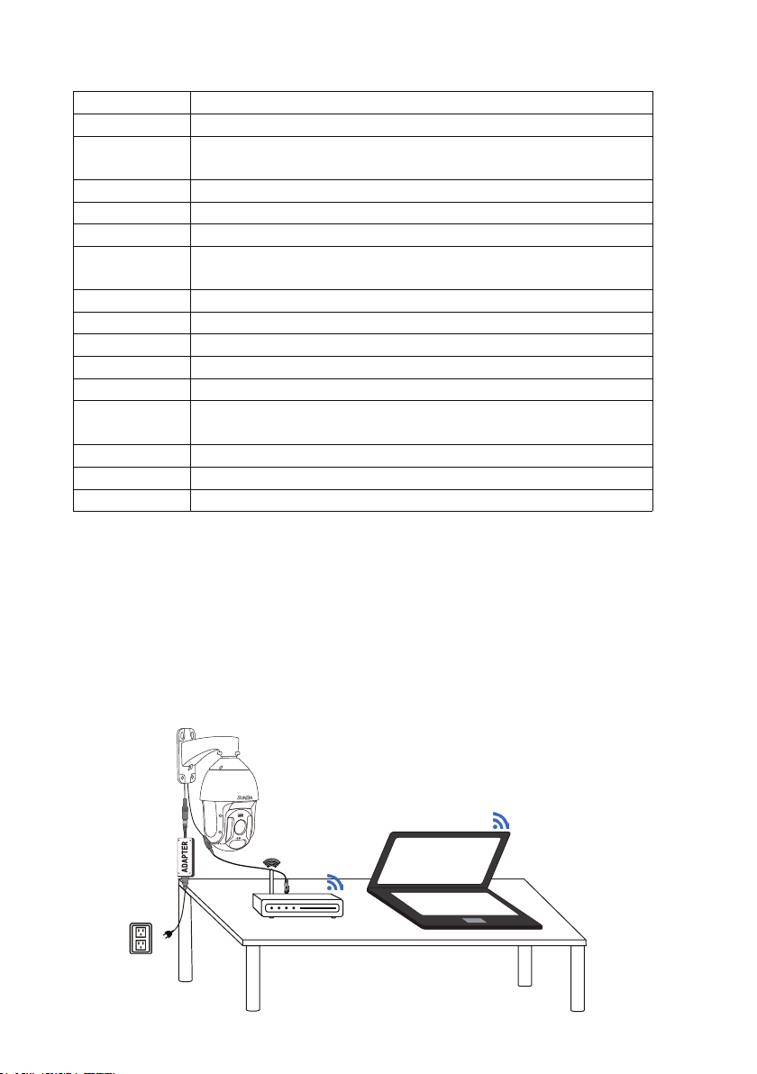
2.1 Indoor Bench Test
Please test the camera properly on the bench for 24/7 before install it
outside. The pre-installing test is so critical to ensure all equipments will
work as expected. This will test network and power tranmission, monitor
day and night video quality, and avoid any potential issues that might
develop when the camera is finally mounted.
Type A: With DC12V Adapter
Adapter
Computer
IP Camera
Router

- 02 -
Do NOT extend the power cable during the bench test because DC power
drops quickly along the transmission. A bench test helps you rule out all
problems caused by power supply. Underpower causes problems such as
1. Ghost image
2. Unstable infrared (camera reboots repeatedly) and
3. Random spinning dome.
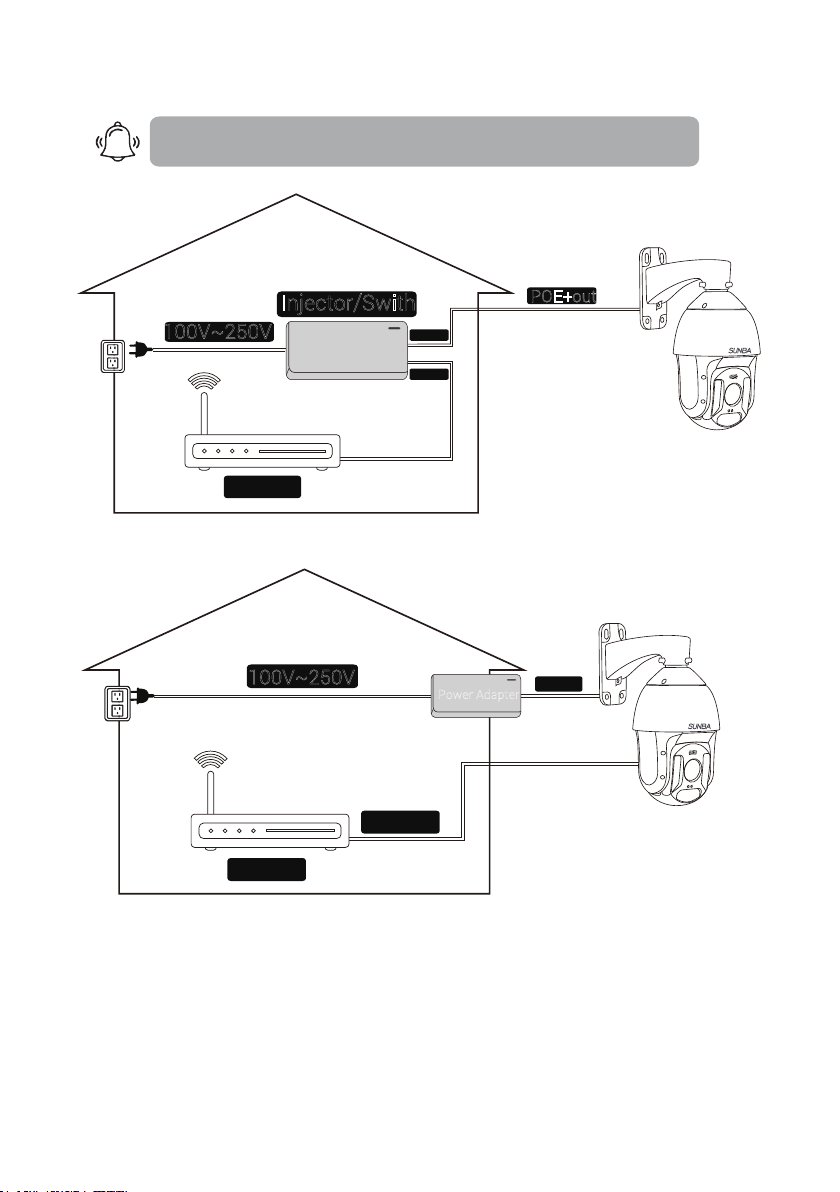
Type B: With PoE+ Injector/Switch
Test the camera on your desk before mounting outside.
IP Camera
Router
Computer
PoE+ Injector
When powered up, the speed dome automatically begins a self-diagnostic
process during which the camera will pan horizontally and vertically to
make sure PTZ, lens and other parts of the camera are functional. Please
contact our technical staff if a self-test does not happen on your unit. Please
refrain from disassembling the unit before contacting us. Thanks for
your cooperation.
Built-in self-test
Connection Good
Power Good
Video and Control Good
Tested Day and Night
Guess we are ready to mount it outside.

- 03 -
2.3 Install the TF Card
Illuminati camera comes with a built-in micro SD card slot that can store
videos and snapshots.
1
Remove the 4 screws to take
off the camera back cover.
Insert the TF card as directed
by the arrow.
2
2.2 PoE+ Requirement
PoE+IEEE 802.3at standard is required. Note traditional PoE system( 802.
3af standard) delivers up to 15.4W, which is unable to fully support the
camera. Dome cameras, especially with 20x zoom-in capacity, have
higher power requirements than fixed cameras.
Transmission distance
PoE will also drop power along the Ethernet cable. With PoE+ adapter supplying
30W, please don’t run Ethernet over 200ft. The maximum travel distance depends
on the quality of the cable and the maximum power supplied by switch/injector.
NVR’s built-in PoE switch
Some NVRs have built-in PoE switches. It is important to check whether each port
can supply at least 25W (with 802.3at) as some of those are for bullet cameras and
can’t supply enough power for PTZ (with 802.3af only).
Biggest issue when underpower
In the daytime, even 802.3af (conventional PoE system) can provide enough power
to the camera. However, in the night time, if you are underpower, the following
problem begins: low light environment detected -> infrared on -> not enough power
-> reboot -> low light environment detected -> infrared on -> not enough power ->
reboot …… (cycling)
- 04 -
The screws and anchors to attach the camera to the installation
environment are not included and please set the appropriate screws
subject to the specific environment such as concrete, wood, dry wall and
bricks.
2.4 Mounting Outdoor
100V~250V
Data in
Router
Non-PoE
ELE (Force Electricity)
Wiring method:
≥18 wire gauge
DC 12V
Power Adapter
Good, the camera is working correctly. Now I just need to pick the right
extension cable and mount it outside!
≥30W
100V~250V Data out
Data in
Router
POE+out
POE+
802.3at
100~200ft
POE+
ELV (Extra-LowVoltageSystem)
Wiring method:
Injector/Swith
Please use Sunba 65W high
power injector if you are runing
over 200ft.
Consider using extension cord to get AC the required distance first, then
use the power adapter. If that’s not possible in your environment, pick a
thicker wire (≥18 AWG) for DC extension or consider running PoE+.

- 05 -
The camera is set to DHCP mode by default, meaning the router will
automatically assign a matching IP to the camera. Therefore, the camera
should be in “online” status once it has been powered and connected to
the router.
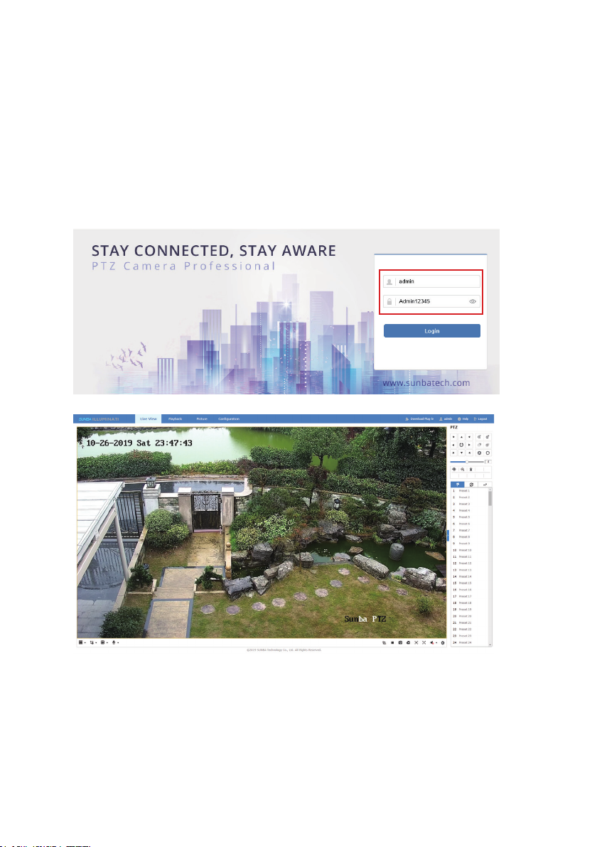
Default Username/Password:
Username: admin
Password: Admin12345
Note: Please pay attention to the capitalized A in the password field.
3. Camera Management
3.1 Camera Management by Web
The following browsers are supported:
Internet Explorer 11 (Windows)
Chrome (Windows)
Firefox (Windows 7)
The first step of accessing the camera via a web browser is to obtain its IP,
which is the url of the camera. The IP scanning tool called SADP is required
to be installed first.
The SADP tool (Mac & Windows) can be retrieved from the CD-ROM or from
Sunba website (under download section: https://sunbatech.com/download/ )
Below is a screenshot of the tool and the “IPv4 Address” column stands for
the IP of the camera.
- 06 -
Next, please open a compatible web browser, and input the IP of the camera
in the address line. For example, for the above camera, please enter
http://192.168.1.12 in the address line. In the future, if the default HTTP port
(80) of the camera has been changed, the url to login the camera through
web interface will be http://IP:HTTP Port
A web plugin must be installed manually for all browsers. The plugin file can
be obtained from Sunba website or from the CD-ROM came with the camera.
In the login page, please input the default username/password of the camera:
3.2 Camera Management by Client Software
Windows: iFollow
Mac: Guarding Vision
The software set can be retrieved from the CD-ROM or from Sunba website
(under download section: https://sunbatech.com/download/ )
Click “Login” to log into the camera.

- 07-
Install and open the software, which will ask you to assign a user for the
iFollow client. Note this is NOT the credential for the camera. The purpose
of creating an account for iFollow client is to avoid unauthorized access to
the surveillance monitor software. Users can also “enable auto-login” to
skip the authentication step every time the software is open.
Next, the client will display all
discoverable online device and
please select a device, and
click “Add to Client” to add the
camera to the Device for
Management.
Users can customize a nickname for the device, enter its
username/password and choose whether to “Synchronize the Device Time”
to the desktop.

- 08 -
Please remember to click “Export to Group”, which is a required step before
users are able to view and configure the camera over the client software.
The purpose of “Group” is to better categorize different cameras in a
surveillance project.
If the “Export to Group” option is not selected when the camera has been
initially added, users can go to “Group” and click “Import” to manually
assign the camera to a group.
In the Import menu, select the camera on the left hand side, and create a
group folder on the right hand side such as “Home”, “Office” or “Sunba” by
the characteristics of cameras for categorizing purpose.
Export to Group
Manually assign the camera to a group
Table of contents
Other SUNBA Security Camera manuals

SUNBA
SUNBA Analog Series User manual

SUNBA
SUNBA FT-HD User manual

SUNBA
SUNBA Network Series User manual

SUNBA
SUNBA 604-22X User manual

SUNBA
SUNBA Network Series User manual

SUNBA
SUNBA 603-D25X 4G User manual

SUNBA
SUNBA 405-D20X User manual

SUNBA
SUNBA 601-D25X 4G/WiFi V2 User manual

SUNBA
SUNBA 603-D25X 4G User manual

SUNBA
SUNBA 502S-AHD User manual


