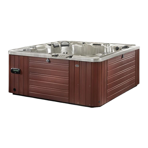
Sunbelt SUPREME User manual

SUPREME STORM WAVE
SB SERIES ULTIMATE
SMARTOUCH DIGITAL
Home Owner’s Manual
60 HZ United States Series
50 HZ European Series

2 | P a g e
TABLE OF CONTENTS
Important Hot Tub Owner Information ............ pg. 3
Important Safety Information............................ pg. 4-5
Installation Requirements ................................. pg. 6
Electrical/Wiring Requirement……………….…..……pg. 7
SmarTouch Setting Instructions......................... pg. 8
SmarTouch Time of Day Instruction .................. pg. 9
The Control Panel.............................................. pg. 10
Device Control Keys........................................... pg. 10
Status Control Keys ........................................... pg 12
Getting To Know Your Spa Components ........... pg. 14
Spa Care Guide.................................................. pg.19
Cleaning the Hot Tub Surface ............................ pg. 19
Maintaining the Hot Tub Cabinet ...................... pg. 20
Chemical Adjustments & Use ............................ pg. 21
Draining Spa & Water Changes.......................... pg. 23
Winterization .................................................... pg. 24
Cover Maintenance ........................................... pg. 25
Error Messages.................................................. pg. 28

3 | P a g e
IMPORTANT HOT TUB OWNER INFORMATION
Sunbelt Spas utilizes the latest in technology to provide you with a hot tub of the highest
quality that is easy to maintain. It is imperative that you read all of the information provided
in your homeowner’s manual and maintains your hot tub utilizing the correct chemicals and
maintenance schedule. The spa surface is made of Lucite Acrylic and must be protected from
direct sunlight by use of the spa cover provided. Exposure of the spa surface and fittings to
direct sunlight or ultraviolet rays may cause damage to the spa’s surface. Exposure will void
warranty to the spa surface and to the fittings. Sunbelt Spas Installation Requirements must
be met by the homeowner including slab and electrical requirements. Any deviation from the
Installation Requirements will result in void of warranty.
Sunbelt Spas strives to provide the best possible hot tub for your use therefore modifications
and enhancements to the hot tub, mechanics, equipment, and structure may be made which
effect the specifications, illustrations, and/or instructions within this manual.
Sunbelt Spas Hot Tubs meet all requirements and regulations of ETL laboratories.
Sunbelt Spas ETL listing is 9901934 and conforms to UL STD 1563 of Electric Hot Tubs, Spas and
Associated Equipment. Further information may be requested from Sunbelt Spas, 3924
Dunvale Rd. Houston, TX 77063.

4 | P a g e
IMPORTANT SAFETY INFORMATION
When installing and using this electrical equipment, basic safety precautions should be
followed. Including the following:
ALWAYS READ AND FOLLOW ALL DIRECTIONS –
WARNING –To reduce risk of injury, do not permit children to use this product unless they are
closely supervised at all times.
DANGER –Risk of accidental drowning. Take extreme caution to prevent unauthorized access
to the spa by children. To avoid accidents ensure that children cannot use the spa unless
supervised at all times.
DANGER –Risk of injury. The suction fittings in this spa are sized to match the specific water
flow created by the pump. Should the need arise to replace the suction fittings or the pump,
be sure that the flow rates are compatible. Never operate the spa if the suctions are broken
or missing.
DANGER –Risk of electrical shock. Install at least 5 feet (1.5m) from all metal surfaces. As an
alternative, a spa may be installed within 5 ft. of a metal surface if each metal surface is
permanently connected by a minimum of No. 8 AWG (8.4 mm2) solid copper conductor to the
terminal box that is provided for this purpose.
DANGER –Risk of electrical shock. Do not permit any electrical appliance, such as light,
telephone, radio, or television, within 5 feet (1.5 m) of a spa.
WARNING –To reduce the risk of injury –
• The water in the spa should never exceed 104 F (40 C). Water temperatures between
100 F (38 C) and 104 F (40 C) are considered safe for a healthy adult.
Lower water temperatures are recommended for younger children and anytime spa use
exceeds 10 minutes.
• Since excessive water temperatures have a high potential for causing fetal damage
during the early months of pregnancy, pregnant or possible pregnant women should limit spa
water temperatures to 100 F (38C).
• Before entering a spa, the user should measure the water temperature with an accurate
thermometer since the tolerance of water temperature regulating devices varies.
• The use of alcohol, drugs or medication before or during spa use may lead to
unconsciousness with the possibility of drowning.
5 | P a g e
• Persons suffering from obesity or with a medical history of heart disease, low or high
blood pressure, circulatory system problems or diabetes should consult a physician before
using a spa.
• Persons using medication should consult a physician before using a spa since some
medication may induce drowsiness while other medication may affect heart rate, blood
pressure, and circulation.
WARNING –Risk of suffocation. On spas with a gas heater the heater must be placed outside
unless proper ventilation can be provided for an indoor installation.
SAVE THESE INSTRUCTIONS!

6 | P a g e
INSTALLATION REQUIREMENTS
Sunbelt Spas manufacturing process uses high quality components that add significant weight
to the spa structure. The combination of the spa weight and the weight of the water filling the
spa make a proper foundation necessary. Improper spa foundation can result in shifting of the
spa structure or shell. Damages to the spa shell, structure, equipment and/or skirting due to
improper foundation will not be covered under warranty.
Proper Spa Foundation –Sunbelt Spas recommendation for proper spa foundation is a
structure that uniformly supports the weight of the hot tub and the water filling the hot tubs.
The surface of the foundation should be smooth, flat and level. We recommend a poured and
steel re-bar reinforced concrete slab, a minimum of 4 inches thick, for all hot tubs sized eight
feet by eight feet and under. Wood decking must be a pier and beam style that properly
supports the spa’s weight.
Sunbelt Spas are produced for use in outdoors. We recommend you do not recess a Sunbelt
Spas hot tub in a hole. Recessing the unit into a hole can cause potential problems with access
and water retention within the hole itself. Every side of the hot tub is removable and must be
accessible for service. Any and all cost of spa removal and replacement, landscaping, decking,
fencing, and/or structure removal, alteration and/or replacement or any other costs of
providing access to the spa will be the responsibility of the purchaser.

7 | P a g e
ELECTRICAL REQUIREMENTS
Electrical Requirements 60 HZ United States Series-
Supreme, Ultimate, Storm, & Wave Series Sunbelt Spas must to be wired as 240V hard
wire system.
For 240V Wiring
Minimum Wire Size –
Four Wire –Two (2) #6 thhn HOT, One (1) #8 thhn NEUTRAL, One (1) #9 thhn
GROUND
Breaker Required –
60 amp Double Pole GFCI Protected Breaker
**This breaker must be dedicated for the spa use ONLY**
For distances over 75’ from the breaker to the spa a larger size wire may be required. A
licensed electrician must evaluate the wiring. When running the wire, remember to leave 10’
of spare wire at the location of the tub in order to be prepared for tub positioning.
IMPORTANT:
The National Electrical Code states that a service disconnect breaker box must be located at
least five feet away from the spa and should be conveniently located near the equipment
bay. If it is not in plain sight, keep the disconnect padlocked when in the off position.
Effective January 1994 GFCI are required for spa installations.

8 | P a g e
IN A HURRY? READ THIS!
For those who don’t like to read manuals or would like to read the manual later, please read at
least the following section.
SmarTouch Digital comes to you with a universal set of default
settings. If you choose to keep these settings, then you only need to
remember 2 things: how to set the spa temperature and to press the
SET key whenever you are done using the spa.
Setting temperature
Press and hold the TEMP key for 2 seconds. Release all keys
oThe display will flash the current selected temperature.
Using the TEMP and TIME keys (UP and DOWN arrows)
oScroll to the desired temperature.
Press the SET key to lock in the new selection
The SET Key
After using the spa, press the SET key to tell the microcontroller you are done using the spas.
It will then take over the spa’s management including the different filtration cycles, heat
maintenance, economy modes and protection against freezing.
Upon entering this mode the FILTER light is turned on and a post use filtration cycle is
executed –that is when the spa needs filtration the most. The default system setting includes
a 3 hour economy mode; the pump will come on at most once every 3 hours to sample water
temperature and heat if necessary. The controller remembers when you have used the spa
and in anticipation of your next usage will perform a 3 hour Auto Filtration cycle before your
next spa use.
SmarTouch Digital Series 1000 and 2000 is a family of intelligent, spa control systems. These
systems are rich with features and can be extensively programmed to fit just about any need.
The rest of this manual will explain the function of each of the keys on the control panel, how
to change programmed settings and what each setting does. It will also explain all the error
messages that you may encounter, and their significance and way to correct them.

9 | P a g e
TIME OF DAY
SmarTouch Digital maintains a 12 hour AM / PM internal real time clock TOD (Time Of Day).
The clock based on the line frequency. There is no battery backup and whenever the power is
turned off, TOD is no longer correct. It defaults to 12:00 AM whenever the power is turned
on.
Setting TOD is only necessary if you are going to program the filtration and silence cycles. If
you use the factory default settings then you do not need to set TOD.
If you set TOD then SmarTouch will display time every first 10 seconds of each minute. If TOD
has not been set then it will not be displayed.
Setting TOD
1. Press and hold the TIME key for 2 seconds. Current TOD will be displayed with
the hour portion flashing.
2. Release the TIME key.
3. Using the TEMP and TIME keys scroll up and down to the desired hour. –Notice
the AM / PM Led.
4. When the correct hour and AM / PM are displayed press the SET key to lock in the
new hour.
5. The display will now flash the minute portion of current TOD.
6. Using TIME and TEMP scroll to the desired minutes.
7. When the correct minutes are displayed press the set key to lock in the time of
day (hours and minutes).
Note: TOD is the only parameter in SmarTouch Digital that is not preserved on power down.
On power up it will default to 12:00 AM, all other parameters are restored to their last setting.
Every time the controller is powered up, the microprocessor automatically measures and
determines whether the line frequency is 50 or 60 cycles in order to maintain the correct TOD.

10 | P a g e
THE CONTROL PANEL
The control panel is normally installed on the lip of the spa for easy and convenient access.
Within the panel housing is a 4 digit LED display used to communicate to the user spa
temperature, TOD, elapsed user time, programming, status –diagnostic and error codes and
messages. There are 2 different size panels. They are interchangeable. The 2000 Series panel
can have up to 7 keys; the 1000 Series panel will have at most 6 keys. These are membrane
type switches which when depressed generate a signal that the microprocessor will interpret
and act upon. The switches are labeled and have specific functions. They are divided into 2
groups:
Device Control Group Pump(s), Air Blower & Spa Light.
Status Control Group: Up & Down Keys & the Set Key.
Note: If any of the keys are pressed and held closed for longer than 20 seconds, that key will
be disabled and becomes non-functional. After releasing the key, it will be re-activated after
20 seconds. This is to prevent a collapsed or defective key from locking up the system.
DEVICE CONTROL KEYS
There are up to 4 device keys, JETS, AIR, AUX & LITE. Your spa will have at least one water
pump. Optionally your spa may have an air blower, a second and/or third pump and a spa
light. It may also have a mister or a fiber optic light setup. If your spa does not have a specific
device please disregard the function of that device.
Primary Water Pump
Each spa should have at least one primary water pump which is usually a dual speed pump.
The low speed is used to filter the spa. Also while the spa is being heated or there is an error
condition, the low speed circulates the water and you will not be able to turn it off.
The JETS key (switch) on the control panel is a 3 position switch:
Low Pump, High Pump, Off. Each time the key is pressed, the next function is executed. If
your primary pump is a single speed pump then only the high pump will be activated. 2 LED
indicators, LO & HI inform you which speed is on.
Note: if your spa is equipped with a circulating pump it will be used for filtration and heating
instead of the low speed pump.

11 | P a g e
Air Blower
If your spa is equipped with an air blower (bubbler), it is activated by the AIR key. This is an
ON/OFF key. An LED will indicate when the air blower is on.
Auxiliary Pump(s)
You spa may be equipped with 1 or 2 more pumps. If you have a second pump, it could be a
single speed or a dual speed.
If you have a third pump then both the second and third pumps must be single speed. The
function of the AUX key changes with the number and type of auxiliary pumps used. Please
consult with the table on the following page for the proper sequence of activation.
Spa Light
The LITE key can also be a multifunction key. In its simplest configuration, the LITE key is a
simple on / off switch. It turns the spa light and the accessory, if one is attached, on / off
switch together at the same time. Alternatively the LITE key may be programmed as a 3
function key. Pressing it once will turn the spa light on. Pressing it a second time will turn on
the attached accessory, while the light is still on. Press it a third time and both spa light and
accessory will go off.
The table below summarizes all the possible device key combinations. Please note that your
spa may not necessarily have all these devices attached.
Table 1 –Device keys summary of functions
SUMMARY OF FUNCTIONS FOR EACH DEVICE
Key Device 1 2 3 4
Single speed pump ON OFF
JETS Dual speed pump LOW HIGH OFF
Dual speed with Circ pump LOW HIGH OFF
Circ pump is independent
AIR Single speed air blower ON OFF
Two single speed pumps P1 P1&2 P2 ALL OFF
Spa light ON OFF
LITE Spa Light & Accessory Both Both
ON OFF
Spa Light & Accessory Lite Both Both
3 Function ON ON OFF

12 | P a g e
The four device keys, JETS, AIR, AUX and LITE are exclusive, when one is pressed, no other key
may be pressed simultaneously. You must release the pressed key before you may press
another key. Also these keys do not repeat.
If you press and hold a key for more than 20 seconds that key will be considered defective
(collapsed) and will be deactivated and ignored by the system. When released, the key will
stay inactive for 20 seconds before it is recognized and activated.
STATUS CONTROL KEYS
The keys in this group are used to communicate to the controller systems settings and option
selections(s). There are 3 keys in this group and 3 functions that are combinations of these
keys:
Table 2 –Status Control Keys Summary
The TEMP key, which is also the UP ARROW key, is a repeat key if held down. Think of this key
as “+ or next”. Use it to:
Press and hold for 2 seconds then release it to start desired temperature selection.
During temperature setting press TEMP to increase selected temperature.
When doing system programming press TEMP to scroll to the next message.
After message selection, the system displays the associated value, press TEMP to
increase that value.
Note: when the display is inverted, you will be able to read the display from inside
the spa; the keys will retain their functions and will not be inverted. The UP ARROW
will still function as the UP ARROW even though when you look at it from within the
spa it appears to be the DOWN ARROW. The same also applies to the rest of the keys.
Key Press Function
TEMP (up arrow) Prog Temp, + or Next
TIME (down arrow) Prog TOD, - or Previous
SET key Select or Accept, Enter
SET & TEMP Invert display
SET & TIME Parameter programming
TEMP & TIME System programming

13 | P a g e
The TIME key, which is also the DOWN ARROW key, is also a repeat key. Think of it as
“-or previous”. Use it to:
Press and hold for 2 seconds then release it to start setting the real time clock (TOD).
During time setting press TIME to decrease the hours or minutes value that is being set.
When doing system programming press TIME to scroll to the previous message.
After selecting a message, the system displays the associated value, press TIME to
decrease that value.
The SET key is equivalent to Select of Accept. It functions as an Enter key of a personal
computer; it is the proverbial “hit any key to continue”. Press the set key to:
After using the spa press the SET key to tell the controller to take over the management
of the spa.
During temperature setting press the SET key to lock in a new selected temperature.
During time of day programming press the SET key to lock in the hour and the minutes.
When a message is displayed during parameter programming, press SET to select that
message.
When a parameter value is displayed, press SET to accept the displayed value and return
to message display.
During option programming press SET to toggle a parameter ON or OFF.
When a “HLoH” error message is displayed press the SET key to clear the error (if the
cause has been corrected). Pressing the SET KEY, the user acknowledges that the cause
of the hi limit error has been or will be corrected.
Note: UP is synonymous with TEMP and DOWN is the same key as TIME. These are used
interchangeably and mean the same thing. To scroll means pushing either the UP or the
DOWN key to go to the next or previous item or value.

14 | P a g e
GETTING TO KNOW YOUR
SPA COMPONENTS
Your Sunbelt Spa is made with the highest quality components in order to provide you with
the ultimate hot tub. It is important to know the components and operation procedures for
your components. NOTE- Some components are optional and will not be located in your spa.
ACC –Control Pack & Top Side Control
Water Pump –
The water pump pictured here pushes the water
from the spa through your jets. Pumps operate
through the spa pack ( ) button and have two
speeds.

15 | P a g e
Water Jets –
Bearlingless Massage Sunblaster Jets (5”, 4”, 3”, 2”)
The jets pictured above can be found on a Sunbelt
Spa. Water comes through the jet when the jet is
turned clockwise or into the on position. Water will
be blocked by turning the jet off by twisting it
counterclockwise. When the jet face needs to be
removed the jet can be turned further
counterclockwise and the jet face will pop out of the jet body. When replacing a jet face look
for the small notch in the groove found on the back of the jet. This notch should be positioned
at the identical recess in the jet body when placing the jet. Turning the jet clockwise into the
body will then correctly place the jet into the spa.
Shut Off Valve/Slice Valve –
The shut off valve is a slice valve that stops water
flow from the pump to the attached pipes. In the
up position the slice valve allows for complete
water flow and spa operation. In the down position
the slice valve closes and the water is stopped from
flowing. These slice valves allow a spa technician to
remove the pump and replace the pump without
having to empty all of the spa water.
Air Pump/Blower–
The blower, air pump, pushes air through the
lines and adds air to the air injectors for the
“Bubble” effects in your spa. The air blower is
operated through the spa pack ( ) button and has
one speed.

16 | P a g e
Air Control Knob –
The air control knob is a valve that allows the passage of air into
the jets. This knob operates by turning the knob to the on position,
clockwise, and the off position, counterclockwise. The air control
knob will affect the strength of the jets and can be changed to
personal preference.
Air Injector –
The air injector is where the air
blower pushes air into the spa
creating the “Bubble” effect
throughout the spa. These air
injectors can be infused with various
aromas if the aromatherapy option
is placed on the spa.
Aromatherapy Canister –
The aromatherapy canister holds a sachet of aromatherapy beads.
There are multiple scents available for the aromatherapy beads and
your dealer can provide them. This canister is in line with the air
blower and each time the blower is turned on the aroma is infused
into the air injectors.
Skim Filter System –
The skim filter is the most effective filtration system available
in a portable spa. The skim filter works by the water flowing
over highly efficient filters when the spa control pack operates
the filter cycle.

17 | P a g e
To remove the filters simply slide the filter cover up and
off of the filter.
Remove the filter skim basket that is designed to catch
larger objects prior to them reaching the filter.
Reach in and remove the filter. Note –Some filters have
screw mechanisms and need to be spun
counterclockwise to remove the filter. Many filters are
stacked to increase the filtration of the spa so check to make sure all filters are removed.
When placing the filters back make sure to spin the filters into place then replace the filter
skim basket and slide on the filter cover.
Ozonator –
The Ozonator, long black tube or white rectangular box pictured
above, produces O3 molecules that are released into the water.
These molecules enter the spa water through the ozone injector jet
and help to kill bacteria and most unicellular microorganisms. This
option helps you maintain your Sunbelt Spa and utilize fewer
chemicals. The Ozonator will operate each time the spa filtration
functions are in service.
Ozone Injector Jet –
The ozone injection jet is the vessel in which the O3 molecules are placed into the water and
release tiny O3 bubbles during operation.
Waterfall –
The waterfall option of a Sunbelt Spa creates a visual
wall of water while providing auditory enjoyment. A
cascading wall of water emits from the horizontal slit in
the waterfall. The waterfall function can be operated by
the on/off valve while the pump button is in the on
position. See picture below.

18 | P a g e
On /Off Valve/Waterfall Valve -
The on/off valve or waterfall valve, 1” valve above, operates
the waterfall option of the Sunbelt Spa. Turning the knob
clockwise will activate the waterfall and turning the knob
counterclockwise will eliminate the waterfall action.
Remember the waterfall valve works throughout the range
allowed by the knob so it is possible to operate the waterfall
at a custom level of power.
Footdome –
The Footdome of Sunbelt Spas is an available option on
some Sunbelt Spas. The jets located in the Footdome
operate by producing a volcanic effect in the footwell of
the spa. The jets can be turned to increase and decrease
the flow of water to the Footdome and the surrounding
seats by using the Diverter Valve. See picture below.
Diverter Valve –
The diverter valve operates the Footdome and seating areas in
some spas. The knob operates by increasing the water flow to
the Footdome and decreasing the flow to the seating area or
decreasing the flow to the Footdome and increasing the flow to
the seating area.
Drain Plug –
The drain plug, pictured above, allow you to
drain your hot tub of water. It works by twisting
the Drain Plug Water Hose Adapter onto your
water hose. Screw the Drain Plug Hose Adapter
into the Drain Plug and the water will flow out of
the water hose

19 | P a g e
SPA CARE GUIDE
Regular Schedule Maintenance
The following section is a listing of the regular scheduled maintenance items you should
complete to keep your spa working well.
Testing Your Water - Minimum 2-3 Times A Week
Test the spa water by placing a test strip into the water according to manufactures
instructions. Read the results and increase and decrease your chemicals according to the
findings on your test strip.
Filtration Cleaning - 2 Week Intervals
Turn off your breaker so the filter cycle will not activate while cleaning. The filter is
located inside the skimmer. The skimmer faceplate will slide up and off. The basket
inside should be pulled out, any debris removed and rinsed off. The filter cartridge
should be removed by turning the filter cartridge in a counter-clockwise direction. It can
be pulled out of the skimmer. *Note* Some filters are side by side models and some are
stacked on top of one another so make sure you get all the filters out.
Using a regular garden hose with a spray nozzle, rinse filter until clean. Every few
months it may be necessary to soak the filter in a cleaning solution. Make sure it is a
filter cleaner designed for hot tub use as soaps often leave residue that creates bubbles
and problems with your spa components. After soaking in a filter cleaner spray the
filters making sure to remove all the solution before replacing into the filter.
Replace the filter. Insert the filter into the skimmer and turn clockwise until snug. Slide
the basket back into place. Slide the faceplate onto the skimmer and be sure the
skimmer door is in place.
Turn the breaker back on.
Cleaning The Hot Tub Surface - As Needed
The surface of your spa is Lucite Cast Acrylic. This is a hard, non-porous surface that prevents
dirt from accumulating and resists stains.
For normal care –Use a soft cloth or sponge with soap and water making sure that the
soap is not introduced into the spa water. Rinse well and dry with a soft, clean cloth. If
using a household cleaner make sure it is recommended by the manufacturer.

20 | P a g e
For dust and/or dry dirt –Use a soft clean damp cloth and wipe.
For grease, oil, paint and ink stains –Use isopropyl (rubbing) alcohol. Rinse well with a
dry soft clean cloth.
For small scratches –Buff lightly with a clean cloth and use either an automotive
polishing liquid or toothpaste containing a fine polishing ingredient.
For deep scratches –sand the surface lightly with 600 grit “wet or dry” paper and buff
with a fine polishing compound.
Make sure never to allow your spa to come into contact with –abrasive cleaners, nail polish,
nail polish remover, wintergreen oil, dry cleaning solutions, lacquer thinners, gasoline, pine oil
and similar items.
Maintaining The Hot Tub Cabinet - As Needed
Regular surface cleaning with a damp cloth will be adequate for most installations and
keep the Synthetic cabinet looking its best.
Stubborn surface stains and accumulation can be removed using a mild soap or
detergent with a soft clean cloth. Household stains, food, body oils and airborne
contaminants will be removed using the mild soap as well.
Make sure not to use any kind of solvent on Synthetic Cabinets. Clean any chemical
spills immediately including, suntan lotion, bug spray and household chemicals. Do not
attempt to clean the surface with abrasive, oil-based cleaners, furniture polish or wax,
or any prepared cleaning solution other than soap or detergent and water.
Synthetic can be scratched but normal scratches from wear and tear will become less
noticeable as Synthetic weathers to a matte finish in the first year of outdoor use.
Minor scratches can be repaired by gently rubbing the affected area with fine steel wool
or extremely fine grit (600) sandpaper then buffing with a soft cloth.
Heavier scratches can be filled using a common furniture scratch repair pencil available
at most home building centers. Examples include; Pain Pal Putty Pencil, Minmax Blend
and Fil Pencil.
This manual suits for next models
4
Table of contents
Popular Hot Tub manuals by other brands

Aquatic
Aquatic SUNSET AI6036R specification

Kogan
Kogan KASPAMSDLTA user guide

Canadian Spa
Canadian Spa St Lawrence 16' Swim Spa KS-10006 user manual

American Standard
American Standard SAVONA 2901.028 SERIES parts list

decina
decina Dolce Vita Installation & owners guide

Jacuzzi
Jacuzzi Mito 5 Specification sheet