The Brighter Choice
IMPORTANT
WARNING
To reduce the risk of fire, electric shock or injury to people:
•Installation should be performed by a professional, qualified electrician familiar with
the construction and operation of this product and the hazards involved.
•Abide by related regional and local laws or regulations.
•Proper grounding is required to ensure safety.
•Check for damage during shipping prior to install. If the product is damaged, do not use it.
•Turn off the switch and circuit breaker before installing this on the LED light fixture.
•To ensure efficient light, regularly clean the light panel. Do not clean with harsh solvents.
•Wipe sensor lens gently with soft cloth to clean. Do not use harsh solvents or scratch lens.
•Use safety precautions. Safety eyeglasses and gloves are recommended.
•Please review instructions carefully before proceeding.
FACTORY DEFAULT SETTING:
100% Detection Area (sensitivity). 5-second Hold ON Time.
Daylight Threshold is disabled. 10% Standby Dimming Light Level. 0s Standby Time.
SETTING CONFIRMATION:
Setting changes made via DIP switch will be confirmed by the light turning on/off.
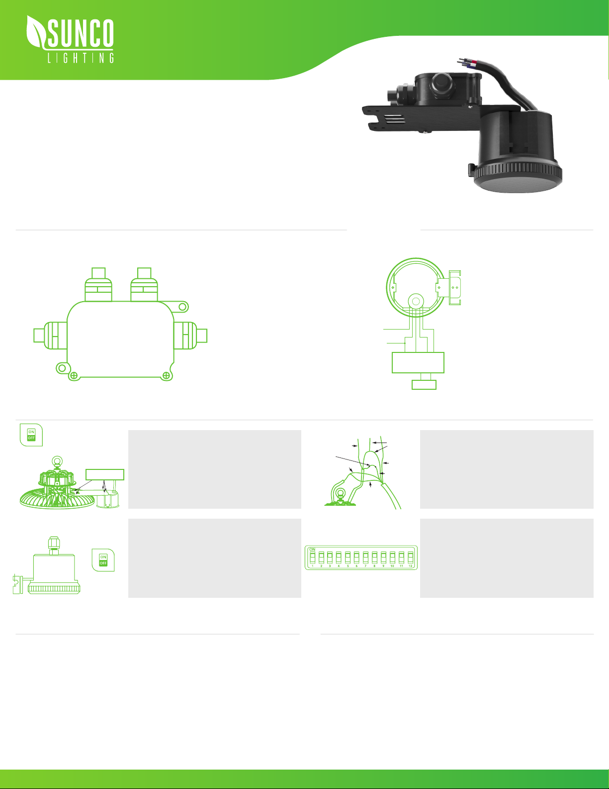
MICROWAVE SENSOR FOR
UFO HIGH BAYS
Install Guide and Manual
1.
2.
4.
5.
3.
Turn off power at fuse or circuit breaker before
installing or servicing.
• If you are working with an existing fixture,
allow fixture to cool before installing sensor.
Secure sensor and bracket onto fixture with
5x provided screws.
Check sensor operation and adjust settings.
• DIP switch access is on side of sensor.
• Open access flap and refer to PARAMETER
instructions to customize settings to suit
your application
Turn on power and test sensor. Adjust parameters,
as needed.
Referring to WIRING DIAGRAM, connect the line
voltage and load wires to sensor leads. Cap with
wire nuts.
•If not connecting a dimmer, cap wires DIM (+) and
DIM (-) with wire nuts.
SETTING DIP SWITCH PARAMETERS
1
2 | 3 | 4
5 | 6 | 7
8 | 9 | 10
11 | 12
Refer to SENSITIVITY section for how to
adjust settings.
- Set Detection Area
- Set Hold Time
- Set Lux
- Set Standby Time
- Set Standby Dimming Level Level
EASY INSTALLATION
WIRING DIAGRAMS Required Tools: Screwdriver, Ladder, Cutters, Pliers.
External Mounting
IN/OUT Details
1. Sensor Input
2. External Input
3. Driver Dimming
4. Driver Input
Brown L
Blue N
Yellow L
Black -
Red +
Sensor Wiring
Turn Power OFF
L
1
3 4
2
N
Turn Power ON
N L 1-10V
+ -
1-10V LED Driver
Load
5x Screws
GND
Ground Green Neutral
White
Line Black
Line Black
Switch Line
Red
N L
Purple
DIM (+)
Gray
DIM (-)


