2SUNFAR E300 SERIES
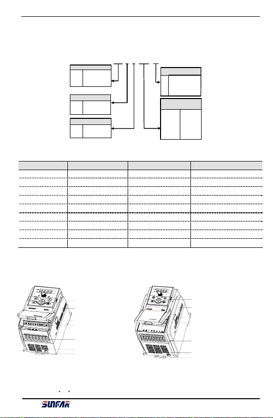
1.4 Specification Data
E300 series power range:2S0002(B) ~2S0022(B) and 4T0007(B) ~4T0037(B).
E300 series specification data and typical functions:
Rated volt and freq 3 PH(4T****)380V
50/60 Hz
1 PH(2S****)220V
50/60 Hz
Input
Permissible volt range 320V ~ 460V 170V ~ 270V
Volt 0 ~ 380V 0~220V
Freq 0~1000 Hz
Output
Overload Endurance 110% for long-term;150% for 1m;180% for 2s
Control Mode V/F control
Analog Input 0.4% of maximum output freq
Freq setting
Resolution Digital Input 0.1 Hz
Analog Input Within 0.4% of maximum output freq
Freq Precision Digital Input Within 0.1% of setting freq
Torque boost Manual set: 0.0~20.0% of rated output
Control
Characteri-
stics
V/F
control
Auto
current/volt
limit
It will check motor stator current and volt
automatically based on special arithmetic to control
within allowable range to ensure minimum failure
during acc/ dec or stable running.
Multi-speed control Seven programmable multi-speed control, three
multi-speed control terminal
RS485 communication
(E300B series)
Standard built-in RS485 interface, RS485
communication protocol and MODBUS for choice
Analog input Panel potentiometer setting, DC volt 0~10V,DC
current 0~20mA
Freq setting
Digital input Operation panel setting,RS485 interface setting,
UP/DW terminal control
Relay and OC
output
One OC output and one relay output (TA, TB, TC)
as many as 9 types for choice
Output Signal
Analog output One 0~10V volt signal
Acc /dec time setting 0.1~600s continuous setting, S curve and linear
mode for choice
DC braking Action freq 0~500.0 Hz, action time 0~20.0 S
Low noise running Carrier wave freq 1.5 KHz ~ 12.0 KHz continuous
adjustment to ensure the lowest motor noise.
Typical
Function
Running function
Upper and Lower freq setting, reversal operating
restriction, RS485 communication,, freq increasing /
decreasing control etc.
Running state Output freq, current and volt,motor rotate speed,
freq setting, module temperature, analog I/O
Display Operation panel
display
Warning
Last four times failure record, output freq, current,
volt and DC volt of last fault trip for running
parameter record
Protection / warning function Over current,over volt, under volt, overheating,
short circuit etc.
E300 Series Mini-type Integrated Universal Inverter Manual


 User manual")