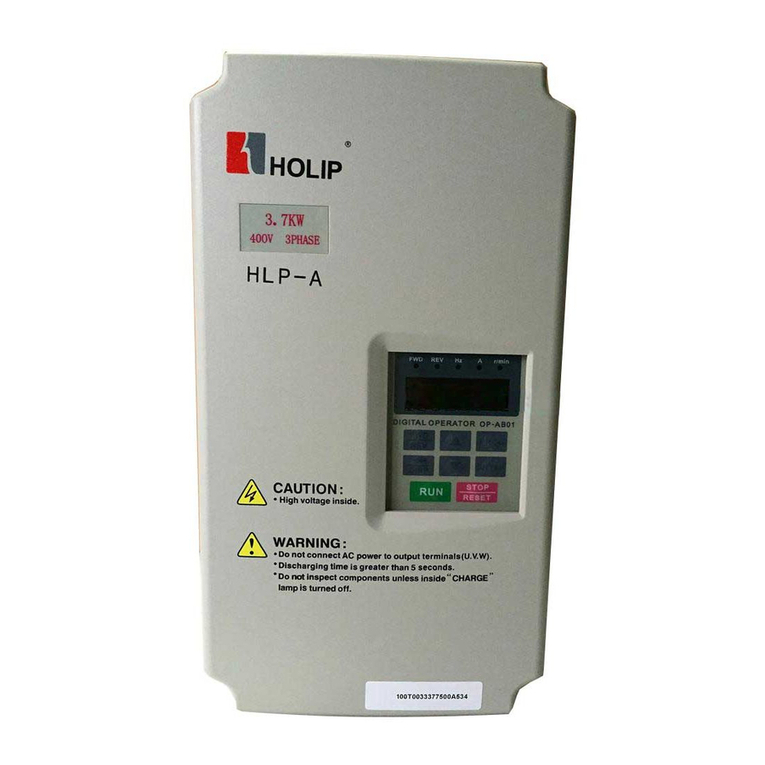
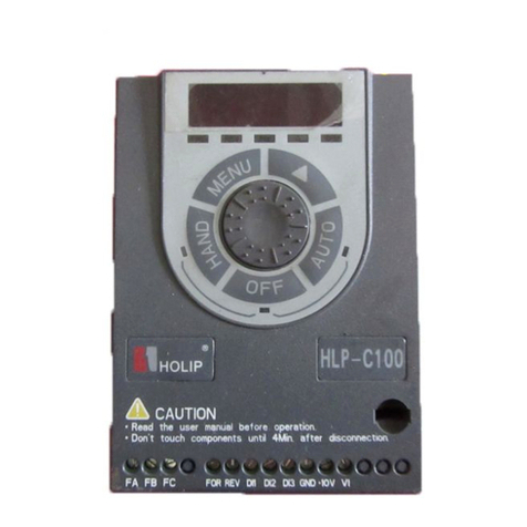
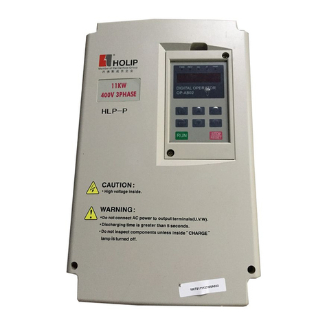
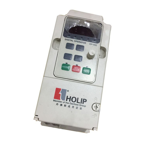
Holip HLP-SV Series User manual

Inverter
1
HLP-SV Series
User’s Manual

Inverter
3
. Introduction...............................................................................4
1. Checks upon Delivery......................................................................................................5
2. Nameplate Description of HLP–SV Series Inverter......................................................5
Ⅱ. Safety Precautions....................................................................7
1. Before the Power-up.......................................................................................................7
2. During the Power-up.......................................................................................................8
3. During the Operation ......................................................................................................8
Ⅲ. Standards andSpecifications.................................................10
1. Particular Specifications................................................................................................10
2. GeneralSpecifications...................................................................................................11
Ⅳ. StorageandInstallation........................................................13
1. Storage...........................................................................................................................13
2. Installation Site and Environment................................................................................13
3. Installation and Direction..............................................................................................13
Ⅴ. Wiring.....................................................................................14
1. Main Circuit Wiring Schematic Diagram ......................................................................14
2. Description of TerminalBlock.......................................................................................15
3. Basic Connection Diagram............................................................................................17
4. Switches .........................................................................................................................17
5. Precautions on Wiring...................................................................................................18
Ⅵ. Instruction of theLCP DigitalOperator................................20
1. Description of the LCPDigitalOperator.......................................................................20
2. Programming with LCP..................................................................................................20
VII. Parameter Overview............................................................23
VIII. Parameter Descriptions.....................................................32
Ⅹ. Maintenance, FaultInformation andTroubleshooting..........79
1. Precautions about Inspection and Maintenance ................................................ 80
2. PeriodicalInspection and Maintenance items.................................................... 80
3. Fault Indication and Troubleshooting............................................................... 80
IX. Appendices............................................................................82
Appendix 1:MountingDimensions of HOLIPSV inverters.............................................82
Appendix 2:MountingDimensions of LCPDigitaloperator ...........................................83
Appendix 3:User’sfeedback..............................................................................................84

Inverter
4
. Introduction
Thankyouforpurchasingandusingthegeneral-purposeinverterof HLP–SVseriesof multi-functionsand
highperformance.
Pleasereadcarefullytheoperationmanualbeforeputtingtheinvertertousesoastocorrectlyinstall and
operatetheinverter,givefull playtoits functionsand ensurethesafety.Pleasekeeptheoperationmanual
handyfor futurereference,maintenance, inspection and repair.
Duetotheinverterofakindofelectricaland electronicproductit mustbeinstalled,testedandadjusted
withparameters byspecializedengineeringpersonsofmotors.
Themarksofand othersymbols inthemanualremindyouof thesafety
and preventioncautionsduringthehandling,installation,runningandinspection.Pleasefollow these
instructionstomakesurethesafe useof theinverter.In caseof anydoubt pleasecontactourlocalagentfor
consultation. Ourprofessional persons arewillingandreadytoserveyou.
Themanual is subject tochangewithoutnotice.
Dangerindicates wrongusemaykill or injurepeople.
Cautionindicateswrongusemaydamagetheinverterormechanical system.
~Danger
lBesuretoturnoff theinputpower supplybeforewiring.
lDonottouchanyinternalelectricalcircuit orcomponentwhenthecharginglamp is still onafterthe
ACpower supplyis disconnected,whichmeans theinverter still has highvoltageinsideand it is very
dangerous.
lDonotcheckcomponents andsignals onthecircuit boards duringtheoperation.
lDonotdissembleormodifyanyinternalconnectingcord,wiringorcomponentoftheinverterby
yourself.
lBesuretomakecorrectgroundconnectionof theearthterminal oftheinverter.
lNeverremodelit orexchangecontrolboardsandcomponentsbyyourself.It mayexposeyoutoan
electrical shockor explosion, etc.
Caution
lMotoroverload protectionis included in thedefault settings. Parameter 1-90 Motorthermal protection isset
tovalue ETR trip.
lDonotmakeanyvoltage-withstandingtest withanycomponentinsidetheinverter.These
semi-conductor parts aresubject tothedamageofhighvoltage.
lNever connect theACmaincircuit power supplytotheoutput terminals U.VWoftheinverter.
lThemainelectriccircuit boardsofCMOSandICoftheinverteraresubjecttotheeffectanddamage
of staticelectricity. Don’t touchthemaincircuit boards.
lInstallation, testingand maintenance must beperformedbyqualifiedprofessionalpersonnel.
lTheinverter shouldbediscardedas industrial waste. It is forbiddentoburnit.
!
~Danger Caution
!

Inverter
5
1. Checks upon Delivery
Theinverterhas beenstrictlyandwell packedbeforeex-work. Inconsiderationof various factors duringthe
transportationspecialattentionshouldbepaidtothefollowing pointsbeforetheassemblyandinstallation.
If thereis anythingabnormalpleasenotify thedealer or therelevantpeopleof our company.
lCheckiftheinverterhas got anydamageor deformationduringthetransportationandhandling.
lCheckifthereis onepiece ofHLP-SVseriesinverterandonecopyoftheinstructionmanualavailable
whenunpackingit.
lChecktheinformationonthenameplatetosee ifthespecificationsmeetyour order (Operatingvoltage
and KVAvalue).
lCheckifthereis somethingwrongwiththeinner parts, wiring andcircuit board.
lCheckifeachterminal is tightlylockedandifthereis any foreignarticleinsidetheinverter.
lCheckiftheoperator buttons areall right.
lCheckiftheoptional components youorderedarecontained.
lCheckifthereis acertificateof qualificationand awarrantycard.
2. NameplateDescription ofHLP –SV Series Inverter
HLP-SV
T/C:HLPSV0D7523A
P/N: 3002102 S/N:010000-466
0.75KW1HP
IN:3×200-240V50/60HZ11.6A
OUT:3×0-Vin0-400HZ4.2A
CHASSIS:IP20 Temp 40℃/104oF
c/n:
O/N:WWW00022165MADE IN P.R.C
CAUTION
SEE MANUAL
WARNING
STORED CHARGE DO NOT TOUCH UNTIL 4
MIN.AFTER DISCONNECTION
RISK OF ELECTRIC SHOCK-DUALSUPPLY
DISCONNECTMAINSAND LOADSHARING
BEFORE SERVICE

Inverter
6
`
VoltageRating:21: 1-PhaseAC 220V
23: 3-PhaseAC 220V
43: 3-PhaseAC 380V
Model:HLP SV 0D75 23 A
Serial No:SVmeansSVseries
TradeMark
Inverter Capacity:0 D 75 means 0.75KW
SoftwareVersion:A

Inverter
7
•. Safety Precautions
1. Before thePower-up
Caution
lChecktobesurethatthevoltageofthemaincircuit ACpowersupplymatchestheinput
voltageof theinverter.
lThesymbol, E,represents groundterminals. Besuretomakecorrectgroundconnection
of theearthterminals of themotor andtheinverter for safety.
lNocontactorshouldbeinstalledbetweenthepowersupplyandtheinvertertobeusedfor
starting or stoppingoftheinverter. Otherwiseit will affecttheservice life oftheinverter.
Danger
lL1 L2L3 terminals arepower input terminals, nevermixedwithU.V.Wterminals. Besurethat
thewiringof themaincircuit is correct. Otherwiseit willcausedamagesof theinverterwhen
thepower is appliedtoit.
lTheterminalofEmust begroundedseparatelyand neverconnectedtolinezero.
Otherwiseit will easilycausetheprotectionor errors of theinverter.
Caution
lDonotcarrythefrontcoveroftheinverterdirectlywhenhandling.Itshouldbehandledwith
thebasetoprevent thefall-offofthefrontcoverandavoidthedropping oftheinverter,which
maypossiblycausetheinjuries topeopleandthedamagestotheinverter.
lMount theinverteronametal or other noncombustiblematerial toavoidtheriskoffire.
lInstall theinverterinasafe location,avoidinghigh temperature,directsunlight, humidair or
water.
lKeeptheinverter fromthereachofchildrenor personsnot concerned.
lTheinvertercanonlybeusedattheplacesaccreditedbyourcompany.Anyunauthorized
workingenvironment mayhavetherisksoffire,gasexplosion,electricshockandother
incidents.
lInstall aheatsink orothercoolingdevicewheninstallingmorethanoneinverterinthesame
enclosuresothatthetemperatureinsidetheenclosurebekeptbelow 40℃toavoidoverheat
or theriskoffire.
lBesuretoturnoffthepowersupplybeforedissemblingorassemblingtheoperation keypanel
and fixingthefront cover toavoidbadcontactcausingfaults ornon-displayoftheoperator.
lDonot install theinverter inaspace withexplosivegas to avoidtheriskof explosion.
lIf theinverter is usedat or above1000maboveseal level,thecoolingefficiencywillbeworse,
sopleaserunit byde-rating.
lDonotinstall anycontactorandothercomponents ofcapacitor or varistoron theoutputside
oftheinverter.Otherwiseit willcausemalfunctionsanddamagesofcomponents ofthe
inverter.
lDonotinstall anyswitchcomponent likeair circuit breakerorcontactorattheoutputof the
inverter.Ifanyof suchcomponentsmustbeinstalledbecauseoftherequirementsofprocess
and others, it must beensuredthattheinverterhasnooutputwhentheswitchacts. In addition,
!
!

Inverter
8
it is forbiddentoinstall any capacitorforimprovement of powerfactororany varistoragainst
thunder at theoutput. Otherwiseit will causemalfunctions, trippingprotectionanddamagesof
components oftheinverter. Pleaseremovethemas shown inthebelow diagram.
lItwill affecttheservice life oftheinverterifacontactis connectedtothefrontendof inputof
theinvertertocontrolits starts andstops. Generallyitis requiredto control it throughControl
terminals. Special attention shouldbepaidtoits useinthecaseoffrequent starts andstops.
lPleaseuseanindependentpowersupplyfortheinverter.Doavoidusingthecommon power
supplywithanelectricalwelderandotherequipment withstrongdisturbance.Otherwiseit
will causetheprotectionor evendamageoftheinverter.
2. Duringthe Power-up
Danger
lDonotplugtheconnectors oftheinverterduringthepowerup toavoidany surgeintothemain
control boardduetoplugging, whichmight causethedamageof theinverter.
lAlways havetheprotectivecover inplacebeforethepower uptoavoidelectrical shockinjury.
3. DuringtheOperation
Danger
lNeverconnectordisconnectthemotorsetwhiletheinverteris inrunning.Otherwiseit will
causeover-current tripandevenburnup themaincircuit of theinverter.
lNeverremovethefrontcoverof theinverterwhiletheinverteris powereduptoavoidany
injuryofelectricshock.
lDonotcomeclosetothemachinewhenthefault restart functionis usedtoavoidanything
unexpected. Themotormayautomaticallyrestart after its stop.
lThefunction ofSTOPSwitchis onlyvalidaftersetting,whichis differentwiththeuseof
emergent stopswitch. Pleasepayattentiontoit whenusingit.
U
InverterV
W
M
KM
X
X

Inverter
9
Caution
lTouchingthe electricalpartsmay be fatal - evenaftertheequipment has beendisconnected from
mains.Alsomake sure that othervoltageinputshave been disconnected,(linkageofDCintermediate
circuit).
lBe aware that theremay be high voltage on the DClink evenwhen the LEDsare turnedoff.
lBefore touching any potentially live parts of the VLTMicro,wait atleastas follows:
200 -240 V,0.4– 1.5 kW:wait at least4 minutes.
380 -480 V,0.75–2.2 kW:wait at least 4minutes.
Shorter timeisallowedonly if indicatedonthe nameplate forthe specificunit.
!

Inverter
10
•. StandardsandSpecifications
1. Particular Specifications
Product OrderModelInputVoltage Power
(KW)
Inverter
Capacity
(KVA)
Output
Current
(A)
Suitable
Motor
(KW)
30002101 HLPSV00D421A 1×200-240V50/60Hz 0.41.02.50.4
30002102 HLPSV0D7521A 1×200-240V50/60Hz
0.752.04.20.75
30002103 HLPSV01D521A 1
×
200-240V50/60Hz
1.52.86.81.5
** HLPSV02D221A 1
×
200-240V50/60Hz
2.2** ** 2.2
** HLPSV03D721A 1×200-240V50/60Hz
3.7** ** 3.7
30002301 HLPSV00D423A 3×200-240V50/60Hz 0.41.02.50.4
30002302 HLPSV0D7523A 3
×
200-240V50/60Hz
0.752.04.20.75
30002303 HLPSV01D523A 3
×
200-240V50/60Hz
1.52.86.81.5
** HLPSV02D223A 3×200-240V50/60Hz
2.2 ** ** 2.2
** HLPSV03D723A 3×200-240V50/60Hz
3.7 ** ** 3.7
30004302 HLPSV0D7543A 3
×
380-480V50/60Hz
0.752.22.20.75
30004303 HLPSV01D543A 3×380-480V50/60Hz 1.53.23.71.5
30004304 HLPSV02D243A 3×380-480V50/60Hz 2.24.05.32.2
** HLPSV03D743A 3
×
380-480V50/60Hz
3.7 ** ** 3.7
** HLPSV05D543A 3×380-480V50/60Hz 5.5 ** ** 5.5
** HLPSV07D543A 3×380-480V50/60Hz 7.5 ** ** 7.5
** These dimensions will be announced at a laterpoint.
This manual suits for next models
25
Other Holip Inverter manuals
Popular Inverter manuals by other brands

MGE UPS Systems
MGE UPS Systems 3.5 to 21 kVA N+1 owner's manual

Generac Power Systems
Generac Power Systems MD1000GEM overview

Falco Systems
Falco Systems WMA-IB-LN user manual

TECO-Westinghouse Motor
TECO-Westinghouse Motor Teco MA7200 Plus Quick start manual

Axpert
Axpert MKS III user manual

Grundfos
Grundfos Solar 15-80 130 Installation and operation instruction