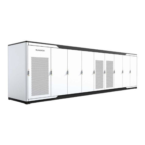
Sungrow PowerStack-ST570kWh-250kW-2h-US User guide

PowerStack-
ST570kWh-250kW-2h-US/
ST1145kWh-250kW-4h-USEnergy
Storage SystemSystem
ManualST570_1145kWh-250kW-US-
SEN-Ver11-202205M-D-000366
System Manual
Energy Storage System
PowerStack-ST570kWh-250kW-2h-US/ST1145kWh-250kW-
4h-US
ST570_1145kWh-250kW-US-SEN-Ver11-202205


I
All Rights Reserved
All Rights Reserved
No part of this document can be reproduced in any form or by any means without the prior
written permission of SUNGROW ENERGY STORAGE TECHNOLOGY CO., LTD (-
hereinafter "SUNGROW").
Trademarks
and other Sungrow trademarks used in this manual are owned by
SUNGROW.
All other trademarks or registered trademarks mentioned in this manual are owned by their
respective owners.
Software Licenses
• It is prohibited to use data contained in firmware or software developed by SUNGROW,
in part or in full, for commercial purposes by any means.
• It is prohibited to perform reverse engineering, cracking, or any other operations that
compromise the original program design of the software developed by SUNGROW.

II
About This Manual
This manual describes the transportation and storage, mechanical installation, electrical
connection, power-on and power-off operation, troubleshooting, and maintenance of the
ESS.
Target Group
This manual is for operators of the power storage plant and qualified technical personnel.
The ESS must and can only be installed by professional technicians who meet the following
requirements:
• Has been trained
• Read this manual thoroughly and understand the safety instructions related to
operations
• Be familiar with local standards and relevant safety regulations of electrical systems
How to Use This Manual
Please read this manual carefully before using the product and keep it properly at a place
for easy access.
In order to provide customers with the best usage experience, the products and product
manuals are always in the process of improvement and upgrade. If the manual received is
slightly inconsistent with the product, it may be a result of product version upgrade, and the
actual product shall prevail.
Contents of the manual may be updated and amended continuously, so it is possible that
there may be some errors or slight inconsistency with the actual product. Please refer to the
actual product purchased, and the latest manual can be obtained from support.
sungrowpower.com or sales channels.
The figures in this manual are for reference only. The actual product received may differ.
Symbol Explanations
To ensure the safety of the users and their properties when they use the product and to
make sure that the product is used in an optimal and efficient manner, this manual provides
users with the relevant safety information highlighted by the following symbols.
Below is a list of symbols that are used in this manual. Review them carefully to make better
use of this manual.
Indicates an imminently hazardous situation which, if not avoided, will result in
death or serious injury.
Indicates a moderately hazardous situation which, if not avoided, will result in
death or serious injury.

III
Indicates a slightly hazardous situation which, if not avoided, may result in minor
or moderate injury.
Indicates a potential hazard which, if not avoided, will result in device malfunction
or property damage.
“NOTE” indicates additional information, emphasized contents or tips that may be
helpful, e.g., to help you solve problems or save time.
Symbol on Products
Always note hazard warnings on the machine body, including:
Marks Explanation
High voltage inside! Risk of electric shock by touching it!
This symbol indicates a protective ground terminal which needs to
be firmly grounded to ensure the safety of operators.
Read the instructions before performing any operation on the
product.
Live parts! Do not touch them until 5 minutes after disconnection
from the power sources.
Pay attention to the danger. Do not operate this product in the live
status!
Pay attention to heavy objects. Lifting of heavy objects may lead to
back injuries. Please lift heavy objects with appropriate tools.
Pay attention to explosion.
Pay attention to corrosion.
Do not dispose of this product as household waste.
No fire.
There should be a medical center nearby.

IV
Marks Explanation
In case of contact with eyes, rinse the eyes immediately with running
water or normal saline; and seek medical help in time.
It is required to wear goggles.
Abbreviations
Complete designation Abbreviations
Battery Energy Storage System/Battery
Outdoor Cabinet/ST570CP-BL-US BESS
Power Conversion System/AC Outdoor
Cabinet/SC60HV*4–US PCS
Energy Storage System/ST570kWh-250kW-
2h-US/ST1145kWh-250kW-4h-US ESS
Switch Gear S/G
DC/DC Converter DC/DC
Fire Suppression System FSS
Liquid Cooling System LCS
Local Controller LC
Energy Management System EMS
Switching Mode Power Supply SMPS
Supervisory Control And Data Acquisition SCADA
Unless otherwise specified, devices in this manual are referred to as the abbreviations
above.

V
Contents
All Rights Reserved .....................................................................................................I
About This Manual......................................................................................................II
1 Safety Precautions ...........................................................................................1
1.1 Personal Requirements...................................................................................1
1.2 Electrical Safety .............................................................................................1
1.3 Hoisting and Transportation.............................................................................2
1.4 Installation and Wiring.....................................................................................2
1.5 Operation and Maintenance ............................................................................3
1.6 Disposal of Waste...........................................................................................3
2 Product Description ..........................................................................................5
2.1 Product Introduction........................................................................................5
2.2 External Design..............................................................................................6
2.2.1 Container Appearance...........................................................................6
2.2.2 Mechanical Parameters.........................................................................8
2.2.3 Ventilation Design ...............................................................................10
2.3 Internal Design............................................................................................. 11
2.3.1 Internal Equipment.............................................................................. 11
2.3.2 Battery Introduction .............................................................................12
2.3.3 SC60HV.............................................................................................15
3 Transport and Storage ...................................................................................17
3.1 Precautions..................................................................................................17
3.2 Transport Methods .......................................................................................17
3.3 Requirements for Transportation....................................................................17
3.4 Storage Requirements ..................................................................................18
4 Mechanical Installation ..................................................................................19
4.1 Inspection Before Installation.........................................................................19
4.1.1 Deliverables Inspection .......................................................................19
4.1.2 Product Inspection ..............................................................................19
4.2 Installation Environment Requirements ..........................................................19
4.2.1 Installation Site Requirement ...............................................................19
4.2.2 Foundation Requirements....................................................................20

VI
4.2.3 Installation Spacing Requirement .........................................................21
4.3 Forklift Transport ..........................................................................................24
4.4 Hoisting and Transport..................................................................................26
4.4.1 Safety Precautions..............................................................................26
4.4.2 Hoisting..............................................................................................27
4.5 Fixed Installation ..........................................................................................28
5 Electrical Connection .....................................................................................30
5.1 Precautions..................................................................................................30
5.2 Electrical Connection Overview .....................................................................30
5.3 Preparation Before Wiring .............................................................................33
5.3.1 Preparing Installation Tools .................................................................. 33
5.3.2 Open the Door ....................................................................................33
5.3.3 Preparing Cables ................................................................................34
5.3.4 Copper Wire Connection......................................................................35
5.3.5 Aluminum Wire Connection..................................................................35
5.3.6 Cable Entry Design .............................................................................36
5.4 Ground Connection ......................................................................................37
5.5 DC Cable Connection ...................................................................................39
5.5.1 Safety Precautions..............................................................................39
5.5.2 Overview of the Wiring Area.................................................................40
5.5.3 BESS Connection Steps......................................................................40
5.5.4 PCS Connection Steps ........................................................................41
5.6 AC Connection.............................................................................................42
5.6.1 Safety Precautions..............................................................................42
5.6.2 Connection Steps................................................................................42
5.7 PCS Auxiliary Power Supply Connection ........................................................43
5.8 BESS Auxiliary Power Supply Connection ......................................................44
5.9 24Vdc Power Supply Connection...................................................................45
5.10 Communication Connection.........................................................................46
5.11 UPS Considerations....................................................................................47
5.12 Post-wiring Operations................................................................................48
6 Battery Connection ........................................................................................49
6.1 Precautions..................................................................................................49
6.2 Cable Connection.........................................................................................50
7 Powering up and Shutdown ..........................................................................53
7.1 Power-on Operation......................................................................................53
VII
7.1.1 Inspection Before Powering up.............................................................53
7.1.2 Powering Up Steps .............................................................................53
7.2 Shutdown ....................................................................................................54
7.2.1 Planned Powering Down......................................................................54
7.2.2 Unplanned (Emergency) Shutdown ......................................................55
8 Fire Suppression ............................................................................................56
8.1 General Rules ..............................................................................................56
8.2 Fire Suppression Equipment .........................................................................56
8.3 Exhaust System ...........................................................................................56
8.4 Water Fire Suppression System.....................................................................57
9 Troubleshooting ..............................................................................................58
10 Routine Maintenance ..................................................................................59
10.1 Precautions Before Maintenance .................................................................59
10.2 Maintenance Item and Period ......................................................................60
10.2.1 Maintenance (Every two years) ..........................................................60
10.2.2 Maintenance (Once a year) ................................................................60
10.2.3 Maintenance (Every half a year to once a year) ...................................61
10.3 Maintenance of Liquid Cooling System ......................................................... 62
10.4 Container Maintenance ...............................................................................63
10.4.1 Cleaning Container Appearance.........................................................63
10.4.2 Checking Door Locks and Hinges .......................................................67
10.4.3 Checking Sealing Strips.....................................................................67
10.5 Battery Maintenance...................................................................................67
10.5.1 Regular Maintenance and Maintenance Cycle ..................................... 67
10.5.2 Maintenance Precautions ..................................................................70
10.5.3 Maintenance.....................................................................................70
10.6 Coolant Replacement .................................................................................72
11 Appendix ........................................................................................................73
11.1 System Parameters ....................................................................................73
11.2 Tightening Torques .....................................................................................76
11.3 Quality Assurance.......................................................................................76
11.4 Contact Information.....................................................................................77


1
1Safety Precautions
1.1 Personal Requirements
The hoisting, transportation, installation, wiring, operation, and maintenance of the Turnkey
Station must be carried out by professional electrical technicians in accordance with local
regulations. The professional technician is required to meet the following requirements:
• Should know electronic, electrical wiring and mechanical expertise, and be familiar with
electrical and mechanical schematics.
• Should be familiar with the composition and working principles of the ESS and its front-
and rear-level equipment.
• Should have received professional training related to the installation and commissioning
of electrical equipment.
• Be able to quickly respond to hazards and emergencies that occur during installation and
commissioning.
• Be familiar with the relevant standards and specifications of the country/region where the
project is located.
1.2 Electrical Safety
• Touching the power grid or the contact points and terminals in the devices
connected to the power grid may lead to electric shock!
• The battery side or the power grid side may generate voltage. Always use a
standard voltmeter to ensure that there is no voltage before touching.
• Lethal voltages are present inside the product!
• Note and observe the warnings on the product.
• Respect all safety precautions listed in this manual and other pertinent
documents.
• Respect the protection requirements and precautions of the lithium battery.

2
• Electricity may still exist in the battery when the power supply of the Turnkey
Station is disconnected. Wait 10 minutes to ensure the equipment is completely
voltage-free before any operation.
• All hoisting, transportation, installation, wiring, operation, and maintenance
must be carried out complying with the relevant codes and regulations of the
country where the project is located.
• Always use the product in accordance with the requirements described in this
manual. Otherwise, equipment damage may occur.
To prevent misuse or accidents caused by unrelated personnel, observe the
following precautions:
• Post prominent warning signs around the Turnkey Station to prevent accidents
caused by false switching.
• Place necessary warning signs or barriers near the product.
1.3 Hoisting and Transportation
• Follow the procedure of work of heights when walking on the top of the
container.
1.4 Installation and Wiring
In the whole process of mechanical installation, the relevant standards and
requirements of the project location must be strictly observed.
Only equipment designated by SUNGROW ENERGY STORAGE TECHNOLOGY CO.,
LTD. (hereinafter referred to as "SUNGROW") can be used. Failure to use
equipment designated by SUNGROW may cause damage to the protection
function and injury to personnel.
1 Safety Precautions System Manual

3
1.5 Operation and Maintenance
Personal protective equipment is required for maintenance and service of the ESS.
Maintenance personnel must wear protective equipment such goggles, helmets,
insulated shoes, gloves, etc.
There are no user-maintainable parts inside the battery unit.
Only personnel approved by SUNGROW can remove, replace and dispose of the
batteries. Users are not allowed to maintain batteries without guidance.
To avoid electric shock, do not perform any other maintenance operations beyond
those described in this manual.
If necessary, contact Sungrow Customer Service for maintenance.
To ensure continuous fire protection, replacement of internal components should
only be performed by professional personnel.
Dismantling or burning the battery may cause it to catch fire.
Do not spray paint any internal or external component of the product.
Do not use cleaning agents to clean the product or expose it to harsh chemicals.
Protective tools such as goggles are required when carrying out coolant (glycol
solution) or liquid cooling pipeline maintenance.
1.6 Disposal of Waste
When the device or internal devices is end of life, it cannot be disposed of together with
household wastes. Some components inside can be recycling and some components can
cause environment pollution.
System Manual 1 Safety Precautions

5
2Product Description
2.1 Product Introduction
The integrated energy storage system consists of an energy storage converter system and
an energy storage battery system. The system is mainly applied in industrial and
commercial scenarios. The energy storage converter system integrates PCS and system
power distribution. The energy storage battery system integrates batteries, LCS and FSS.
Adopt outdoor container box design, through liquid cooling method, it can better balance the
system temperature. Through the combination of power storage equipment, power
conversion equipment and electronic devices, together with intelligent operation and
maintenance, it contributes to easier installation and O&M. Through systematic safety
design, it ensures a more efficient battery performance and longer service life.
figure 2-1 System networking diagram
*The above pictures are for reference only, please refer to the actual product received!

6
2.2 External Design
2.2.1 Container Appearance
The appearance of BESS is shown in the following figure:
figure 2-2 Appearance of BESS
No. Name
A LED indicator
BEmergency stop button
C Door lock
DGrounding point
E Air inlet
FAir inlet for fire suppression system
GAir outlet for fire suppression system
* The figure is for reference only. The product received may differ.
The appearance of PCS is shown in the following figure:
2 Product Description System Manual

7
figure 2-3 Appearance of PCS
No. Name
A LED indicator
BEmergency stop button
C Door lock
D Air inlet
EGrounding point
F Air outlet
* The figure is for reference only. The product received may differ.
The nameplate contains important parameter information related to the ESS, and
shall be protected during transportation, installation, maintenance and
troubleshooting. It is strictly prohibited to damage or dismantle the nameplate.
LED
The LED indicators are located at the top of the BESS and PCS. Colors and status of
indicators are explained below.
System Manual 2 Product Description

8
table 2-1 Indicator status
Status Description
Steady on The system works normally (-
charge and discharge)
2S periodic slow blinking
(Breathing light) The system is normal, no
charging and discharging.
Steady on A fault occurs (auxiliary circuit
breaker does not trip)
Off Auxiliary circuit breaker trips
Emergency Stop Button
In case of emergency, press this button to disconnect the electrical connection inside the
BESS and PCS.
2.2.2 Mechanical Parameters
Dimensions of BESS
The external dimensions of BESS are shown in the figure.
figure 2-4 Dimensions of BESS
2 Product Description System Manual

10
figure 2-7 Maximum Door Opening Size
*The figure is for reference only and the actual product shall prevail!
2.2.3 Ventilation Design
Ventilation design of BESS
The BESS intakes air from the front side and expels it from the back, as shown below.
figure 2-8 Schematic diagram of ventilation of BESS
*The figure is for reference only and the actual product shall prevail!
Ventilation design of PCS
The PCS intakes air from the front side and right side, expels it from the back, as shown
below.
2 Product Description System Manual
This manual suits for next models
3
Table of contents
Other Sungrow Storage manuals

Sungrow
Sungrow PowerTitan Series User guide

Sungrow
Sungrow PowerTitan-ST2064UX User guide

Sungrow
Sungrow EMU200A User manual

Sungrow
Sungrow PowerTitan-ST2236UX User guide

Sungrow
Sungrow PowerTitan-ST2752UX User guide

Sungrow
Sungrow PowerTitan-ST2236UX-US User guide

Sungrow
Sungrow ST2752UX Manual

Sungrow
Sungrow SC2400UD-MV-US User guide