SUNLINK Precision-Modular RMS User manual

Install Confidence
1010 B Street, Suite 400 –San Rafael, CA 94901
415-925-9650 –www.sunlink.com
Assembly Instructions for
Precision-Modular RMS
TABLE OF CONTENTS
Notices and Safety Precautions
Pages 1-2
Component and Tool Quick Reference
Page 3
PREP STEP: Jig Assembly
Page 4
PREP STEP: Component Preassembly
Page 5
Step 1 –Assemble Racking Structure
Page 6
Step 2 –Layout Array on Roof
Page 7
Step 3 –Install Modules and Deflectors
Page 8
Appendix A –Alternative Configurations
Page 9
Appendix B - Grounding Recommendations
Page 10
Appendix C - Wire Management Recommendations
Pages 11 –12
Appendix D –Class A Fire Rating
Page 13
Rail and
Feet
South
Clip
Ballast
Beam
T-Beam
(double ballast only)
North Strut
Deflector

Assembly Instructions for Precision-Modular RMS
REV 02-02-2016 Page 1
Notices and Safety Precautions
Read this document before beginning installation work. Plan for safe practice during any installation activity with respect to
hazards from tripping, falling, lifting, repetitive stress, and any overhead or electrical hazards. When working close to building roof
edges, consider protection options that reduce worker exposure to fall hazards. Refer to OSHA Sub-Chapter 7, Group 1, Article 2.
Precision-Modular RMS is made from aluminum and steel alloys, thermoplastic elastomer, and fastened together with stainless steel
hardware. In the form used in SunLink components, these materials are considered to be non-toxic. Metal components often have
sharp edges. Handle carefully! Wearing gloves is good practice.
This document is not prescriptive regarding safety and does not purport to address all the safety concerns that may arise with its
use. Contractors should become familiar with all applicable safety, health and regulatory requirements before beginning work.
Electrical safety notice –Any time a SunLink system contains two or more electrically interconnected modules, a shock hazard is
present. SunLink is a mechanical system and contains no “live” parts. Mechanical installers and electricians should coordinate in
order to ensure that all personnel are aware of electrical hazards.
Precedence –Precision-Modular RMS positions and secures photovoltaic modules. DC “stringing” and interconnection of the
modules requires placement of conduit, conduit fittings and combiner boxes. Nothing in this document is intended to limit the
allocation of rooftop space or to control crafts with respect to work precedence and coordination.
Build rate –Estimated mechanical installation rate (modules per day) for an array consisting of modules installed with a PRECISION-
MODULAR RMS and assuming a well-equipped four-person crew is on the roof and working 7.5 hours / day with full task
interchangeability: 300 modules / day.
As-built documentation process –On-roof use and mark-up of this document is good practice. Mark up and annotate the drawings
on a regular basis, noting completions, exceptions, dimensional inconsistencies, etc.
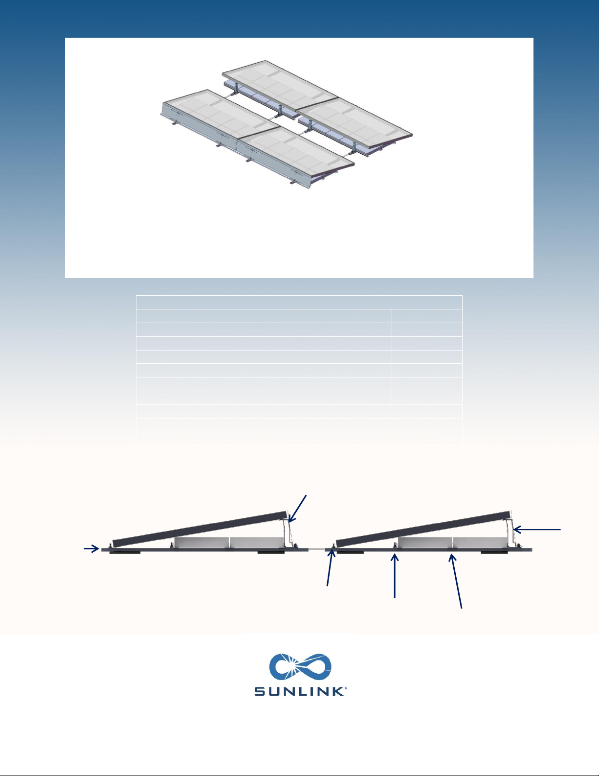
Ballast –Precision-Modular RMS is a ballasted system, meaning that its primary means of retention on the roof is the weight of the
system. The ballast is engineered to work with the environmental and structural constraints of each project, therefore the number
and location of ballast units shown on the engineering documentation needs to be strictly adhered to. Any alterations considered
need to be approved by SunLink.
Field modifications –Unauthorized field modification of SunLink components or assemblies may affect SunLink warranty coverage.
Provide marked up drawings for SunLink’s review, comment and approval prior to attempting any field modifications.
Fire Safe Roof –Precision-Modular RMS is to be mounted over a fire resistant roof covering rated for the application. Precision-
Modular RMS is not meant for sloped roofs where the slope is greater than 1/2 in perft , (2.3° or 7%.)
Fit-up –Precision-Modular RMS is a designed-fit system and is assembled using fasteners and assembly bolt sets. Matching hole
locations are engineered to ensure long-term reserve assembly strength and life cycle reliability. Since undulation and slope is
required to ensure roof drainage, SunLink incorporates features that allow the array to follow the roof contour. Some connections
are adjustable and can be modified to change the geometry. In-field changes should be documented and authorized by SunLink.
Roof life and care –The service life of any roof is contingent upon care for the roof especially during equipment installation on a
roof. Avoid concentrated loads on the roof. Never drag SunLink components into place. Instead, elevate the component and then
move it manually or with a cart. Locate it and then place it “on spot.” To ensure roofing system warranty continuation, work with
roofing system installation contractors to ensure roofing system –array compatibility.

Assembly Instructions for Precision-Modular RMS
REV 02-02-2016 Page 2
Notices and Safety Precautions
WARNING! Single-ply roofs are not damage tolerant. Avoid accumulation of metal fines that result from drilling or sawing metal
components. Metal fines embedded in the soles of shoes can damage single-ply roofs.
Fasteners –All required fasteners are furnished with Precision-Modular RMS. All fasteners are stainless steel. For any assembly,
finish initial bolted assembly to finger tight. Refer to this Installation Manual for detailed information on final fastener torque
requirements. Use of air-powered tools that do not incorporate means to limit applied torque may damage the head of fasteners
and is not recommended.
Final inspection –Visually inspect the assembled SunLink arrays. The suggested process consists of a row-by-row walk-through and
then a perimeter walk-around, after mechanical assembly, before electrical completion. Report any distortion in the assembly to
SunLink. Array substructure supports should be in full contact with the roof or the ground. Any indication of uneven distribution of
weight should be evaluated and corrected before continuing with electrical finishing.
NOTE: When installing Precision-Modular RMS, unless otherwise noted on the layout drawings, the recommended practice is to allow
for up to 4 inches of array movement on the roof. Movements can be caused by thermal effects, roof vibrations, earthquakes and
wind storms. It is also recommended to install a service loop for all electrical wiring entering or leaving the array, and for any wiring
that crosses between two unconnected structural components within the array.
GENERAL PROCEDURE NOTES
A. Precision-Modular RMS primary assembly supports 1 module in landscape orientation.
B. At the end of every work day ensure all components are securely attached
C. For all handling of components, wear gloves.
D. Be careful of pinch hazards, especially when installing panel assemblies.
E. Be careful of trip hazards. Beams, especially the Rails, present a trip hazard.
F. Careful control of small parts on the roof will ensure that shortages will not occur and will minimize the risk of damage to
the roof membrane.
For more installation guidance, please visit youtube.com/sunlink4installers.

Assembly Instructions for Precision-Modular RMS
REV 02-02-2016 Page 3
Component and Tool Quick Reference
COMPONENTS
RAIL ASSEMBLY
(Part #s 20-0001-XXX & 62-0003-001)
SOUTH CLIP
Part # 21-0001-001 (5/16”)
21-0001-002 (1/4”)
DEFLECTOR
(Part # 22-000X-001)
RAIL LINK ASSEMBLY
Part # 23-0001-001 +Carriage Bolts
SIDE LINK
Part # 23-0003-001
BALLAST BEAM
Part # 24-0001-001 (62”)
24-0001-002 (74”)
NORTH STRUT
Part # 25-0001-001
BEAM CLIP ASSEMBLY
Part # 68-0004-001 + Carriage Bolt
T-BEAM
(Only for 2-Row Ballast)
Part # 24-0002-001(62”)
24-0002-002 (74”)
FASTENERS/TORQUE (FT LBS)
*no torque/static
Part Number
Fastener Description
South Clip
Rail
North
Strut
Ballast Beam
Clip
Side Link
Connector
09-00001-01
Hex Flange Nut 1/4-20
*
09-00002-01
Hex Flange Nut 5/16-18
*
9-11
9-11
9-11
9-11
09-00122-01
Carriage Bolt 5/16-18 x 1.25
*
*
*
*
*
09-00103-01
Hex head Cap Screw - 5/16-18 x .75
9-11
09-00177-01
Hex Head Cap Screw - 1/4-20x.75
5-6
REQUIRED INSTALLATION TOOLS
Minimum two (2) saw horses or 6ft table (e.g. Stanley 11012 - 32” high, 4” long, 29” wide)
Cordless screwdriver
with torque adjustment
1/2” wrench and socket for cordless
screwdriver
7/16” wrench
(only for modules requiring ¼-20 bolts)

Assembly Instructions for Precision-Modular RMS
REV 02-02-2016 Page 4
PREP STEP –Component Preassembly
PREP STEP –JIG ASSEMBLY
One of the best features of Precision-Modular RMS is that it uses a project module and two simple locator attachments
to create a perfectly sized, foolproof project jig. By using a module as the foundation for the jig,
measurements are exact and there is no need for any measuring or aligning on the roof.
A. Borrow one project module to create the project jig and
place face-down on a table or two saw-horses.
Note: Only one jig is required, but if crew size allows,
several jigs can be created according to these steps.
B. Mount the North Rail Locator on one side of the
Module frame, using fasteners provided (Hex head bolt
and flanged nut) with the correct size for the module
mounting holes (1/4” or 5/16”). Ensure that the
registration tabs of the Rail Locators are engaged
against the inside edge of the frame before bolting to
the mounting holes.
Note: If the frame has slotted mounting holes, push all
locator fasteners to the outside of the slotted holes.
C. Mount the two South Rail Locators on the opposite side
of the Module frame, following the same procedure as
the North Rail Locators.
JIG COMPONENTS –ATTACHED TO A PROJECT MODULE TO AUTO-ALIGN AND MEASURE ALL RACKING COMPONENTS
NORTH RAIL LOCATOR
Part # 29-0013-001
SOUTH RAIL LOCATOR
Part # 29-0014-001
N
South Rail
Locator
Registration
Tabs
Registration
Tabs

Assembly Instructions for Precision-Modular RMS
REV 02-02-2016 Page 5
Appendix A –Alternative Configurations
PREP STEP –COMPONENT PREASSEMBLY
To speed installation on the roof, components can be preassembled off-the-roof or off-site.
Rail Link Assembly
A. Mount 2 carriage bolts and nuts on each Rail Link,
using the correct hole option (there are four) to
correspond to the proper row space setting.
B. See SunLink layout for row spacing and corresponding
correct hole option.
Beam Clip Assembly
A. Create Beam Clip assemblies using carriage bolts and
nuts as shown.
Rail Assembly
A. Insert two feet on each rail, positioned 1-2 inches from
one end (South) and 5-7 inches from the other end
(North).
B. On rails used with two rows of ballast add a foot 12
inches from the North foot
C. On Outrigger rails add two feet 1-2 inches from the
ends; add another two feet spaced 12 inches from the
North foot.
North end bolt
Registration tabs

Assembly Instructions for Precision-Modular RMS
REV 02-02-2016 Page 6
Step 1 –Assemble Racking Structures
Note that the Racking Structure assembly process described below can be completed off-roof or off-site
in a controlled environment at waist height.
A. Place two Rail assemblies on the Jig (as created in the
Prep Step on page 4) so that the south edge registers
against the South Rail Locator. The feet should engage
the Locators so insure that the rail is oriented correctly
(the foot position determined the orientation).
Note: For Outrigger installation, a longer Rail is used
with four Feet per Rail. See Appendix A for more details
on Outrigger installation and for racking structure for
Double Row Ballast.
B. Slide one Beam Clip assembly into the slot on each Rail
from the south end, past the Cross Beam Locator.
C. Place two Ballast Beams across the Rails, registering
them against the jig’s Cross Beam Locators.
Note: For 12x12 Ballast: the south Ballast Beam is
placed on the first notch of the North Rail Locators for
single row ballast, and against the end of the North Rail
Locator for two ballast rows. For 8x16 Ballast: the
south Ballast Beam is placed on the second notch of the
North Rail Locators.
D. Fasten the Beam Clip assembly to the South Ballast
Beam.
E. Position 2 North Struts –1 over each Rail, engaging the
north Ballast Beam.
F. Slide one Rail Link Assembly (as assembled in the Prep
Step described on page 5) into each Rail by inserting the
north end bolt into the Rail and North Strut slots.
Fasten bolt.
Note: Ensure that the Ballast Beam is registered against
the Cross Beam Locator when tightening bolt.
A
B
F
N
End of Locator
Second Notch
First Notch

Assembly Instructions for Precision–Modular RMS
REV 02-02-2016 Page 7
Step 2 –Layout Racking Structures on Roof
A. Position each Racking Structure (as created on Page 6
or in Appendix B) on the roof according to the SunLink
layout.
B. Engage Rail Links on the south end of the previous row
by sliding them into the Rail slot of the new row until
the registration tabs stop against the Rail.
Note: Additional feet may be stacked if shimming is
required on the roof.
C. When installing a new North-South column of racking
structures, ensure that adjacent columns are one
deflector length apart.
D. E/W racking can be squared by use of a wooden jig cut
to length per the column spacing on the SunLink
layout.
E. Load ballast on Ballast Beams per SunLink layout.
N
B
Foot shim on roof as required
D

Assembly Instructions for Precision-Modular RMS
REV 02-02-2016 Page 8
Step 3 –Install Modules and Deflectors
A. Use hex head cap screw and nut to attach 2 South
Clips to the south side of each PV module using the
same mounting holes as used to construct the Jig (on
page 4) to ensure proper spacing. Use 5/16”-18 or
1/4”-20 HHCS depending on module mounting hole.
dimensions and module manufacturer requirements.
Note: Ensure that the serrated flange nut is located on
the inside of the module frame. This is necessary for
proper grounding of the module.
B. Torque according to table on page 3.
Note: Ensure that the clips register against the inside
edge of the frame.
C. Center the PV module over the Rails using the South
Clip alignment tabs.
D. Lower the north side of the PV module onto the North
Struts.
E. Slide the module back to engage the hooks on the
North Struts.
F. Ensure the South Clip is engaged with the bolt that is
preassembled to the next row Rail link.
G. Torque south clip bolts (according to table)
H. Place the Deflector symmetrically over the bolts
protruding from the North Struts, engaging the large
rectangular slots on the North Strut hooks.
Note: If Wire Trays are to be used, see Appendix C
before placing deflectors.
I. Place Side Links over the Deflectors between all
adjacent modules, aligning the center hole as closely
as possible with the edge of the Deflectors.
J. Fasten with two nuts and torque according to table on
Page 3.
K. Insert two hex head bolts to fasten the middle
slots of each side link to the two deflectors being
straddled.
L. Fasten with flanged nuts. Use ¼-20 fasteners
torqued according to table.
Note: Not required when a wire tray is attached
to the side link.
N
South Clip
Alignment Tabs
North
Strut
Hook
A
C
D
E
I
H
K-L
J

Assembly Instructions for Precision-Modular RMS
REV 02-02-2016 Page 9
Appendix A –Alternative Configurations
Assemble Racking Structure for Double Row Ballast
A. Follow all instructions to assemble Racking Structure from
Step 1 on page 6, with the exception of Step C.
B. Instead of Step C, register the second Ballast Beam against
the outside edge of the North Rail Locators (12x12 Ballast).
Note: For 8x16 ballast size, the Ballast Beam registers on
the second notch of the North Rail Locators.
C. Each rail should include an extra foot, added at the
midpoint of each Rail.
D. When placing ballast (as shown on pg. 7), place a T-Beam
between the two Ballast Beams.
E. Ensure that the ends of the T-Beam are even with the
Ballast Beams.
Note: The T-Beam is not fastened to the Rails.
South Row Side Links
A. On the South row only, install an additional side link
between each module using the South Clip bolts to
attach.
B. Fasten with two additional nuts and torque according
to table.
N
T -Beam
N

Assembly Instructions for Precision-Modular RMS
REV 02-02-2016 Page 10
Appendix A –Alternative Configurations
Install Outriggers
A. Assemble outriggers as you would all other north row units
with double row Ballast. Place the South end of the rail
with standard configuration.
B. Include an extra pair of feet placed 1-2 inches from the
North edge.
Note: All outriggers have 3 total rows of ballast with each
outrigger rail fitted with 4 feet.
C. Before installing the Deflectors, place first Ballast Beam
across the Rails, positioning it against the North Strut.
D. Place the Deflector symmetrically over the bolts so that the
bottom edge of the Deflector engages on the Ballast Beam
and the large rectangular slots engage on the North Strut
hooks.
Note: If Wire Trays are to be used, see Appendix C
before placing deflectors.
E. Place second Ballast Beam across Rails, using a ballast
block to set its position.
Note: It is recommended to use a handmade jig (e.g. wood
block) to set outrigger ballast beam for lighter/easier
handling.
F. Secure Ballast Beam to Rail with Beam Clip Assembly.
G. Torque according to table.
Engage bottom edge of Deflector
on Ballast Beam.
B
A

Assembly Instructions for Precision-Modular RMS
REV 02-02-2016 Page 11
Appendix B –Grounding
The Precision-Modular RMS grounding method conforms to UL SUB 2703 and is certified by ETL for use with all photovoltaic
modules certified under UL STD 1703. The benefits of the Precision-Modular RMS Grounding include:
i. Reducing grounding lugs from 1 per PV module to 1 per continuous Precision-Modular RMS array. (continuous array
dependent on layout)
ii. Reducing installation time
iii. Reducing overall cost of system
To prevent unnecessary risk of fire, electrical shock or personal injury, all wiring and grounding must be done in accordance with
local codes, or in the absence of local codes, with the National Electrical Code, ANSI/NFPA No. 70-Latest Revision (for the US) or the
Canadian Electrical Code CSA C22.1 - Latest Revisions and local codes and ordinances. Precision Modular RMS is to be mounted over
a fire resistant roof covering rated for the application. Precision-Modular RMS is not meant for sloped roofs where the slope is
greater than 1 ½”:12” (7° or 12%).
***NOTE: GROUNDING HARDWARE NOT SUPPLIED BY SUNLINK***
Grounding the Continuous Array Using Direct Burial
Grounding Lugs
A. Identify grounding location at end of the array
B. Using the existing carriage bolt on the South
Clips, fasten the grounding lug as shown with a
5/16-18 nut.
C. Torque according to table.
D. Run solid copper equipment ground conductor
through lug binding screw and torque as
follows: #10 AWG, 20in lbs, #8 AWG, 25 in. lbs.,
#6 AWG, 35 in. lbs.
Note: Only one lug is required per continuous
array.
#
Qty/Lug
Part Name
Part Number (Pack Qty) [Or Equivalent Part]
1
1
Hex Flange Nut 5/16-18
SunLink: 09-00002-01
2
1
WEEB Lug 8.0, 1.60” x 0.71” x 0.47”
Wiley: 30020111
1
2

Assembly Instructions for Precision-Modular RMS
REV 02-02-2016 Page 12
Appendix C –Wire Management Recommendations
The following guidelines suggest how to string modules together and dress wire bundles for home runs. Stringing can be done in the
E-W or N-S direction. Wire bundles or conduit can be carried in the E-W direction under the modules or in front of the deflector.
They can also be carried in the N-S direction between modules or on the edge of the array.
Running Wires North/South –Between Rows
A. Before installing ballast and modules, place the
Wire Tray between the racking structures. Ensure
that the fronts of the mounting holes are roughly
aligned with the Deflector bolts.
Note: In locations where wire trays are being placed,
there should be at least 1” gap between modules to
allow space for the tray.
B. Before placing Deflectors, bend the edge flap to
accommodate Wire Trays.
C. Place the south end of the Wire Tray over the
Deflector flange. The north end of the tray should
remain underneath.
D. Run wires after installing the deflector.
E. Place side link over Wire Tray and fasten with
two ¼-20 x 0.75” HHCS.
Note: Side Link should be placed under the wiring.
OPTIONAL WIRE MANAGEMENT COMPONENTS
WIRE SUPPORT CLIP
(Part # 69-0001-001)
WIRE TRAY
(PART # 27-0002-001)
South end
North end
Bent flap on
Deflector
Wire Tray
Side Link

Assembly Instructions for Precision-Modular RMS
REV 02-02-2016 Page 13
Appendix C –Wire Management Recommendations
Running Wires Between Rows –String Connections
A. Lay wires along Rail and attach using zip ties as
shown (not supplied).
Running Wires Under the Module –String Connections
A. Secure wires as required using a generic clip
(not supplied).
B. Some clips can be mounted in two orientations
to support wires in either North/South or
East/West directions (not supplied).
C. Attach SunLink Wire Support Clips (Part # 69-
0001-001, included for North rows –additional
may be ordered separately) to North Strut.
D. Fasten wire bundles to each Wire Support Clip
with a zip-tie (not supplied).
Ex: Wiley clips (ACC-F90-1)

Assembly Instructions for Precision-Modular RMS
REV 02-02-2016 Page 14
Appendix D –Class A Fire Rating
Precision-Modular has been tested to the requirements for Class A fire application with Type 1 and Type 2 modules in accordance
with UL 1703 and UL 2703 for Low Slope applications.
To achieve a Class A fire rating, the following instructions must be followed:
On East/West edges of the array, each module must have at least two ballast blocks placed at the outer edge.
Note: East/West ballast arrangements are indicated per the SunLink drawing set. Please refer to these documents for
detailed placement.
On the South row of an array (for Type 2 modules only), install one Ballast Beam as shown using two Beam Clip assemblies.
Edge of
Array
Table of contents
Popular Inverter manuals by other brands

AM Solar
AM Solar Deluxe Upgrade 99-TRLSIG installation guide

POWER ON BOARD
POWER ON BOARD VEC550POB Owner's manual & warranty

WFCO
WFCO WF-5300 Series product manual

Toshiba
Toshiba G3 TOSVERT-130 instruction manual

Champion
Champion 200977 quick start guide

AIMS Power
AIMS Power PWRI300012120S instruction manual