2 INSTALLATION AND OPERATION MANUAL SOLAR MODULES INSTALLATION AND OPERATION MANUAL SOLAR MODULES 3
DISCLAIMER
Technical parameters and the design are subject to change. The data sheets and customer information valid at the point in time when the relevant
module was manufactured apply to the installation, mounting, and maintenance procedures for the respective solar modules. The installation tech-
niques, handling and use of the product are beyond company control. Therefore, SUNRISE assumes no responsibility for loss, damage or expense
resulting from improper installation, handling or misuse. SUNRISE module can be installed by many kinds of methods including, but are not limit
to bolting, clamping and inserting as follow, but if you want to use an installation method which is not covered in this manual, please inform us
before you install to make sure if our warranty will be covered or not.
With solar modules from Sunrise Energy Co.,LTD
(hereafter referred to as "SUNRISE") you can directly
transform the sun’s limitless energy into environmentally-
friendly solar electricity.
In order to ensure the maximum performance of your SUNRISE
solar modules, please read the following instructions care-
fully and observe all guidelines. Non-compliance may result
in damage and/or physical injury.
This installation and operation manual (hereafter also
referred to as the “Manual”) provides instructions for
the safe installation and operation of crystalline solar
modules.
Ä
Please read these instructions carefully before proceeding
with your installation.
ÄPlease retain these instructions for the life of the solar
modules.
Ä
Please ensure that this Manual is available to the operator
at all times.
ÄThis Manual should be given to all subsequent owners
or users of the solar modules.
Ä
All supplements received from the manufacturer should
be included.
ÄPlease observe all other applicable documents.
Ä
If your questions are not satisfactorily answered
in the manual, please contact your system supplier.
Additional information can be found on our website at
www.sunriseenergy.cn.
Intended Use
This manual is valid for Africa, Asia, Europe, Latin
America, and South America. These instructions contain
information regarding the safe handling and use of quality
crystalline solar modules from SUNRISE and for their
installation, mounting, wiring, maintenance and disposal.
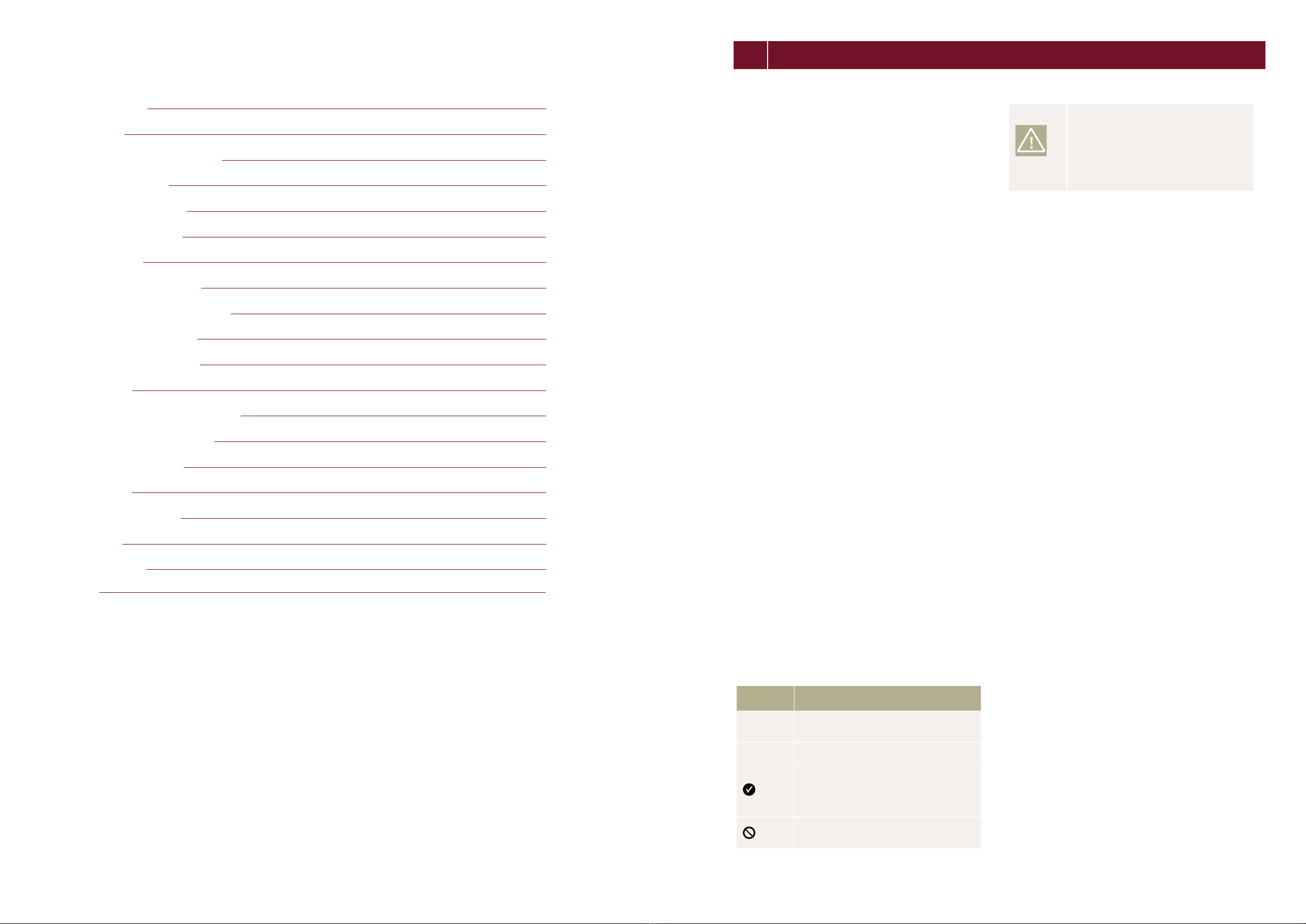
Symbols and Labels
The following symbols and labels are used throughout the
Manual for ease of use.
SYMBOL DESCRIPTION
ÄProcedure with one or more steps.
• Lists of items.
Ensure that when carrying out a pro-
cedure, you check the results of said
procedure.
Prohibited.
Beware of possible danger or damage.
Categories:
•Danger: Risk of fatal injury
•Attention: Risk of serious injury
or damage to property
•Note: Risk of damage to product
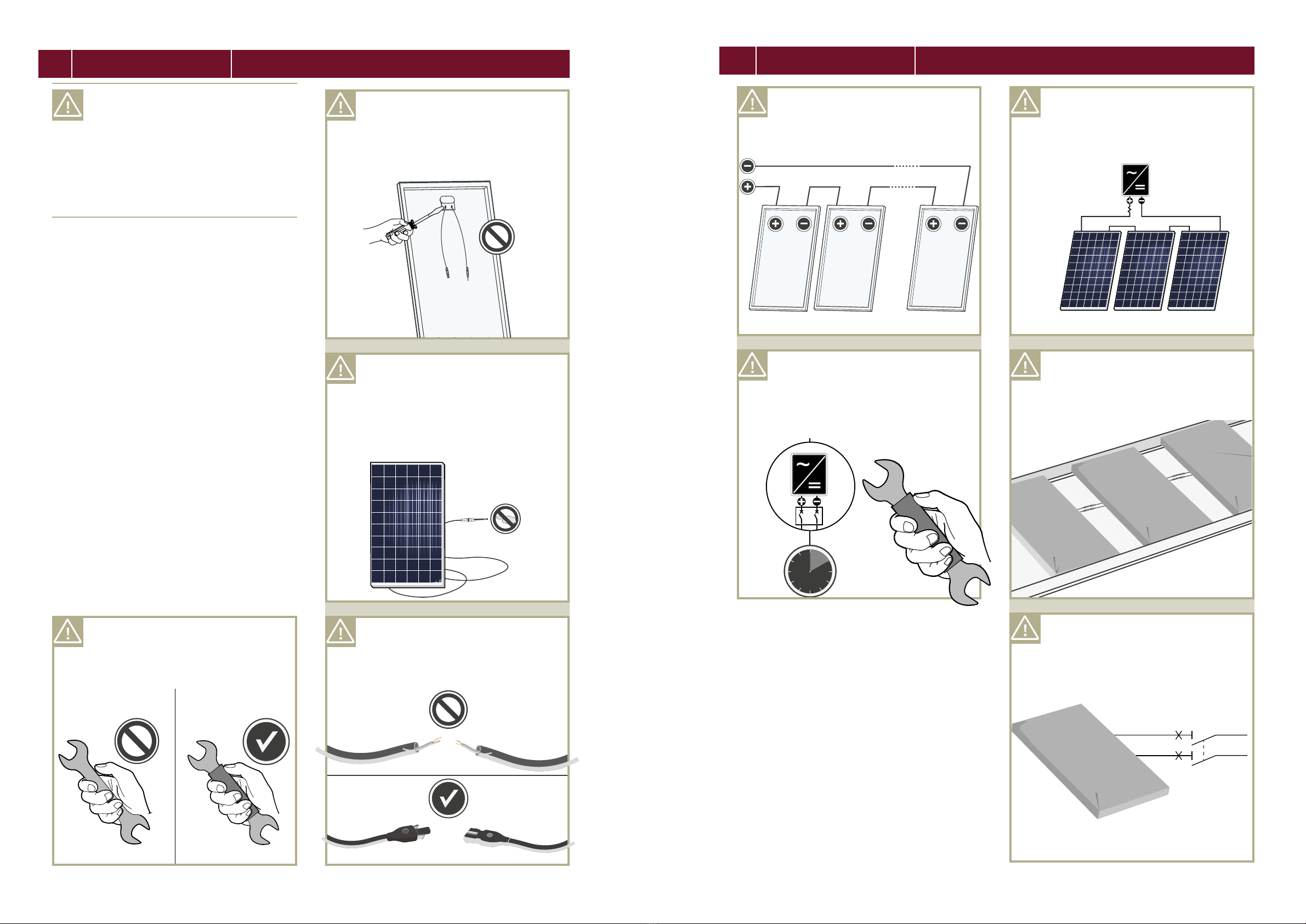
Safety Regulations
In particular the installer as well as the operator of a
module is responsible for compliance with all applicable
statutory requirements and regulations.
ÄUnless otherwise specied by any laws or regulations,
the following stipulations must be upheld at all times
during the installation, operation, and maintenance of
the solar modules:
•This manual.
•
Other applicable stipulations (such as country-specic
regulations for pressure equipment, operational safety,
hazardous goods, and environmental protection).
•
Regulations and requirements specic to the system.
•Any applicable laws and requirements, in particular
international, country specic, regional laws and
stipulations governing the planning, installation, and
operation of solar power systems and work on roofs.
•
Any valid international, national and regional regulations
governing work with direct current, especially those
applicable to the installation of electrical devices and
systems, and regulations issued by the respective
energy provider governing the parallel operation of
solar power systems.
•Any international, country specic and regional
accident-prevention regulations.
•
Other applicable stipulations provided by the relevant
national institutions regarding safety in the installation
and operation of electrical items.
Qualied & Skilled Personnel
Both, the installer and operator are responsible for
ensuring that installation (including connection to the
grid), maintenance and dismantling are carried out by
trained and qualied specialists with approved training
certicates (issued by a state or federal organization) for
the respective specialist trade.
Electrical work may only be performed by an ofcially
certied tradesperson in accordance with the stipulations
applicable in the relevant country with regard to norm and
regulations (in Germany e.g. DIN norms, VDE regulations)
and the stipulations of the local grid operator and/or
energy provider.
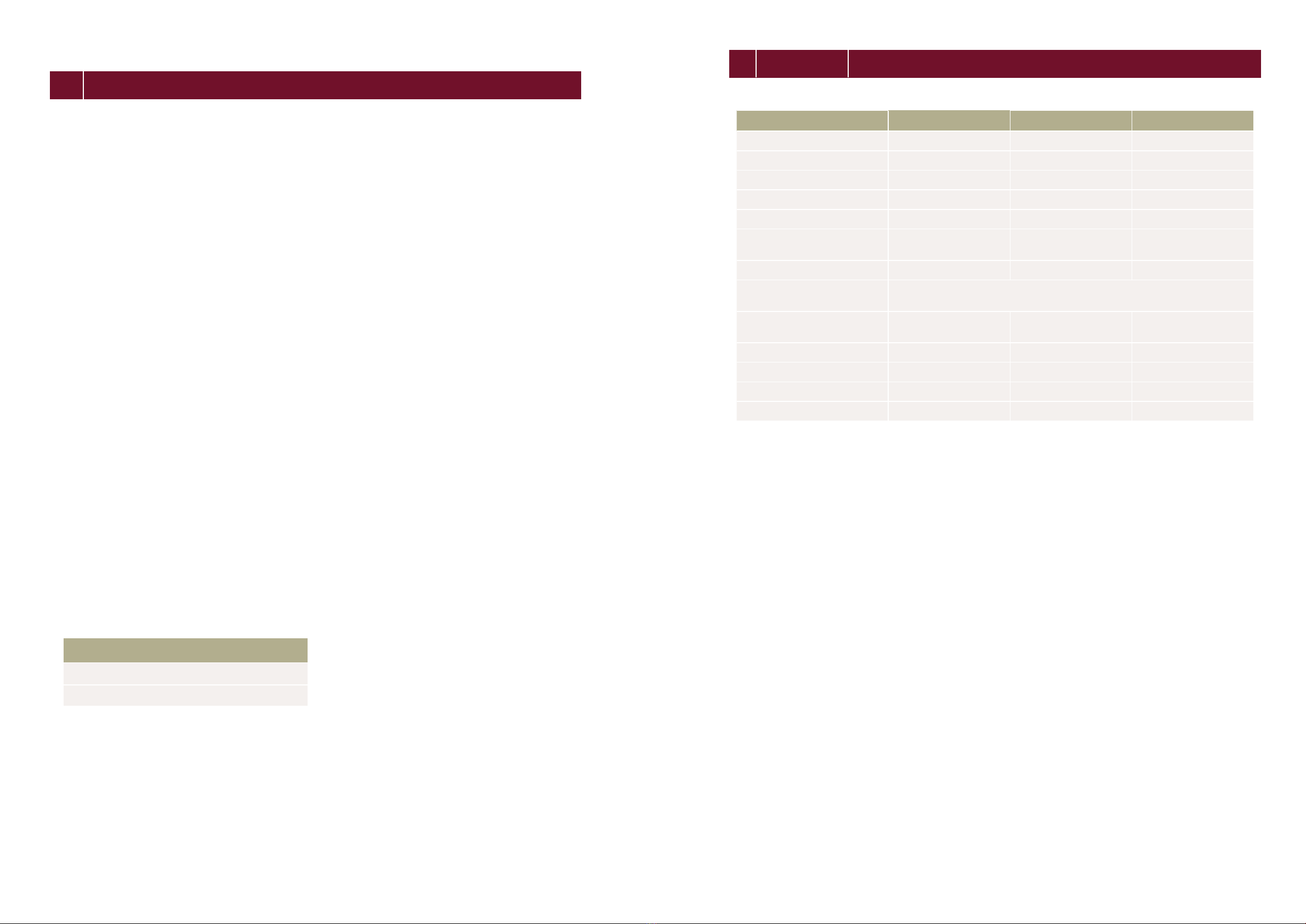
TABLE OF CONTENTS
1 INTRODUCTION 3
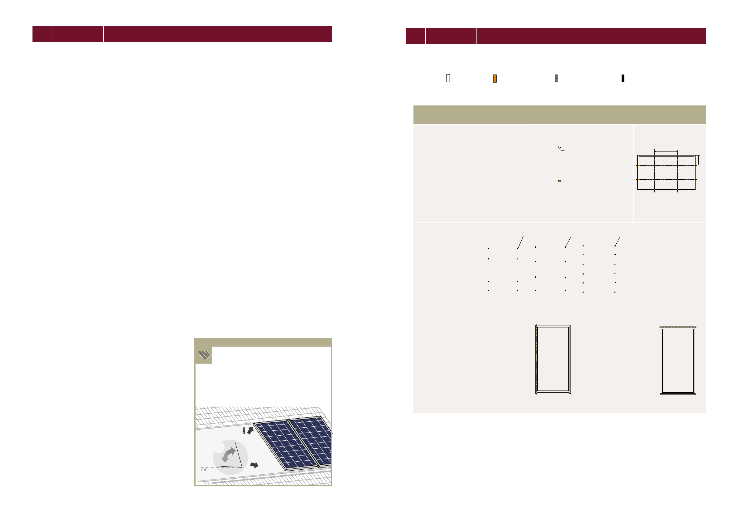
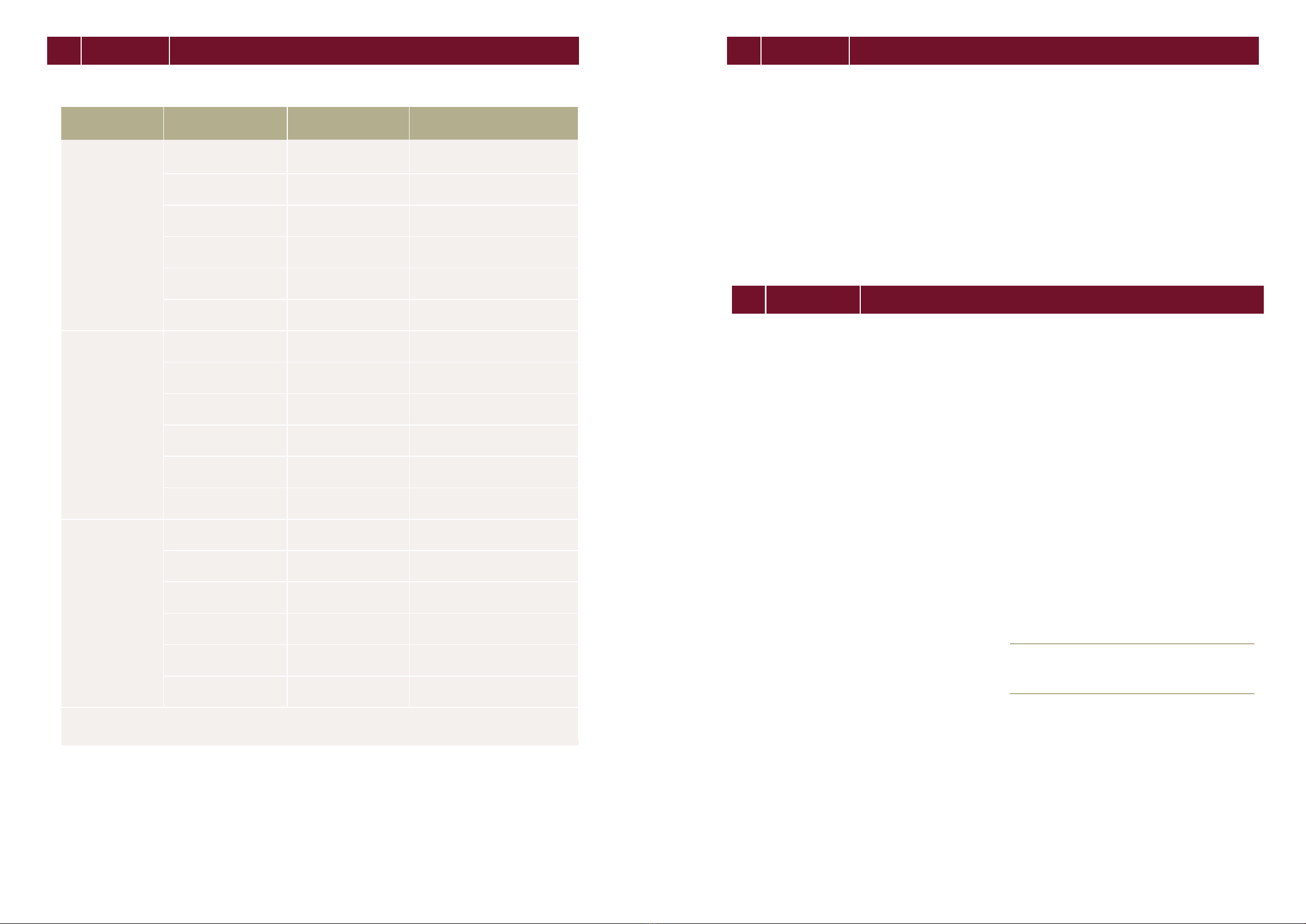
2 PLANNING 5
2.1 Technical specications 5
2.2 Requirements 6
2.3 Mounting options 7
2.4 Electrical layout 9
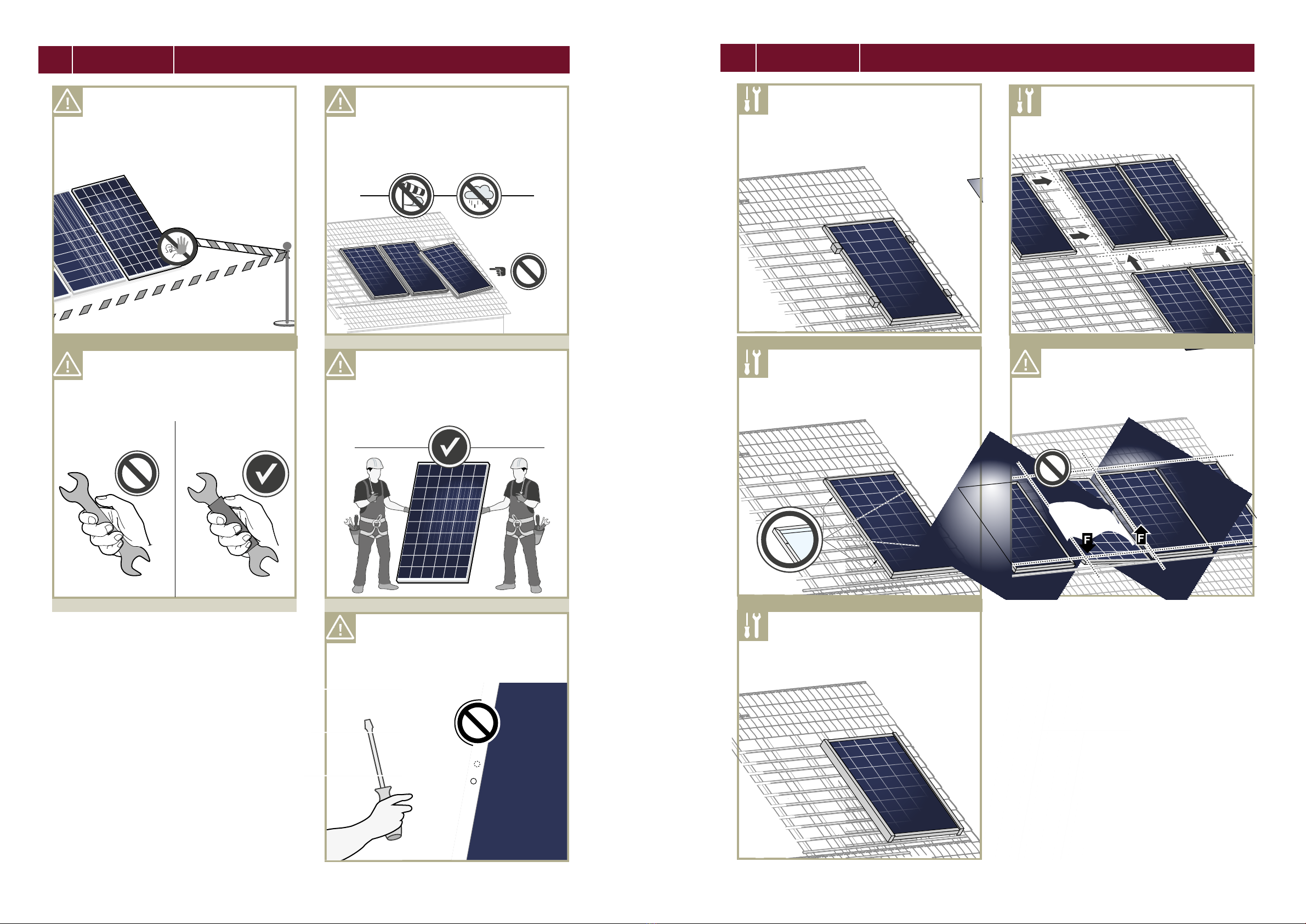
3 INSTALLATION 10
3.1 Safety and transport 10
3.2 Preparation of installation 12
3.3 Module installation 13
4 ELECTRICAL CONNECTION 14
4.1 Safety 14
4.2 Electrical installation safety 15
4.3 Connection of modules 16
4.4 After installation 17
5 GROUNDING 18
6 FAULTS AND DEFECTS 18
7 DISPOSAL 18
8 MAINTENANCE 18
1
INTRODUCTION
9NOTE 19
1 INTRODUCTION