Sunsystem P Series User manual

BUFFER TANKS
TECHNICAL PASPORT
INSTALLATION AND OPERATION MANUAL
Version 0.7
series P/PS/PSM/PBM/SPBM
up to 5000 L
EN

2
INSTALLATION and OPERATION MANUAL
INSTALLATION and OPERATION MANUALINSTALLATION and OPERATION MANUAL

3
INSTALLATION and OPERATION MANUAL
CONTENTS
1. INSTRUCTION TO INSTALLER ................................................................................ 4
1.1. Requirementstowatertankinstallaonroom. .................................................... 4
1.2. Requirementsforinstallaon................................................................................ 4
2. DESCRIPTION OF BUFFER TANK............................................................................ 4
2.1. Insulaonandoutercasing. .................................................................................. 6
2.2. Connecngofsafetyreliefvalvetobuertank......................................................6
2.3. Thermometer..........................................................................................................6
2.4.Electricheangelement........................................................................................7
2.5. Thermostat............................................................................................................10
3. TECHNICALPARAMETERSBUFFERS-Рseries .................................................. 14
4. TECHNICALPARAMETERSBUFFERS-РBMseries .............................................. 20
5. TECHNICALPARAMETERSBUFFERS-SРBMseries............................................. 26
6. TECHNICALPARAMETERSBUFFERS-РSseries .................................................. 32
7. TECHNICALPARAMETERSBUFFERS-РSMseries............................................... 35
8. SCHEMES...............................................................................................................36
9. TRANSPORT AND PACKING ................................................................................ 39
10. WARRANTY CERTIFICATE OF WATER HEATERS....................................................39
11. RECYCLING AND WASTE DISPOSAL..................................................................... 42

4
INSTALLATION and OPERATION MANUAL
INSTALLATION and OPERATION MANUALINSTALLATION and OPERATION MANUAL
1.1. Requirements to water tank
installation room
Whenchoosingaroomfortankinstallation
observethefollowingrequirements:
- to have a drainage channel. Some
maintenanceproceduresrequiredraining
of all water from the tank.
- Thermal insulation of the room. This
provides efficiency of the appliance and
preventsthewaterfromfreezing.
1.2.Requirementsforinstallaon.
•Thelengthofconnecngpipesbetween
thewatertankandconsumermustbeas
shortaspossible.
• Before connecng the boiler to the
installaon, check all screw connecons
(bolt inspecon cover ange, plug and
anode). In very rare cases - during
transportaon, loading and unloading
operaons- thescrewconneconsmay
beloosen.
• Before commissioning, check the
installaonforleaks.
•Donotexceedtheworkingpressureof
3bar.
•Ifthereisariskoffreezingofwaterin
thetank-drainthetankcompletelyorlet
thewaterheaterworksconnuously.
2. DESCRIPTION OF BUFFER TANK
Accumulatestheheatgeneratedbyboiler;
recommended for each space-heang
system. Ensures opmum operang
mode of biomass boiler, perming its
Dear Customers,
This manual contains important
informaon for the safe and correct
installaon, start-up and trouble-free
operaon and maintenance of buer
tank. Observing the instructions of this
Manualisintheinterestofthecustomer,
anditisoneoftheguaranteetermsand
conditions.
1. INSTRUCTION TO INSTALLER
The preparation, installation
and commissioning must be
performed by an authorized
installer / service.
During installation and operation, the
country specific requirements and
regulationsmustbe
observed:
• local construction regulations on
installation of water tank; weight of the
boilertocomplywith
the stability of the floor of the room
whereitwillbeinstalled.
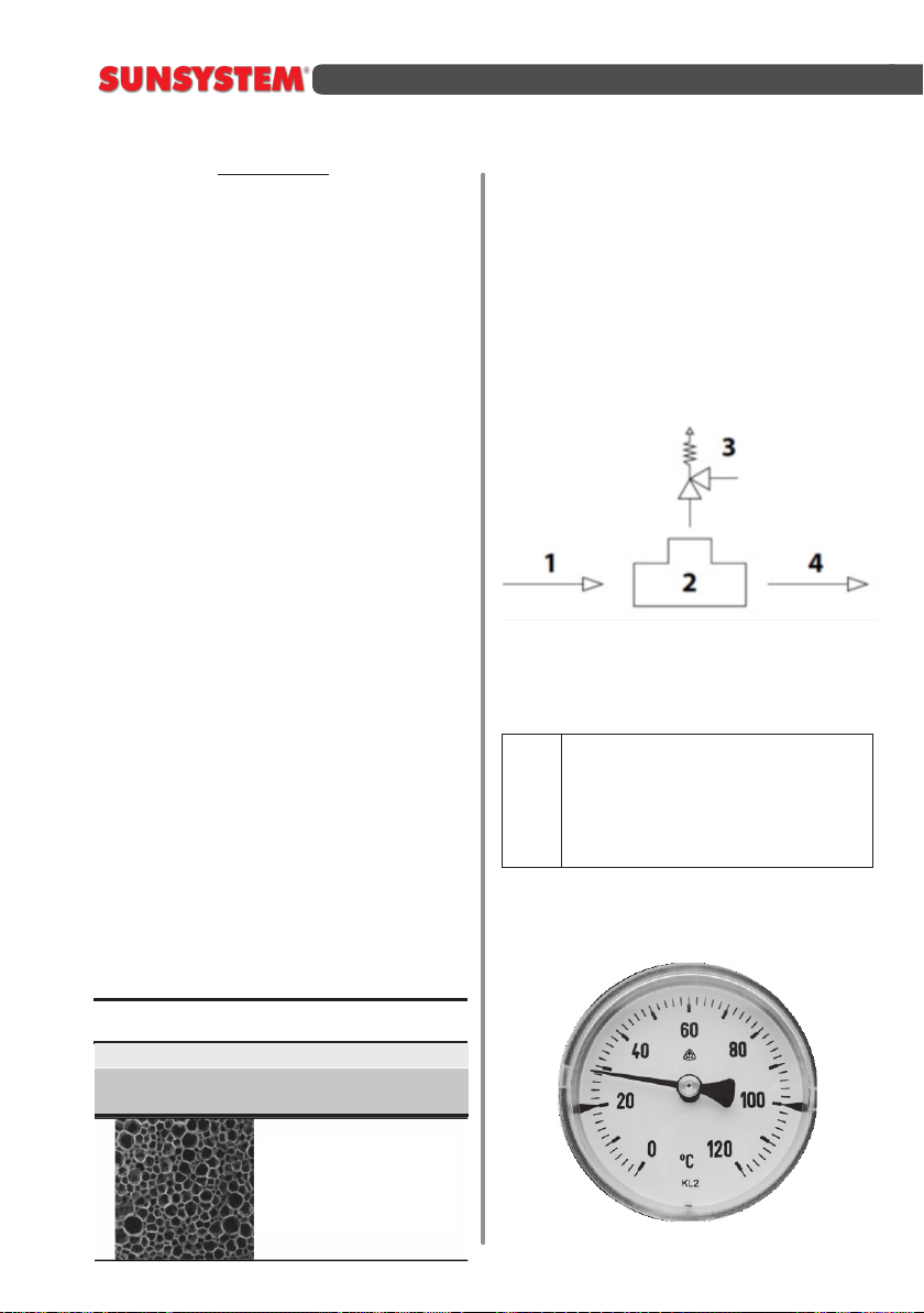
• regulations and norms concerning
the fitting of the installation with safety
devices.
• safety during installation - personal
protectiveequipment
iUse only original SUNSYSTEM
parts.

5
INSTALLATION and OPERATION MANUAL
funconingatnominalpoweroutputeven
when the heang system does not need
alltheheatenergyproducedthereby.
Producedheatisaccumulatedandstored
inside the buer tank and can be used
even when the boiler itself has cooled
down.
Рseries - Inlet/Outlet arrangement:
180 angle degrees.
Models P – without coil
Models PR – with one coil
Models PR2 - with two coils
Product features:
- Removable high eciency insulaon
withthickness 100mm andoutercasing
ofPVCwithRAL9006color.
-Mul-posionmounngoftemperature
sensor.
-Primercoatedontheoutsideofthetank.
-Heatexchangercoil/coils(PR/PR2).
-Allthreadsareinternal.
-Easyinstallaon.
Oponal kit for electric heang with
nominal power 3kW, 4.5kW, 6kW or
7.5kW.
PS series - Inlet/Outlet arrangement:
100 angle degrees.
Models PS - without coil
Models PS1 - with one coil
Models PS2 - with two coils
Product features:
- Compactdimensions.
- Highefficiencyinsulationwith
thickness50mmandoutercasingof
PVC withRAL9006color.
- Efficiencyinsulationwiththickness
20mmandfoamedpolyethylene with
RAL9006color.
(onlyformodels-80Land100L).
- Multi-positionmountingof
temperaturesensor.
- Heatexchangercoil/coils(PS1/PS2).
- Allthreadsareinternal.
- Easyinstallation.
- Optionalkitforelectricheatingwith
nominalpower3kW;
PBM series - Inlet/Outlet
arrangement: 90 angle degrees for easy
andconvenientinstallaon.
Possible installaon in the corner of
boiler room.
Models PBM - without coil
Models PBM R - with one coil
Models PBM R2 - with two coils
Product features:
Oponal removable insulaon with
thickness100mmandoutercasingofPVC
withRAL9006color.
Insulaon type available for all models:
soPU,eece.
Insulaon type available for H* models:
rigidPU.
Primercoatedontheoutsideofthetank
Upto5pcs.Rp½”sensorsleeves
Upto13pcs.Rp1”orRp1½”inlet/outlet
sleeves -connecons to heang boilers,
indirect heang of domesc hot water
(DHW)andsolarsystem
Heatexchangercoil/coils(PBMR/H*and
PBMR2/H*)
Oponal kit for electric heang with
nominal power 3kW, 4.5kW, 6kW or
7.5kW

6
INSTALLATION and OPERATION MANUAL
INSTALLATION and OPERATION MANUALINSTALLATION and OPERATION MANUAL
SPBM series -
Inlet/Outlet arrangement: 90 angle
degrees for easy and convenient
installaon.
Possibleinstallaoninthecornerofboiler
room.
Models SPBM - without coil
Models SPBM R - with one coil
Models SPBM R2 - with two coils
Product features:
- Oponal removable insulaon with
thickness 100mm and outer casing of
PVC,RAL9006color.
-Insulaontypeavailableforallmodels:
soPU,eece.
- Dividing plate (Separator). Distribuon
plate(waterstracaonunit).
-Primercoatedontheoutsideofthetank
-Upto5pcs.Rp½”sensorsleeves
Upto13pcs.Rp1”orRp1½”inlet/outlet
sleeves -connecons to heang boilers,
indirect heang of domesc hot water
(DHW)andsolarsystem
Heat exchanger coil /coils (PBM R and
PBMR2)
-Oponal kit for electric heang with
nominal power 3kW, 4.5kW, 6kW or
7.5kW
2.1.Insulaonandoutercasing
* PBM-H/ SPBM-H series – Rigid PPU
Capacity
Buertank,L Insulaontype
150, 200,
300, 500, 800, 1000, 1500,
2000, 2500, 3000, 5000
Rigid PPU 50mm
Soft PPU 100 mm
removable
The quality of the insulaon of a
water heater is a key factor for its heat
conservaon capability and energy
eciency.
All Buer tanks have a high eciency
insulaon (DIN 4753, part 8) and outer
casingwithRAL9006.
2.2. Connecting of safety relief valve
to buffer tank
1. Heating installation.
2. Tee.
3. Safety (relief) pressure valve.
4. Heat-carrier inlet.
Stop (Shut-off) valves should
never be installed between a
safety (relief) valve and the tank.
It is recommended once a year to
check the operation of the safety
valve.
2.3. Thermometer.
Amicroscopicview
ofhardpolyurethane

7
INSTALLATION and OPERATION MANUAL
2.4.Electricheangelement/opon/
Allbuffertanksareequippedwith
Outletconnection1½“forelectricheating
element:
3000W/230V;4500W/230V;
6000W/230V;7500W/400V.
The connection of the electric
heating element to the electric
power supply must be done by a
qualified electricians.
When connect the heating
element to the electric network,
make sure that it is properly
grounded.
In the table of technical parameters
is specied locaon for installaon of
electricheangelement.
Buertank
Capacity, L
Connecon Length
L, mm
Current,
W
Voltage,
V
150 ÷ 5000 1 1/2” 210 3000 230
300 ÷ 5000 1 1/2” 320 4500 230
400 ÷ 5000 1 1/2” 410 6000 230
500 ÷ 5000 1 1/2” 590 7500 230/400

8
INSTALLATION and OPERATION MANUAL
INSTALLATION and OPERATION MANUALINSTALLATION and OPERATION MANUAL
CONNECTIONS SCHEMES

9
INSTALLATION and OPERATION MANUAL

10
INSTALLATION and OPERATION MANUAL
INSTALLATION and OPERATION MANUALINSTALLATION and OPERATION MANUAL
TECHNICAL CHARACTERISTICS
Temperature range – regulation:
0°C÷90°C,limit:90°C÷110°C
Tolerance – regulation:±5k,limit-15k;-
6k(dependsonthetype)
Temperature differential – regulation:6
±2k;4±1k(dependsonthetype),limit25
±8k;15±8k(dependsonthetype)
Automatic adjustment (TLSC/A) and
manualadjustment(TLSC).
Degreeofprotection=IP 40.
Insulationclass=I.
Temperaturechangerate≤1K/min.
Maximaltemperaturepoint=80°C.
Maximaltemperatureforelectriclamp=
125°C
Accumulationtemperature=15°C ÷ 55°C.
Maximumpressureofthecartridge=10
bar.
Constanttime≤1';.
Electricconnection:
C-1 ADJ.: 10(2,5)A/250V~;
C-2 ADJ.: 6(2,5)A/250V~;
C-1 LIM.: 0,5A/250V~;
C2 LIM.: 10(2,5)A/250V~;
2.5.Thermostat/opon/.
schema 1
ThisisanadjustabledoubleTHERMOSTAT
which is designed to regulate the water
temperatureandensuressafetytolerance;
itcanbemanuallyadjusted(TLSCmodel)
orautomacallyadjusted(TLSC/Amodel).
CONFORMITY WITH STANDARDS
Thisproductisinconformitywith:
-EN60730-1andsubsequenteditions;
-EN60730-2-9
CONFORMITY WITH REGULATIONS
Thisproductcomplieswith:
-LowVoltageDirective73/23EEC
-ElectromagneticCompatibilityDirective
89/336/EC

11
INSTALLATION and OPERATION MANUAL
Terminal – circuit breaker or switch-on
contacts.
Switch-onaction–2B.
Placeofinstallation–NORMAL.
Typeofwire–M20 x 1.5.
WARNING! All installation
operations, including manual
adjustments, must be fulfilled by
a qualified specialist following all
safety conditions.
INSTALLATION AND CONNECTION
Safety instructions:
Beforeconnecting thethermostat,make
sure that THE UNIT TO BE THERMALLY
CONTROLLED (water heater, pump, etc.)
ISNOTCONNECTEDtothepowersupply
network, and is in compliance with the
instructionsinschema2.
schema 2
а)SeeSchema3and4.
schema 3
schema 4
b)Unscrew the three bolts and remove
thefrontpartofthethermostat.Unravel
the power supply wires and connect
them to the terminals of the thermostat
(Schema5)followingtheinstrucons.
schema 5

12
INSTALLATION and OPERATION MANUAL
INSTALLATION and OPERATION MANUALINSTALLATION and OPERATION MANUAL
TEMPERATURE ADJUSTMENT
A – Reset button (only for TLSC)
B – Knob for temperature adjustment
schema 8
schema 6
NOTE: See Figure 6.
To close the front part, the cartridge
opening must align with the coupling of
the adjustment knob.
CONNECTION LIMITATION
TERMINAL 2–opensthecircuitwhenthe
temperaturerises.
TERMINAL C–commoncontact.
THERMOSTAT
TERMINAL 1–opensthecircuitwhenthe
temperaturerises.
TERMINAL 2–closesthecircuitwhenthe
temperaturerises
TERMINAL C–commoncontact
schema 7

13
INSTALLATION and OPERATION MANUAL

14
INSTALLATION and OPERATION MANUAL
INSTALLATION and OPERATION MANUALINSTALLATION and OPERATION MANUAL
3.TECHNICALPARAMETERSBUFFERS-Рseries
3.1.ModelР-
without coIl
P 300 P 500 P 800 P 1000
Capacity L 300 500 800 1000
Heightwithoutinsulaon/withinsulaon H,Hi,mm 1410/1460 1610/1660 1860/1910 2040/2090
Minimalvercalclearance mm 1430 1640 1900 2075
Diameterwithoutinsulaon/withinsulaon D,mm Ø650/750 Ø650/850 Ø790/990 Ø790/990
Operangpressure/Max.buertemperature bar/0C3/95 3/95 3/95 3/95
Recommendedboilersize,connectedtobuertank kW 6-10 10-17 15-27 18-33
Weightwithoutinsulaon/withinsulaon kg,kgi 60/70 90/102 118/134 133/151
SleeveforElectricheangelement В,mm,Rp11/2”760 790 920 1130
Heatcarrier С1,mm,Rp11/2”1170 1370 1573 1742
Heatcarrier С2,mm,Rp11/2”1390 1520
Heatcarrier С3,mm,Rp11/2” 880 990
Heatcarrier С4,mm,Rp11/2”770 880 980 1060
Heatcarrier С5,mm,Rp11/2”540 620 670 730
Heatcarrier С6,mm,Rp11/2”150 150 170 170
Heatcarrier С7,mm,
Heatcarrier С8,mm,Rp11/2”660 770 820 880
Heatcarrier С9,mm,Rp11/2”260 250 310 310
Sensorsleeve А1,mm,Rp1/2” 410 410 570 580
Sensorsleeve А2,mm,Rp1/2” 1060 1120 1290 1500
Sensorsleeve А3,mm,Rp1/2” 1010 1120 1290 1450
Sensorsleeve А4,mm,Rp1/2” 420 460 465 495
Airventsleeve F,mm,Rp11/2”1410 1610 1860 2040

15
INSTALLATION and OPERATION MANUAL
P 1500 P 2000 P 2500 Р3000 P 5000
Capacity L 1500 2000 2500 3000 5000
Heightwithoutinsulaon/withinsulaon H,Hi,mm 2150/2220 2132/2182 2482/2532 2246/2296 2940/2990
Minimalvercalclearance mm 2220 2220 2542 2332 3066
Diameterwithoutinsulaon/withinsulaon D,mm Ø1000/1200 Ø1200/1400 Ø1250/1450 Ø1400/1600 Ø1600/1800
Operangpressure/Max.buertemperature bar/0C3/95 3/95 3/95 3/95 3/95
Recommendedboilersize,connectedto
buertank
kW 27-50 36-67 46-84 55-100 91-167
Weightwithoutinsulaon/withinsulaon kg,kgi 206/229 273/300 305/335 402/437 585/625
SleeveforElectricheangelement В,mm,Rp11/2”1130 1170 1170 1184 1505
Heatcarrier С1,mm,Rp11/2” 1808 1775 2126 1797 2438
Heatcarrier С2,mm,Rp11/2”1635
Heatcarrier С3,mm,Rp11/2”1305 1420 1474 2115
Heatcarrier С4,mm,Rp11/2” 1085 1170 1420 1184 1735
Heatcarrier С5,mm,Rp11/2”765 735 735 864 1155
Heatcarrier С6,mm,Rp11/2”235 230 230 344 385
Heatcarrier С7,mm, Rp1/2”/975 Rp11/2”/1170
Heatcarrier С8,mm,Rp11/2” 895 980 980 1082 1373
Heatcarrier С9,mm,Rp11/2”375 380 380 477 518
Sensorsleeve А1,mm,Rp1/2” 875 920 920 910 951
Sensorsleeve А2,mm,Rp1/2” 1500 1645 1645 1660 2001
Sensorsleeve А3,mm,Rp1/2” 1525 1625 1625 1590 2231
Sensorsleeve А4,mm,Rp1/2” 520 500 500 610 691
Airventsleeve F,mm,Rp11/2”2150 2132 2482 2246 2938

16
INSTALLATION and OPERATION MANUAL
INSTALLATION and OPERATION MANUALINSTALLATION and OPERATION MANUAL
3.2.ModelРR-
with one coil
PR 300 PR 500 PR 800 PR 1000
Capacity L 300 500 800 1000
Heightwithoutinsulaon/withinsulaon H,Hi,mm 1410/1460 1610/1660 1860/1910 2040/2090
Minimalvercalclearance mm 1430 1640 1900 2075
Diameterwithoutinsulaon/withinsulaon D,mm Ø650/750 Ø650/850 Ø790/990 Ø790/990
Operangpressure/Max.buertemperature bar/0C3/95 3/95 3/95 3/95
Operangpressure/Max.coiltemperature bar/0C16/110 16/110 16/110 16/110
Recommendedboilersize,connectedtobuertank kW 6-10 10-17 15-27 18-33
Weightwithoutinsulaon/withinsulaon kg,kgi 78/88 104/116 152/168 180/198
SleeveforElectricheangelement В,mm,Rp11/2”760 790 920 1130
Heatcarrier С1,mm,Rp11/2”1170 1370 1573 1742
Heatcarrier С2,mm,Rp11/2”1390 1520
Heatcarrier С3,mm,Rp11/2” 880 990
Heatcarrier С4,mm,Rp11/2”770 880 980 1060
Heatcarrier С5,mm,Rp11/2”540 620 670 730
Heatcarrier С6,mm,Rp11/2”150 150 170 170
Heatcarrier С7,mm,
Sensorsleeve А1,mm,Rp1/2” 410 410 570 580
Sensorsleeve А2,mm,Rp1/2” 1060 1120 1290 1500
Sensorsleeve А3,mm,Rp1/2” 1010 1120 1290 1450
Sensorsleeve А4,mm,Rp1/2” 420 460 465 495
Airventsleeve F,mm,Rp11/2”1410 1610 1860 2040
CoilcapacityS1 S1L 6.2 10.5 17.9 18.5
HeatexchangesurfaceS1 S1m21.0 1.7 2.9 3.0
Inlet/OutletLowercoilS1 S1i/S1o,mm,Rp1” 660/260 770/250 820/310 880/310

17
INSTALLATION and OPERATION MANUAL
PR 1500 PR 2000 PR 2500 PR 3000
Capacity L 1500 2000 2500 3000
Heightwithoutinsulaon/withinsulaon H,Hi,mm 2150/2220 2132/2182 2482/2532 2246/2296
Minimalvercalclearance mm 2220 2220 2542 2332
Diameterwithoutinsulaon/withinsulaon D,mm Ø1000/1200 Ø1200/1400 Ø1250/1450 Ø1400/1600
Operangpressure/Max.buertemperature bar/0C3/95 3/95 3/95 3/95
Operangpressure/Max.coiltemperature bar/0C16/110 16/110 16/110 16/110
Recommendedboilersize,connectedtobuertank kW 27-50 36-67 46-84 55-100
Weightwithoutinsulaon/withinsulaon kg,kgi 272/295 330/356 362/392 476/511
SleeveforElectricheangelement В,mm,Rp11/2”1130 1170 1170 1184
Heatcarrier С1,mm,Rp11/2” 1808 1775 2126 1797
Heatcarrier С2,mm,Rp11/2”1635
Heatcarrier С3,mm,Rp11/2”1305 1420 1474
Heatcarrier С4,mm,Rp11/2” 1085 1170 1420 1184
Heatcarrier С5,mm,Rp11/2”765 735 735 864
Heatcarrier С6,mm,Rp11/2”235 230 230 344
Heatcarrier С7,mm, Rp1/2”/975 Rp11/2”/1170
Sensorsleeve А1,mm,Rp1/2” 875 920 920 910
Sensorsleeve А2,mm,Rp1/2” 1500 1645 1645 1660
Sensorsleeve А3,mm,Rp1/2” 1525 1625 1625 1590
Sensorsleeve А4,mm,Rp1/2” 520 500 500 610
Airventsleeve F,mm,Rp11/2”2150 2132 2482 2246
CoilcapacityS1 S1L 21 24.6 24.6 29.9
HeatexchangesurfaceS1 S1m23.4 4.0 4.0 4.9
Inlet/OutletLowercoilS1 S1i/S1o,mm,Rp1” 895/375 980/380 980/380 1082/477

18
INSTALLATION and OPERATION MANUAL
INSTALLATION and OPERATION MANUALINSTALLATION and OPERATION MANUAL
3.3.МodelРR2-
with two coils
PR2 300 PR2 500 PR2 800 PR2 1000
Capacity L 300 500 800 1000
Heightwithoutinsulaon/withinsulaon H,Hi,mm 1410/1460 1610/1660 1860/1910 2040/2090
Minimalvercalclearance mm 1430 1640 1900 2075
Diameterwithoutinsulaon/withinsulaon D,mm Ø650/750 Ø650/850 Ø790/990 Ø790/990
Operangpressure/Max.buertemperature bar/0C3/95 3/95 3/95 3/95
Operangpressure/Max.coiltemperature bar/0C16/110 16/110 16/110 16/110
Recommendedboilersize,connectedtobuertank kW 6-10 10-17 15-27 18-33
Weightwithoutinsulaon/withinsulaon kg,kgi 83/93 118/130 189/205 203/221
SleeveforElectricheangelement В,mm,Rp11/2”760 790 920 1130
Heatcarrier С1,mm,Rp11/2”1170 1370 1573 1742
Heatcarrier С2,mm,Rp11/2”1390 1520
Heatcarrier С3,mm,Rp11/2” 880 990
Heatcarrier С4,mm,Rp11/2”770 880 980 1060
Heatcarrier С5,mm,Rp11/2”540 620 670 730
Heatcarrier С6,mm,Rp11/2”150 150 170 170
Sensorsleeve А1,mm,Rp1/2” 410 410 570 580
Sensorsleeve А2,mm,Rp1/2” 1060 1120 1290 1500
Sensorsleeve А3,mm,Rp1/2” 1010 1120 1290 1450
Sensorsleeve А4,mm,Rp1/2” 420 460 465 495
Airventsleeve F,mm,Rp11/2”1410 1610 1860 2040
Capacitylower/uppercoilS1/S2 S1/S2L 6.2/3.1 10.5/6.2 17.9/11.1 18.5/12.3
HeatexchangesurfaceS1/S2 S1/S2m21.0/0.5 1.7/1.0 2.9/1.8 3.0/2.0
Inlet/OutletLowercoiS1 S1i/S1o,mm,Rp1” 660/260 770/250 820/310 880/310
Inlet/OutletUppercoilS2 S2i/S2o,mm,Rp1” 1080/880 1270/990 1390/1072 1520/1172

19
INSTALLATION and OPERATION MANUAL
PR2 1500 PR2 2000 PR2 2500 PR2 3000
Capacity L 1500 2000 2500 3000
Heightwithoutinsulaon/withinsulaon H,Hi,mm 2150/2220 2132/2182 2482/2532 2246/2296
Minimalvercalclearance mm 2220 2220 2542 2332
Diameterwithoutinsulaon/withinsulaon D,mm Ø1000/1200 Ø1200/1400 Ø1250/1450 Ø1400/1600
Operangpressure/Max.buertemperature bar/0C3/95 3/95 3/95 3/95
Operangpressure/Max.coiltemperature bar/0C16/110 16/110 16/110 16/110
Recommendedboilersize,connectedtobuertank kW 27-50 36-67 46-84 55-100
Weightwithoutinsulaon/withinsulaon kg,kgi 306/329 366/393 400/430 520/555
SleeveforElectricheangelement В,mm,Rp11/2”1130 1170 1170 1184
Heatcarrier С1,mm,Rp11/2” 1808 1775 2126 1797
Heatcarrier С2,mm,Rp11/2”1305 1420 1474
Heatcarrier С3,mm,Rp11/2” 1085 1170 1420 1184
Heatcarrier С4,mm,Rp11/2”765 735 735 864
Heatcarrier С5,mm,Rp11/2”235 230 230 344
Heatcarrier С6,mm,Rp11/2” Rp1/2”/975 Rp11/2”/1170
Sensorsleeve А1,mm,Rp1/2” 875 920 920 910
Sensorsleeve А2,mm,Rp1/2” 1500 1645 1645 1660
Sensorsleeve А3,mm,Rp1/2” 1525 1625 1625 1590
Sensorsleeve А4,mm,Rp1/2” 520 500 500 610
Airventsleeve F,mm,Rp11/2”2150 2132 2482 2246
Capacitylower/uppercoilS1/S2 S1/S2L 21/14.8 24.6/14..8 24.6/14.8 29.9/17.1
HeatexchangesurfaceS1/S2 S1/S2m23.4/2.4 4.0/2.4 4.0/2.4 4.9/2.8
Inlet/OutletLowercoiS1 S1i/S1o,mm,Rp1” 895/375 980/380 980/380 1082/477
Inlet/OutletUppercoilS2 S2i/S2o,mm,Rp1” 1635/1225 1645/1285 1889/1525 1660/1310

20
INSTALLATION and OPERATION MANUAL
INSTALLATION and OPERATION MANUALINSTALLATION and OPERATION MANUAL
4.TECHNICALPARAMETERSBUFFERS-РBMseries
4.1.ModelРBM/PBMH*-
without coil
PBM
300
PBM
500
PBM/H*
800
PBM/H*
1000
Capacity L 300 500 800 1000
Heightwithoutinsulaon/withinsulaon H,Hi,mm 1410/1460 1700/1750 1838/1888 2039/2089
Minimalvercalclearance mm 1430 1727 1877 2073
Diameterwithoutinsulaon/withinsulaon D,mm Ø550/750 Ø650/850 Ø790/990 Ø790/990
Operangpressure/Max.buertemperature bar/0C3/95 3/95 3/95 3/95
Recommendedboilersize,connectedtobuertank kW 6-10 10-17 15-27 18-33
Weightwithoutinsulaon/withinsulaon kg,kgi 60/70 81/93 108/125 126/144
SleeveforElectricheangelement В,mm,Rp11/2” 860 997 1090 1260
Heatcarrier С1,mm,Rp11/2”240 239 290 290
Heatcarrier С2,mm,Rp11/2”240 239 290 290
Heatcarrier С3,mm,Rp11/2”550 643 710 775
Heatcarrier С4,mm,Rp11/2”550 643 710 775
Heatcarrier С5,mm,Rp11/2” 860 997 1090 1260
Heatcarrier С6,mm,Rp11/2” 860 997 1090 1260
Heatcarrier С7,mm,Rp11/2”1170 1451 1750 1750
Heatcarrier С8,mm,Rp11/2”1170 1451 1750 1750
Sensorsleeve А1,mm,Rp1/2” 240 239 290 290
Sensorsleeve А2,mm,Rp1/2” 550 643 710 775
Sensorsleeve А3,mm,Rp1/2” 860 997 1090 1260
Sensorsleeve А4,mm,Rp1/2” 1170 1451 1750 1750
Airventsleeve F,mm,Rp11/2”1410 1700 2039 2039
This manual suits for next models
82
Table of contents
Popular Industrial Equipment manuals by other brands

Tenco
Tenco ENOL MASTER Technical handbook

Nordco
Nordco C Installation, operation and maintenance manual

Rittal
Rittal CMC-TC Master II instruction manual

Siemens
Siemens SIRIUS 3TK2810-1BA4 Series operating instructions

Graco
Graco Gusmer Reactor H-25 Operation

KMT
KMT STREAMLINE SL-V SRP 100 Operation and maintenance manual