3
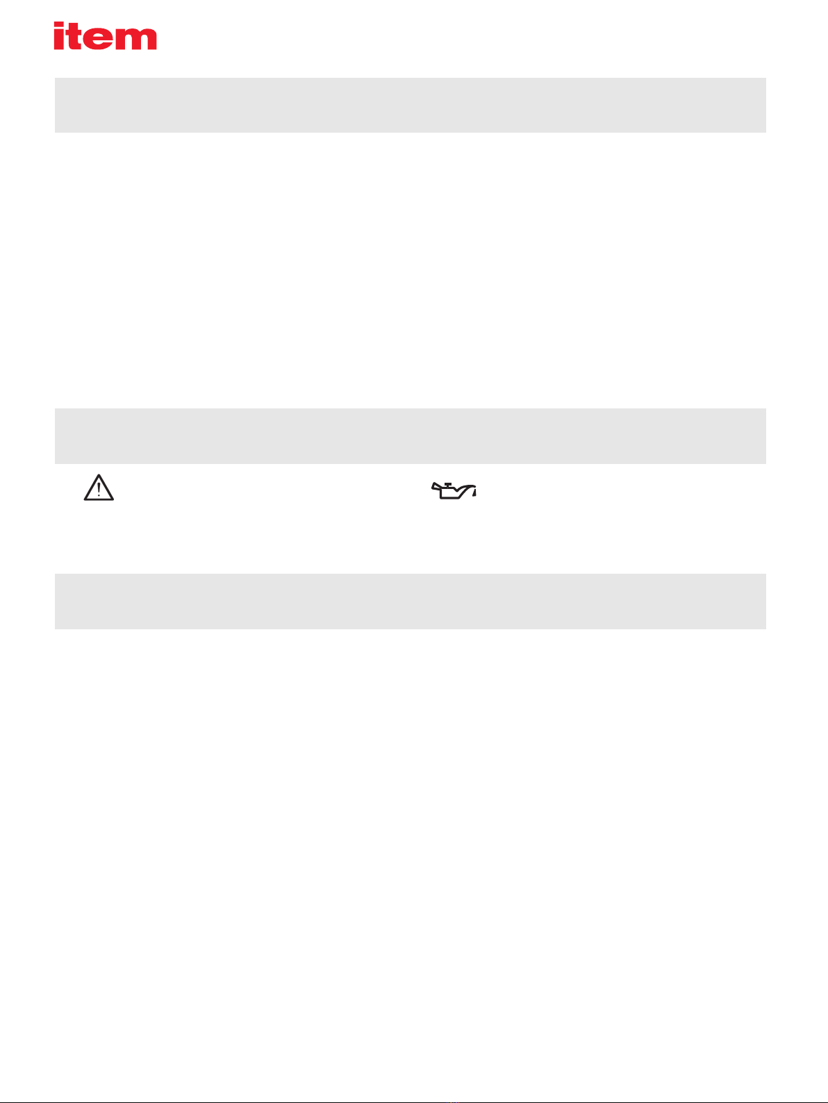
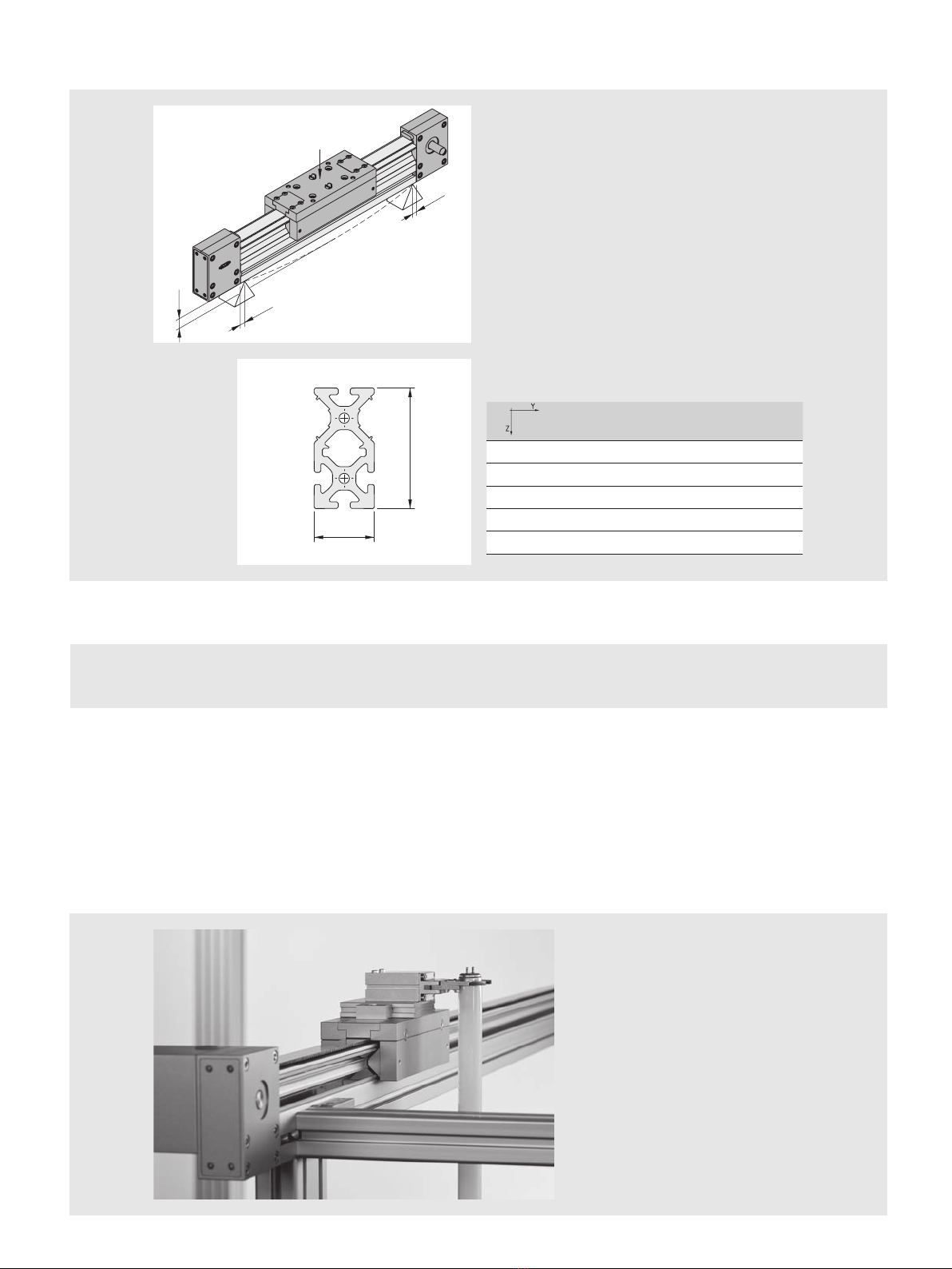
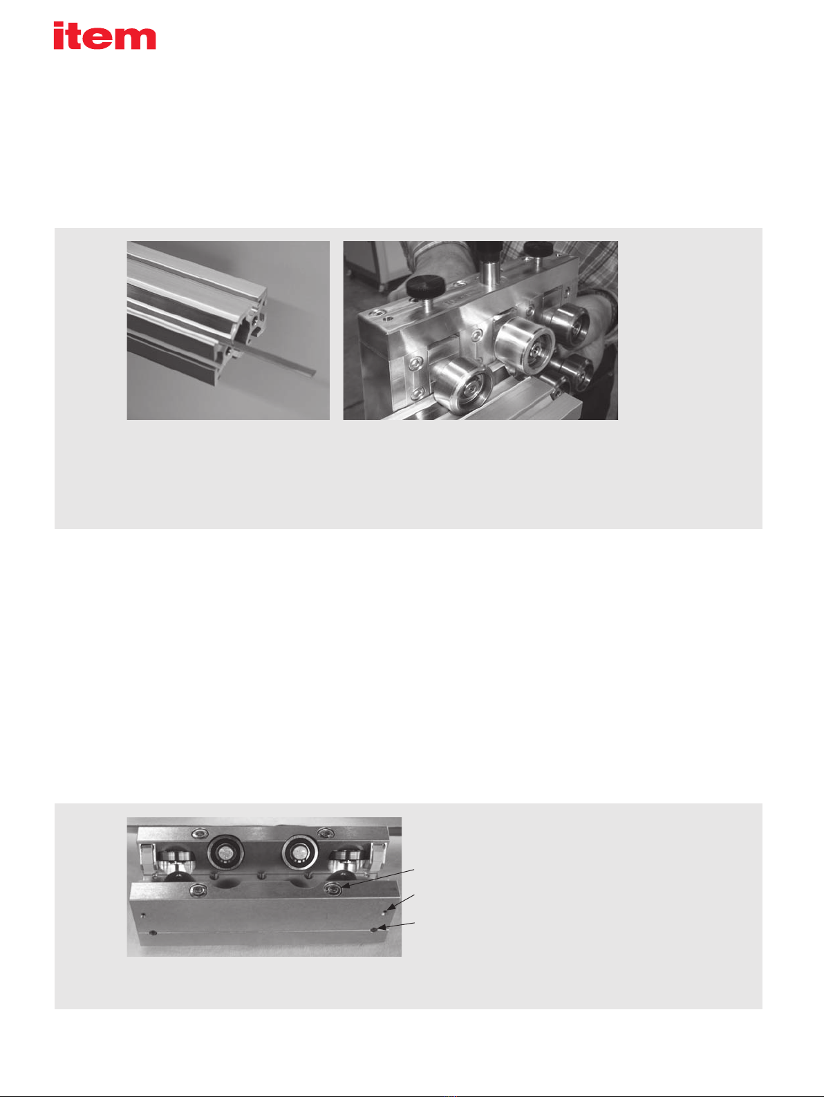
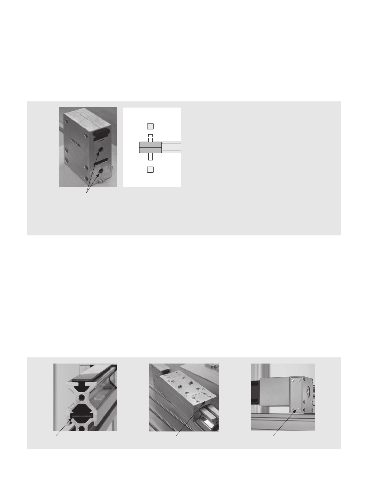
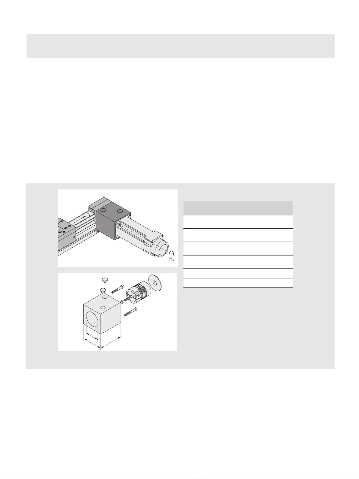
Linear Unit KRF 8 80x40 ZR
Correct use
Improper use
Linear Unit KRF 8 80x40 ZR is a partly completed machine as defined in the
Machinery Directive (2006/42/EC). Linear Unit KRF 8 80x40 ZR must only be
used in accordance with the technical data and safety requirements set out in
this document. Internal company requirements and the regulations that apply
in the country where the product is being used must be observed. You must
not make any design modifications to Linear Unit KRF 8 80x40 ZR yourself. We
will assume no liability for any resulting damage or injury. You may only install,
operate and maintain Linear Unit KRF 8 80x40 ZR if:
Linear Unit KRF 8 80x40 ZR has been integrated properly and safely into the
completed machine,
You have carefully read and understood the installation guide,
You are appropriately qualified,
You are authorised to do so by your company,
You are using only original equipment from the manufacturer.
Unsafe or inappropriate use of Linear Unit KRF 8 80x40 ZR runs a risk of serious
injury through crushing and cuts.
Improper use is defined as any use of the product for purposes other than those
authorised in the installation guide and under the definition of correct use. We
will assume no liability for any resulting damage or injury.
Linear Unit KRF 8 80x40 ZR, as described here, corresponds to the state of
the art and takes into account the general principles of safety applicable at the
time this installation guide was published. Nevertheless, failure to observe the
safety instructions and warning notices in this installation guide may result in
personal injury and damage to property.
We will assume no liability for any resulting damage or injury. We reserve the
right to make technical changes that represent technical advances. Keep these
installation notes in a place where they can be easily accessed by all users.
Observe the directions contained in the main user guide for the completed
machine.
The general safety information applies to the entire lifecycle of the partly
completed machine.
1. During transportation
Observe the handling instructions on the packaging. Until it is installed, the
product must be stored in its original packaging, protected from moisture and
damage. Ensure that moving parts are secured when in transit and cannot
cause any damage.
2. During installation
Always deactivate the power to the relevant system part and ensure it is not live
before installing the product and/or plugging it in or unplugging it. Ensure the
system cannot be switched back on. Lay cables and lines in such a way that
they cannot be damaged and do not represent a trip hazard. Avoid areas that
pose slip, trip and fall hazards.
3. During start-up
Allow the product to acclimatise for a few hours before starting it up. Ensure
that the partly completed machine is securely and safely integrated into the
completed machine. Only start up a product that has been installed in full.
4. During operation
Ensure that only persons who have been authorised by the operator have ac-
cess to the immediate operating environment of the system. This also applies
when the system is not in operation. It must not be possible to actuate moving
parts unintentionally. During emergencies, malfunctions or other irregularities,
deactivate the system and ensure that it cannot be switched back on. Prevent
the possibility of persons becoming trapped in the system’s hazard zone.
5. During cleaning
Close all openings with suitable protective equipment to ensure that cleaning
agents cannot penetrate the system. Do not use aggressive cleaning sub-
stances. Do not use a high-pressure cleaner when cleaning the system.
6. During maintenance and servicing work
Carry out the prescribed maintenance work at the intervals stipulated in the
user guide. Ensure that no line links, connections or components are removed
while the system is live and under pressure. Ensure the system cannot be
switched back on.
7. During disposal
Dispose of the product in accordance with the national and international regula-
tions that apply in your country.