EVAPCO Mr. GoodTower EAW-FD Series Manual

for
LIFE
Operation and
Maintenance Instructions
For eco-Air Dry, Adiabatic and Spray
Fluid Coolers, Condensers & CO2 Gas Coolers
International Institute of
Ammonia Refrigeration
www.iiar.org
Member of

2
DRY, ADIABATIC AND SPRAY FLUID COOLERS, CONDENSERS & CO2GAS COOLERS
3 Introduction
3 Safety Precautions
4 Terminology
4 Receiving
4 Initial Storage and/or Idle Period Recommendations
5 Initial and Seasonal Start-Up and Shut-Down
5 General
5 Initial and Seasonal Start-Up
6 Seasonal Shut-Down
6 Dry, Adiabatic or Spray Fluid Coolers
6 Dry or Adiabatic CO2 Gas Coolers and Dry,
Adiabatic or Spray Condensers
6 Basic eco-Air Series Sequence of Operation
7 Maintenance Instructions
7 Finned Coil Cleaning
7 Cleaning Hydraulically
7 Cleaning with Compressed Air
7 Cleaning with Brushes
7 Cleaning Fans
8 Adiabatic Pad Pre-Cooling System – If Equipped
9 Operation (Adiabatic Pad Pre-Cooling System)
9 Maintenance (Adiabatic Pad Pre-Cooling System)
8 Spray Pre-Cooling System – If Equipped
9 Operation (Spray Pre-Cooling System)
9 Maintenance (Spray Pre-Cooling System)
10 Inlet Water (Adiabatic Pad & Spray Pre-Cooling Systems)
11 Water Quality Guidelines (Adiabatic Pad & Spray Pre-Cooling Systems)
12 Maintenance Checklist
13 Fan System
13 Fan Belt Adjustment - Double Stack Product Line Only
14 Variable Frequency Drives
14 Sequence of Operation for Multi-Fan Units with a VFD During Peak Load
14 Variable Frequency Drive Lockout Notification
15 Cold Weather Operation
15 Unit Layout
15 Freeze Protection
16 Troubleshooting
16 Replacement Parts
17 Replacement Part Drawings
17 eco-Air Flat Coil Configuration with NEMA Fan Motors
17 eco-Air Flat Coil Configuration with EC Fan Motors
18 eco-Air V-Coil Configuration with NEMA Fan Motors
18 eco-Air V-Coil Configuration with EC Fan Motors
19 eco-Air Adiabatic Pad Pre-Cooling System Components
19 eco-Air Spray Pre-Cooling System Components
20 eco-Air Double Stack Adiabatic Cooler with EC Motors
20 eco-Air Double Stack Adiabatic Cooler with NEMA Motors
21 Notes
Table of Contents
3
DRY, ADIABATIC AND SPRAY FLUID COOLERS, CONDENSERS & CO2GAS COOLERS
Introduction
Congratulations on the purchase of your EVAPCO air cooled unit. EVAPCO equipment is constructed of the highest quality materials and
designed to provide years of reliable service when properly maintained.
Thoroughly clean road salt, dirt and debris from unit immediately aer delivery. Residue le on product surfaces can cause damage that is
not covered by any warranty. All new cooling equipment and associated piping should be pre-cleaned and flushed to remove grease, oil,
dirt, debris and other suspended solids prior to operation. Any pre-cleaning chemistry should be compatible with the cooling equipment’s
materials of construction. Alkaline formulations should be avoided for systems which include galvanized materials of construction.
Closed hydronic systems connected to a dry fluid cooler should be pre-cleaned and flushed to remove debris, grease, flash rust, oil, and
other suspended solids prior to operation. EVAPCO recommends the use of inhibitor chemistry or inhibited glycol to minimize corrosion
and scale during normal operation.
Air cooled equipment is oen remotely located and periodic maintenance checks are oen overlooked. It is important to establish a
regular maintenance program and be sure that the program is followed. This bulletin should be used as a guide to establish a program. A
clean and properly serviced unit will provide a long service life and operate at peak efficiency.
This bulletin includes recommended maintenance and maintenance intervals for unit start up, unit operation and unit shutdown. Please
note that the maintenance intervals are minimums. Maintenance should be performed more oen when operating conditions necessitate.
Become familiar with your air cooled equipment. Refer to the isometric drawings located on pages 17-20 for information on the arrange-
ment of components in your equipment.
If you should require any additional information about the installation, operation or maintenance of this equipment, contact your local
EVAPCO representative. You may also visit www.evapco.com or www.mrgoodtower.com for more information.
Safety Precautions
Qualified personnel should use proper care, procedures and tools when operating, maintaining or repairing this equipment in order to
prevent personal injury and/or property damage. The warnings listed below are to be used as guidelines only.
Never operate this equipment without fan screens and access panels properly secured and in place.
Each coil in this unit ships from the factory with a nitrogen charge on the coils. Verify that the nitrogen charge is
still applied before installing unit. Release pressure in each coil before installing heat transfer fluid piping.
An optional factory provided disconnect switch may be located on the unit for each fan motor associated with this
equipment. Before performing any type of service or inspection of the unit make certain that all power has been
disconnected and locked in the “OFF” position.
The top horizontal surface of any unit is not intended to be used as a working platform. No routine service work is
required from this area.
Closed hydronic systems connected to either a closed circuit cooler or dry cooler should be pre-cleaned and
flushed to remove debris, grease, flash rust, oil, and other suspended solids prior to operation. EVAPCO recom-
mends the use of inhibitor chemistry or inhibited glycol to minimize corrosion and scale during normal operation
EVAPCO requires that all external piping and fittings be externally supported, the supplied connections are not
designed to support external piping or fitting weights. Additional weight to the connections or coil in any way
could cause damage to the unit not covered under warranty.
4
DRY, ADIABATIC AND SPRAY FLUID COOLERS, CONDENSERS & CO2GAS COOLERS
Terminology
Throughout this manual, the terms “Flat Coil,” “V-Coil,” and “Double Stack” are used. Below is a list of EVAPCO eco-Air product offerings
and associated terminology.
eco-Air Series equipment includes the following product models:
<Dry Products
• EAW-FD/EAFWD: Flat Coil Dry Fluid Cooler
• EAW-VD/EAVWD: V-Coil Dry Fluid Cooler
• EAW-DD/EADWD: Double Stack Dry Fluid Cooler
• EAFCD: Flat Coil Dry Condenser
• EAVCD: V-Coil Dry Condenser
• EAVGD: V-Coil Dry CO2Gas Cooler
Receiving
Carefully inspect all units upon arrival to assure that no damage has occurred during shipment. This includes searching for dirt and debris
caused by shipping, as well as inspecting all components and accessories for physical damage. If any units have been damaged during
transit, immediately notify the carrier and file a claim with that carrier.
The coils on all EVAPCO eco-Air Series coolers and condensers are shipped from the factory with a low-pressure nitrogen charge.
Maintain the nitrogen charge until connecting the unit to the system piping.
Each coil is shipped with a pressure gauge to verify the nitrogen charge in the coil. A coil without the factory nitrogen charge may indicate
damage occurred during shipment. In this case, coil(s) should be pressure tested with dry nitrogen gas to assure that it is leak free prior to
installation. Please notify your EVAPCO representative before installing any unit that has lost the factory nitrogen charge during shipment.
Once the nitrogen charge is verified, release the nitrogen charge by opening the valve located on the outlet coil connection.
<Dry Products with Air Pre-Cooling Systems
•EAW-VA/EAVWA: V-Coil Adiabatic Fluid Cooler
• EAW-VS/EAVWS: V-Coil Spray Fluid Cooler
• EAW-DA/EADWA: Double Stack Adiabatic Fluid Cooler
• EAVCA: V-Coil Adiabatic Condenser
• EAVCS: V-Coil Spray Condenser
• EAVGA: V-Coil Adiabatic CO2Gas Cooler
Initial Storage and/or Idle Period Recommendations
If the unit will remain inactive for an extended period of time prior to installation it is recommended that the following be performed in
addition to all component manufacturers recommended maintenance instructions.
• The fans must be turned by hand at least once every three months. This can be accomplished by tagging and locking out the unit’s
disconnect, grasping the fan assembly and rotating it several turns.
• If unit remains inactive longer than one month, insulation test motor windings semi-annually.
• See motor manufacturer maintenance and long term storage instructions for more detailed instructions.
• Thoroughly clean road salt, dirt and debris from unit immediately prior to storage or operation. Residue le on product surfaces
can cause damage that is not covered by any warranty.
5
DRY, ADIABATIC AND SPRAY FLUID COOLERS, CONDENSERS & CO2GAS COOLERS
Initial and Seasonal Start-Up and Shut-Down
General
1. Verify that the overall installation reflects the requirements of the installation guidelines found in the EVAPCO Equipment Layout
Manual available at www.evapco.com.
2. Verify all safety interlocks work properly.
3. Examine wiring for loose connections or other obvious damage.
4. For units supplied with an EVAPCO control system, refer to The Controller User’s Manual for for motor and controls startup. For
units not supplied with controls see motor manufacturer’s and controls manufacturer’s start up recommendations.
5. If the unit is going to remain inactive for an extended period of time, follow all fan motor guidlines for long term storage. Properly
ventilated plastic sheets or tarps can be used to protect a unit during storage. See your local EVAPCO representative for additional
information on unit storage.
BEFORE BEGINNING ANY MAINTENANCE, BE CERTAIN THAT THE POWER IS TURNED OFF AND THE UNIT IS
PROPERLY LOCKED AND TAGGED OUT!
Initial and Seasonal Start-Up
1. Clean and remove any debris, such as leaves and dirt from the coil face, adiabatic pads (if equipped), and fan screens. Flush the
adiabatic pads to remove any sediment or dirt.
2. If equipped, the factory set flow setter devices on the adiabatic system piping may need to be adjusted to maintain equal
distribution of water flow on both sides of the unit.
3. Fins can be brushed clean with a so bristle brush or pressurized water, not aimed at an angle, but directly onto the fins to clean
accumulated deposits. A fin comb or needle nose pliers can be used to straighten any fins that have become bent. Fins that had
been damaged and straightened with a fin comb may not look like new but will function normally if air spaces remain open.
4. Turn the fan(s) by hand to ensure it turns freely without obstructions.
5. Visually inspect the fan blades. Blade clearance should be approximately 1/4” from tip of blade to the fan cowl.
6. For fluid coolers only, fill the heat exchanger coil with the specified heat transfer fluid and purge air from the system before
pressurizing, using factory supplied coil vents.
NOTE: Dry fluid coolers should only be used on sealed, pressurized systems. Continual aeration of the heat transfer fluid in an open
system can cause corrosion inside the tubes of the cooler leading to premature failure.
Aer the unit has been energized, check the following:
1. Verify fans are rotating in proper direction based on arrow sticker affixed to fan housing.
2. Measure voltage and current on all three power leads of fan motors. The current should not exceed the motor nameplate full load
amp rating.
3. Start the EVAPCO air pre-cooling system if equipped. For adiabatic units, check for proper pad wetting. For spray units, check to
ensure all nozzles are free from debris and have a uniform spray pattern. If the adiabatic pad or spray pre-cooling system is not
operating correctly, consult the troubleshooting guide in this manual.

6
DRY, ADIABATIC AND SPRAY FLUID COOLERS, CONDENSERS & CO2GAS COOLERS
Seasonal Shut-Down
The below steps should be taken when the equipment is shut down for prolonged periods.
DRY, ADIABATIC OR SPRAY FLUID COOLERS
1. Ensure the process is shut down and the system temperature has reached safe shut down condition.
2. If unit is equipped with an adiabatic pad or spray pre-cooling system ensure that all valves are open and system is completely drained.
3. Switch off the fans and power to the unit.
4. Close the isolating valves by others, if equipped.
5. If the cooler will be subjected to sub-zero temperatures and is not filled with a suitable antifreeze, open the air vent and drain
connection(s) and drain the heat transfer fluid. Applying a positive pressure to the air vent connection(s) will help ensure that there is no
heat transfer fluid retention, which could lead to frost damage.
DRY OR ADIABATIC CO2GAS COOLERS AND DRY, ADIABATIC OR SPRAY CONDENSERS
1. Ensure that the refrigeration load is removed.
2. If unit is equipped with an adiabatic pad or spray pre-cooling system ensure that all valves are open and system is completely drained.
3. Switch off the fans and power to the product.
Basic eco-Air Series Sequence of Operation
NOTE: For units with an EVAPCO control system, refer to The Controller User’s Manual for detailed sequence of operation.
System Off / No Load
The unit’s fans are off. Adiabatic pad or spray pre-cooling systems should be off, if equipped.
System/Condensing Temperature Rises
The fans turn on. For a variable speed controller, the fans are turned on to minimum speed, all fans maintaining the same speed. If the
system temperature continues to rise, then the fan speed is increased as required, up to full speed.
If temperatures continue to rise and an adiabatic pad or spray pre-cooling system is equipped, then the water solenoid valve should open
and completely wet adiabatic pads, or spray water from nozzles. Fan speeds are increased and decreased as needed aer adiabatic pad or
spray pre-cooling system is initiated.
NOTE: If the adiabatic or spray unit is equipped with the two-stage operation accessory, two solenoid valves are provided, and the
pre-cooling systems are actuated in two stages to reduce overall water consumption.
System/Condensing Temperature Stabilizes
Control the leaving fluid temperature (fluid and CO2gas coolers) or condensing pressure (condensers) by modulating the fan speeds with
equipped controls system.
System/Condensing Temperature Drops
Decrease the fan speed, as required. If equipped, shut off adiabatic pad or spray pre-cooling system and continue to modulate fan speed.
System Off / No Load
The system fans turns off. The adiabatic pad or spray pre-cooling system should not be used as a means of capacity control, and should
not be cycled frequently. Excessive cycling can lead to scale build-up on the pads or coils (in case of spray).
NOTE: Minimum control point for process fluid should never be lower than 6º F above process fluid freezing temperature.
7
DRY, ADIABATIC AND SPRAY FLUID COOLERS, CONDENSERS & CO2GAS COOLERS
Maintenance Instructions
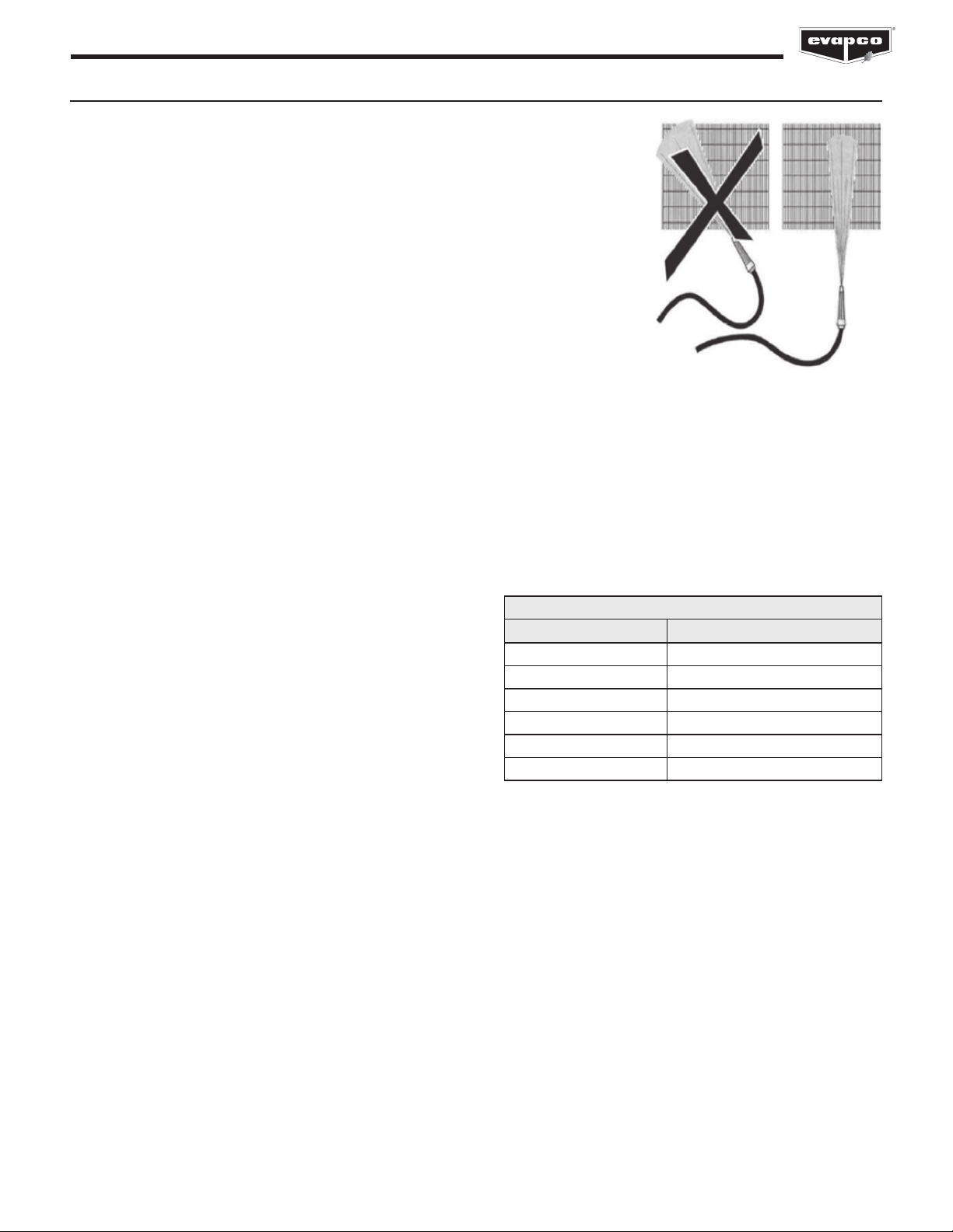
Finned Coil Cleaning
It is essential to understand that fouled or dirty fins reduce heat transfer.
1. Aer operation for a month, check for fouling of the fins. Inspect with a light between the
fins to observe the accumulations of dirt and dust.
2. Dry dust can normally be removed by compressed air, a so brush, or by a suitable
industrial vacuum cleaner. Sweep along the fins and under no circumstances across the
fins.
3. Moist or sticky blemishes or grease should be removed by means of hot water or steam jet
cleaning appliances (against the air direction).
4. Keep the jet of the cleaning appliance at an angle of no more than 15° from vertical
position, to avoid bending the fin edges.
CLEANING HYDRAULICALLY
When cleaning the coil hydraulically, EVAPCO recommends using water only. If cleaning products are used ensure that they are
compatible with the unit materials of construction. When cleaning with water under pressure, use a power washing device designed for a
maximum of 600 psig or less.
Always clean in the vertical direction. Never across the fins, as this will damage the fins. And always from the top down to avoid the water
spray entering the fans (this can short circuit the fan motors).
For oily or otherwise difficult to remove dirt, it is possible to add a chemical cleaning agent to the water used in the power washer. Ensure
that the cleaning agent is compatible with the materials used in the unit and that it is an environmentally friendly agent.
List of recommended cleaning solutions are shown in Table 1.
Figure 1 – Always Clean Fins in
Vertical Direction
STAINLESS STEEL/ALUMINUM COILS
Trade Name Manufacturer
CL-122 NALCO
CL-127 NALCO
LMC-44 LW Chemical
SoilSolv DuChem
FS Process Cleaner Zep
Formula 940 Zep
Table 1 – Acceptable Cleaning Solutions
CLEANING WITH COMPRESSED AIR
When cleaning with compressed air, use a compressor designed for a
maximum of 1,000 psig or less. For the purpose of removing dirt and
debris, please ensure that the air stream is COMPLETELY VERTICAL to
the fins as the compressed air stream can damage the fins.
CLEANING WITH BRUSHES
Dry dust and some dirt can be removed with brushes, possibly in
conjunction with compressed air or an industrial vacuum cleaner.
However, ensure that so brushes are used and when possible all cleaning should be
from the top down. ALWAYS brush along the fins. NEVER across the fins, as this will
damage the fins.
Cleaning Fans
ALWAYS ensure that the power to fans has been locked and tagged out prior to cleaning and ensure that the fans cannot be accidentally
started during maintenance.
It is recommended to clean the fans either by means of brushes or with compressed air. When cleaning with compressed air, use a
compressor designed for a maximum discharge air pressure of 125 psig or less.
8
DRY, ADIABATIC AND SPRAY FLUID COOLERS, CONDENSERS & CO2GAS COOLERS
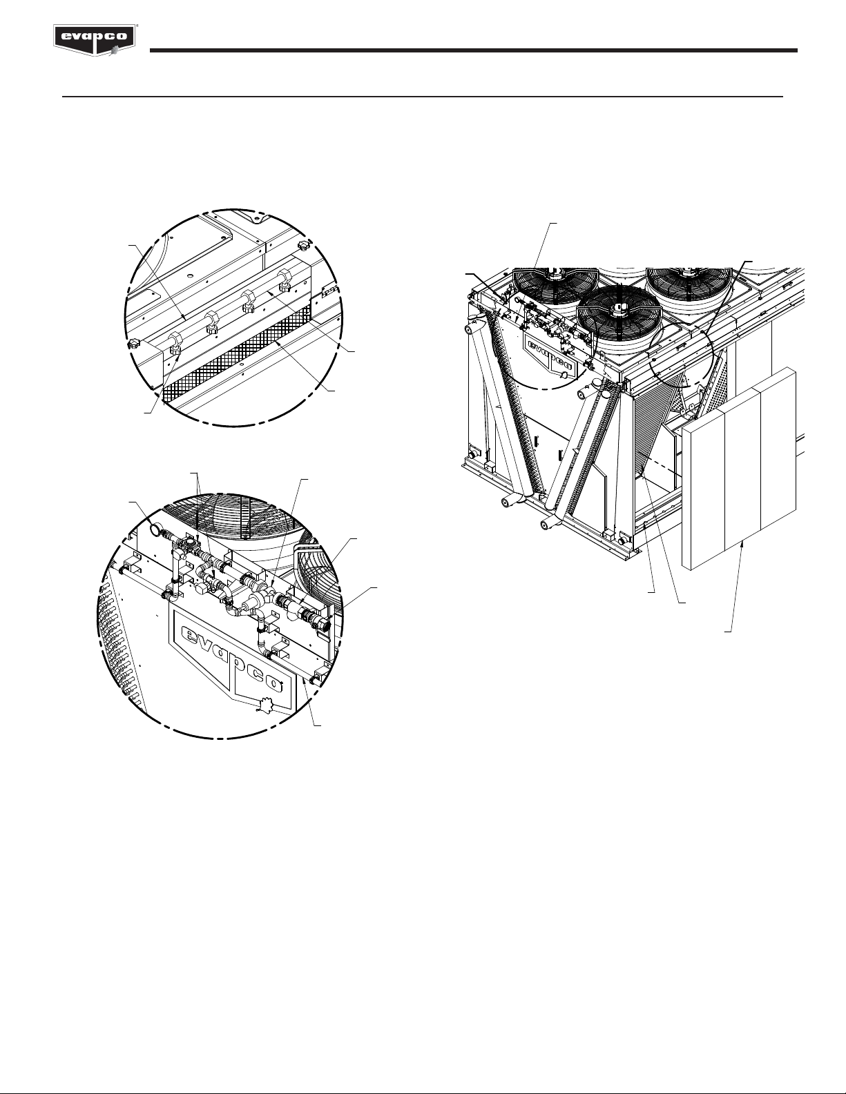
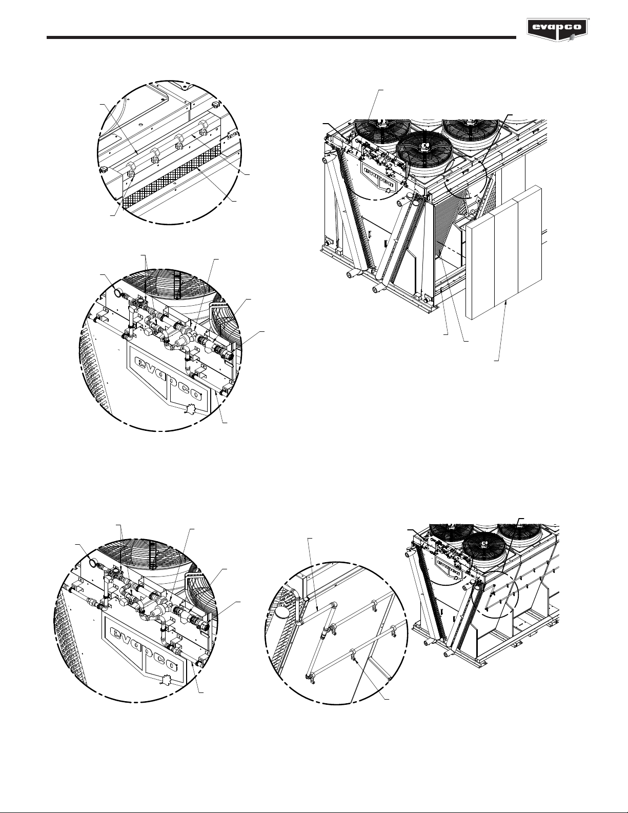
Adiabatic Pad Pre-Cooling System – If Equipped
Adiabatic pad pre-cooling systems are supplied with many dry fluid coolers, CO2gas coolers, and condensers to enhance the
performance of the unit. The below figure shows the major components of the adiabatic pad pre-cooling system.
ADIABATIC WATER
DISTRIBUTION SYSTEM
ADIABATIC DRAIN
COIL
ADIABATIC
PADS
DETAIL A
HAND
VALVE
WATER PRESSURE
REGULATOR
WYE
STRAINER
SOLENOID
VALVE
DISTRIBUTION
PIPE
WATER
BAFFLE
SPRAY BRANCH
SPRAY NOZZLE
PRESSURE
GAUGE
ADIABATIC
DISTRIBUTION
PAD
DETAIL B
AB
Figure 2 – Adiabatic Pad Pre-Cooling System Components

9
DRY, ADIABATIC AND SPRAY FLUID COOLERS, CONDENSERS & CO2GAS COOLERS
Operation (Adiabatic Pad Pre-Cooling System)
All connecting piping to the unit MUST be externally supported. The piping on the unit is not designed to bear additional piping weight.
EVAPCO recommends visually inspecting adiabatic pads and the distribution system regularly during operation and before seasonal
startup. When in operation the pads should be completely wetted (there will be a noticeable color difference). If portions of the pad are
not wetted, inspect the water distribution system for clogs.
Allow the pads to completely dry once every 24 hours with the fans running.
A water pressure regulator (WPR) is located at the end of each unit as shown in Figure 2. The WPR must be field adjusted to the water
pressure recommended on the unit data sheet/adiabatic pressure nameplate using the provided pressure gauge. The adiabatic pressure
nameplate will be located near the WPR.
When the adiabatic system is in operation and the WPR is set correctly, a small amount of water will be present in the sloped drain
channel. If it becomes necessary to adjust the water flow rate, adjust the WPR until only a small amount of water is in the sloped drain
channel but ensure that the adiabatic pads are completely wetted.
Maintenance (Adiabatic Pad Pre-Cooling System)
Rinse the adiabatic pads to remove loose sediment or dirt. If further cleaning is required use only a mild and environmentally responsible
cleaning agent that is compatible with the unit and pads materials of construction.
To access the distribution system over the adiabatic pads, remove the knobs on the top of the distribution system cover. This allows the
distribution cover to hinge down revealing the water distribution system and the distribution pad.
To remove the adiabatic pads, use the following instructions. Installation is the reverse of removal.
1. Remove the bolts on the top of the distribution system cover. This allows the distribution cover to be repositioned revealing the
distribution pad.
2. Carefully remove the distribution pad, which is the 2” tall pad positioned between the distribution tray and the large vertical
adiabatic pads.
3. Li the large vertical adiabatic pad to clear the lower support (at the bottom) and remove. It is recommended to start with the center
pad per module. This will allow for the pads adjacent to the tube sheets to clear metal brackets attached to the tube sheets.
Ensure the sloped drain channel and outlet connection are free of debris that would impede water flow by removing the adiabatic pads
and then removing the slotted sloped drain channel cover.
The pad material is a bonded cellulose UV resistant material. Refer to local codes and ordinances for disposal methods.
Remove and clean the wye strainer annually to prevent the build up of debris and decreased water flow rate to the adiabatic pads.

10
DRY, ADIABATIC AND SPRAY FLUID COOLERS, CONDENSERS & CO2GAS COOLERS
Spray Pre-Cooling System – If Equipped
Spray pre-cooling systems are supplied with many dry fluid coolers, CO2gas coolers, and condensers to enhance the performance of the
unit. The below figure shows the major components of the spray pre-cooling system.
DETAIL A
HAND
VALVE
WATER PRESSURE
REGULATOR
WYE
STRAINER
SOLENOID
VALVE
DISTRIBUTION
PIPE
DISTRIBUTION
PIPE
SPRAY NOZZLE
PRESSURE
GAUGE
DETAIL B
B
A
Figure 3 – Spray Pre-Cooling System Components
Operation (Spray Pre-Cooling System)
All connecting piping to the unit MUST be externally supported. The piping on the unit is not designed to bear additional piping weight.
EVAPCO recommends visually inspecting spray system regularly during operation and before seasonal startup. When in operation the
spray nozzles should be spraying outwards and evenly. If any nozzle isn’t operating correctly, inspect the water distribution system for clogs.
A water pressure regulator (WPR) is located at the end of each unit as shown in Figure 3. For units equipped with spray systems, the
discharge water pressure must be set once the unit is installed in the field. Refer to the technical data sheet in the factory submittal for the
WPR setting required for the submitted design conditions. The provided pressure gauge located at the discharge of the solenoid valve
can be used to validate WPR setting. There are no flow setters on the spray system. Inlet water pressure set correctly on the, WPR and a
clean water distribution system will ensure proper operation of the spray system.
NOTE: In addition to the outlined water chemistry guidelines, EVAPCO recommends that dry fluid coolers, CO2gas coolers and
condensers equipped with spray pre-cooling systems limit spray operation to peak ambient and load conditions, about 200 hours a
year, to help limit scale build-up, corrosion and to extend the life of the coil.
Maintenance (Spray Pre-Cooling System)
Clean the finned coils using the recommendations outlined under “Cleaning Hydraulically.”
Remove the spray nozzles, inspect for debris and clean as necessary.
Remove and clean the wye strainer annually to prevent the build up of debris and decreased water flow rate to the spray system.
Inlet Water (Adiabatic Pad & Spray Pre-Cooling Systems)
The water supply temperature and pressure are typically around +50°F and +50 psig, respectively for standard city water main lines. The
adiabatic pad and spray pre-cooling systems require a minimum water pressure of 50 psig at the inlet connection. The adiabatic pad and
spray pre-cooling system piping (see Figures 2 and 3) includes a water pressure regulator to enable the use of high pressure supply water,
up to 140 psig, to be connected. The inlet connection is the highest point on the EVAPCO adiabatic pad and spray pre-cooling systems,
allowing for free drainage of water, aer the soleniod valve, upon system shutoff. Please refer to the “Freeze Protection” section of this
O&M for more information on protecting the adiabatic pad and spray distribution water piping.
Normal municipal and ground water supplies are suitable for use with the adiabatic pad and pre-cooling spray systems. If other water
sources, cleaning agents, or treatments are to be used, ensure that they are compatible with all of the eco-Air product line materials of
construction including PVC, copper, brass, bonded cellulose, galvanized steel and Type 304L stainless steel.

11
DRY, ADIABATIC AND SPRAY FLUID COOLERS, CONDENSERS & CO2GAS COOLERS
Water Quality Guidelines (Adiabatic Pad Pre-Cooling Systems)
EVAPCO recommends the below outlined water chemistry guidelines applicable to ADIABATIC PAD pre-cooling systems for dry
fluid coolers, CO2gas coolers, and condensers . The water quality guidelines shown below apply to the water which is distributed over
the adiabatic pads. These guidelines are recommended to extend pad life and limit scale build up on the pads.
Property Spray Pre-Cooling System
Scenario 1 Scenario 2
pH 6.0 - 8.5 6.0 - 8.5
Conductivity (mhos/cm) <1,500 <1,000
Alkalinity as CaCO3(ppm) <250 <200
Calcium Hardness as CaCO3(ppm) <350 <250
Alkalinity + Calcium <550 <400
Chloride as Cl (ppm) <175 <150
Sulfate (ppm) <225 <200
Chloride + Sulfate <350 <300
Silica as SiO2 (ppm) <150 <150
Property Adiabatic Pad
Pre-Cooling System
pH 6.0 - 9.0
Conductivity (mhos/cm) <1,500
Alkalinity as CaCO3(ppm) <250
Calcium Hardness as CaCO3(ppm) <300
Alkalinity + Calcium <500
Chloride as Cl (ppm) <250
Sulfate (ppm) <250
Chloride + Sulfate <400
Silica as SiO2 (ppm) <150
Table 2 – Recommended Water Chemistry Guidelines for Inlet Water to Adiabatic Pad Pre-Cooling Systems
Table 3 – Recommended Water Chemistry Guidelines for Inlet Water to Spray Pre-Cooling Systems
Water Quality Guidelines ( Spray Pre-Cooling Systems)
EVAPCO recommends the below outlined water chemistry guidelines applicable to SPRAY pre-cooling systems for dry fluid coolers,
CO2 gas coolers, and condensers. The water quality guidelines shown below apply to the water which passes through the spray pre-
cooling system. Although the spray nozzles spray water away from the coils, the coils and structure of the unit will get wet when the spray
pre-cooling system is on. Thus, the water quality guidelines shown below are recommended to limit scale build-up and corrosion on the
finned tube bundles.
In addition to the water quality guidelines shown below, EVAPCO recommends designing the system for a maximum of 200 hours of
spray operation per year to help limit the possibility for scale build-up and corrosion.
*Scenario 1 applies when the entering Process Fluid or Superheated Refrigerant temperature is equal to or less than 120F.
*Scenario 2 applies when the entering Process Fluid or Superheated Refrigerant temperature is above 120F.
*For Process Fluid and Superheated Refrigerant temperatures in excess of 212F, please consult with EVAPCO.
“Process Fluid” or “Superheated Refrigerant” is the fluid that is circulated and cooled inside the coils. The water chemistry guidelines
outlined for Scenario 2 are more stringent than Scenario 1 because entering process fluid or refrigerant temperatures above 120°F can
accelerate the rate of scale formation and corrosion on the finned coil bundles when the spray pre-cooling system is operational.
If the water chemistry guidelines are not followed or if the spray pre-cooling system is run for prolonged periods of time
(>200 hours per year) or cycled excessively, excessive scale buildup is possible and is not covered under unit warranty.

12
DRY, ADIABATIC AND SPRAY FLUID COOLERS, CONDENSERS & CO2GAS COOLERS
PROCEDURE JAN FEB MAR APR MAY JUN JUL AUG SEP OCT NOV DEC
1. Check fins for clogging or debris –
monthly
2. Check unit for damage – quarterly
3. Check unit for leaks – quarterly
4. Clean the coil(s) – semi-annually
5. Check cooler coil connections for
tightness – annually
6. Check the fan blades for cracks, miss-
ing balancing weights, and vibration
– quarterly
7. Examine all wiring for signs of loose
connections or obvious damage –
quarterly
8. Lubricate fan sha bearings - Every
1000 hours of operation (or 3
months)*
9. Check belt tension and adjust
monthly inspect and grease*
10. Sliding motor base - annually or as
needed*
11.Check unit control sequence and
assure proper operation – quarterly
12.Inspect and clean unit surfaces –
annually
a. Galvanized: scrape blemishes and
coat with ZRC
b. Stainless: clean and polish with a
stainless steel cleaner
Adiabatic & Spray Units (During
Operation):
JAN FEB MAR APR MAY JUN JUL AUG SEP OCT NOV DEC
1. Check adiabatic pad and water
distribution system for damage or
incorrect pad wetting – monthly
2. Confirm water piping integrity
including flow setter adjustment. The
flow setter can be used to adjust the
amount of water distributed to the
adiabatic pads. Check to ensure holes
are unclogged – bi-monthly
3. Check spray nozzles and water
distribution system for damage and
uniform spray pattern – monthly
4. Remove and clean wye strainer –
annually
MAINTENANCE CHECKLIST
*These procedures are only for the Double Stack product line.
13
DRY, ADIABATIC AND SPRAY FLUID COOLERS, CONDENSERS & CO2GAS COOLERS
Fan System
Fan motors on the flat and V-coil units have permanently sealed bearings; therefore, no lubrication is required. The Double Stack units
with NEMA motors require their fan sha bearings to be lubricated. Be sure to verify any instructions for special motors that have been
ordered. A motor data sheet and specific motor instructions are shipped with each unit.
Please refer to The Controller User’s Manual for details about control systems.
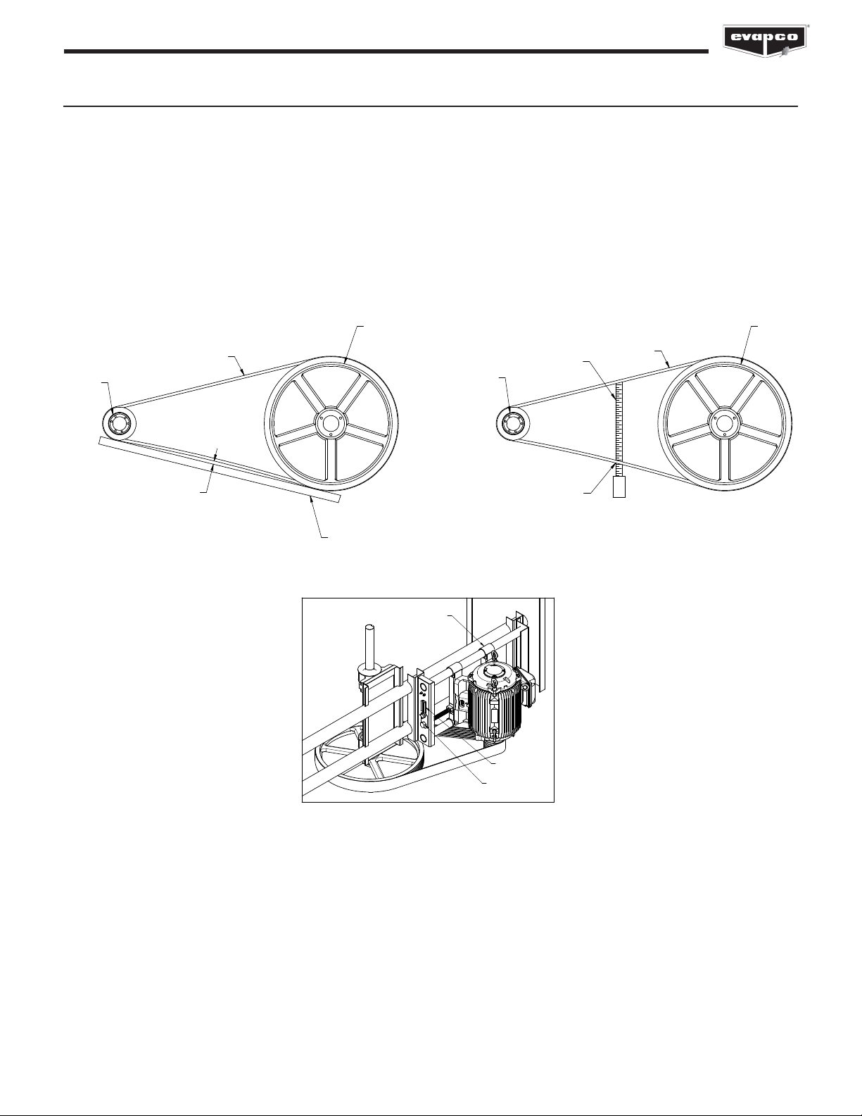
On induced dra belt driven units with internally mounted motors, a motor adjustment tool is provided. The tool will be found on the
adjustment nut. To use, place the hex end over the adjustment nut. Tension the belt by turning the nut in the appropriate direction. When
the belts are properly tensioned, tighten the lock nut
Figure 6 — Internally Mounted Motor, Double Stack
ADJUSTMENT
TOOL
ADJUSTMENT
NUT
SLIDING MOTOR BASE
Fan Belt Adjustment - Double Stack Product Line Only
The fan belt tension should be checked at start up and again aer the first 24 hours of operation to correct for any initial stretch. To
properly adjust the belt tension, position the fan motor so that the fan belt will deflect approximately 1/2” when moderate pressure is
applied midway between the sheaves. Figure 4 and Figure 5 show two ways to measure this deflection. Belt tension should be checked
on a monthly basis. A properly tensioned belt will not “chirp” or “squeal” when the fan motor is started.
Figure 4 — Method 1, Measuring Fan Belt Deflection Figure 5 — Method 2, Measuring Fan Belt Deflection
DRIVEN
SHEAVE
BELT
DRIVER
SHEAVE
STRAIGHT EDGE
1/4" TO 3/8" DEFLECTION =
PROPER BELT TENSION
DRIVER
SHEAVE
BELT
TAPE
MEASURE
DRIVEN
SHEAVE
1/4" TO 3/8" DEFLECTION =
PROPER BELT TENSION

14
DRY, ADIABATIC AND SPRAY FLUID COOLERS, CONDENSERS & CO2GAS COOLERS
Variable Frequency Drives
The use of a variable frequency drive (VFD) provides the most precise method of capacity control. A VFD is a device that converts a fixed
AC voltage and frequency and changes it into an AC adjustable voltage and frequency used to control the speed of an AC motor. By
adjusting the voltage and frequency, the AC induction motor can operate at many different speeds.
The use of VFD technology can also benefit the life of the mechanical components with fewer and smoother motor starts and built in
motor diagnostics. VFD technology has a particular benefit on evaporative cooling units operating in cold climates where airflow can be
modulated to minimize icing and reversed at low speed for de-icing cycles. Applications using a VFD for capacity control must also use
an inverter duty motor built in compliance with NEMA standard MG-1. This is a standard option from EVAPCO.
The type of motor, manufacturer of the VFD, motor lead lengths (between the motor and the VFD), conduit runs and grounding can
dramatically affect the response and life of the motor. Select a high quality VFD that is compatible with the fan motor(s) in the EVAPCO
unit(s). Many variables in the VFD configuration and installation can affect motor and VFD performance. Two particularly important
parameters to consider when choosing and installing a VFD are switching frequency and the distance between the motor and VFD, oen
referred to as lead length. Consult the VFD manufacturer’s recommendations for proper installation and configuration. The motor lead
length restrictions can vary with the vendor. Regardless of motor supplier, minimizing lead length between the motor and drive is good
practice. The motor lead length restrictions may vary with the motor vendor.
SEQUENCE OF OPERATION FOR MULTI-FAN UNITS WITH A VFD DURING PEAK LOAD
1. The VFD should all be synchronized to speed up and slow down uniformly.
2. The VFD needs to have a preset shutoff to prevent water temperatures from becoming too cold and to prevent the drive from
trying to turn the fan at near zero speed.
3. Operating below 25% of motor speed achieves very little return in fan energy savings and capacity control. Unless otherwise
stated in your factory submittal, 25% is the lowest recommended fan speed.
VARIABLE FREQUENCY DRIVE LOCKOUT NOTIFICATION
Qualified personnel should use proper care, procedures and tools when maintaining the fan/drive system in order to
prevent personal injury and/or property damage.
Identify and lockout harmful resonant frequencies.
A variable frequency drive (VFD) fan system, unlike traditional fixed-speed systems, is designed to operate between 25% (15Hz) and 100%
(60Hz) speeds, which creates an opportunity for operation where resonant frequencies exist. Sustained operation at resonant frequencies
may lead to excessive vibration, fatigue of structural components, and/or drive system noise and failure. Owners and operators must
anticipate the existence of resonant frequencies and lock out frequencies during startup and commissioning in order to prevent drive
system operational problems and structural damage. As a part of the normal start-up and commission processes, resonant frequencies
should be identified and locked out in the VFD’s soware.
The unit’s supporting structure, external piping, and accessories contribute to the overall harmonic make-up and stiffness of the system.
The choice of VFD will also have a significant influence on how the system behaves. Consequently, not all resonant frequencies can be
determined in advance at the manufacturer’s factory during final inspection and testing. Relevant resonant frequencies (if they occur) can
only be identified accurately aer the unit installation in the system.
To check for resonant frequencies in the field, a run-up and run-down test must be performed. Additionally, VFD carrier frequencies
should be adjusted to best align the VFD with the electrical system. Refer to your drive’s start-up procedures for additional information
and instruction.
The procedure of checking for resonant frequencies requires stepping through the VFD’s operating range at (2) Hz intervals from the
lowest operating frequency to full speed. At each step, pause long enough for the fan to reach steady-state. Note changes in unit
vibration during this time. Repeat from full speed to minimum speed. Should vibration-inducing frequencies exist, the run-up and run-
down test will isolate the resonant frequencies which then must then be locked out in the VFD programming.
For more details on the use of variable frequency drives, please reference the “Variable Frequency Drives” document located under
technical references, in the document library on www.evapco.com.

15
DRY, ADIABATIC AND SPRAY FLUID COOLERS, CONDENSERS & CO2GAS COOLERS
Cold Weather Operation
EVAPCO eco-Air Series air cooled equipment is well suited to operate in cold weather conditions. The lack of required water makes air
cooled equipment ideal for low ambient conditions. When the air cooled unit is going to be used during cold weather conditions, several
items need to be considered including unit layout, adiabatic pad or spray system water distribution piping (if equipped), and unit heat
transfer coils.
Unit Layout
Adequate, unobstructed air flow must be provided for both the intake and discharge from the unit. For additional information on unit
layout, please refer to EVAPCO’s Equipment Layout Manual Bulletin.
Freeze Protection
EVAPCO is not responsible for ensuring that the product is adequately protected against the heat transfer fluid freezing. If the product
has occasion to operate in close to or sub-freezing temperatures then either the heat transfer fluid should be dosed with an adequate
anti-freeze additive or provision has to be made to either manually or automatically drain the fluid from the cooler.
NOTE: Opening the air vent and drain connections as a means to fully drain the fluid from the dry cooler is not sufficient to fully empty
all the fluid and thus prevent freeze damage. In particular for large dry coolers, air pressure assisted drainage is required.
The sequence of control for a unit operating at low ambient conditions is much the same as a cooler or condenser operating under
summer conditions provided that the ambient temperature is above freezing. When the ambient temperatures are below freezing,
additional precautions must be taken to avoid the potential for damaging ice formation.
It is very important to maintain close control of the cooler or condenser during winter operation. EVAPCO recommends that the leaving
heat transfer fluid temperature NEVER be less than 6° F above the fluids freezing temperature.
If the adiabatic (optional) fluid and gas cooler or air cooled condenser is to be located in an area that experiences ice storms and freezing
conditions EVAPCO recommends the removal and dry storage of the adiabatic pads (if equipped).
NOTE: Heat tracing all adiabatic and spray water piping upstream and including the solenoid valve is required, unless the incoming
water supply lines are drained during low ambient conditions and all valves are le open (recommended). Adiabatic pad and spray pre-
cooling systems are not intended to be operated in low ambient conditions.
16
DRY, ADIABATIC AND SPRAY FLUID COOLERS, CONDENSERS & CO2GAS COOLERS
Problem Possible Cause Remedy
Overamping Fan Motors Electrical issue 1. Check voltage across all three legs of the motor.
2. Verify that the motor is wired per the wiring diagram, and connections
are tight.
3. Refer to EVAPCO’s Controller User’s Manual for further details.
Fan rotation Verify that the fan is rotating in the correct direction using visible arrow
sticker on fan cowl. If not, switch the leads so it runs correctly.
Mechanical failure If fan motor does not turn freely by hand, replace fan/motor assembly.
Motor running single- phase Stop motor and attempt to start it. Motor will not start again if single
phased. Check wiring, controls and motor.
Unusual Motor Noise Motor leads connected
incorrectly
Check motor connections against wiring diagram on motor.
Electrical unbalance Check voltage and current of all three lines. Correct if required.
Fan hitting cowl Replace fan/motor or assembly.
Defective motor Replace fan motor or assembly.
Capacity Not Reached Insufficient fluid flow Check piping system and components.
Heat transfer fluid change Compare with design fluid and adjust if required
De-energized fans 1. Verify motor has power.
2. If motor has power and is still de-energized, replace fan/motor
assembly.
Adiabatic pads not wetted Check for complete wetting of pads
1. If pads are only partially wetted, clean out water distribution pipe and
check distribution holes for clogs.
2. If pads have excessive scale they will need to be replaced.
Fouled heat Transfer surface Carefully clean fins, see page 7 for more details.
Improper Water
Distribution for
Adiabatic Pad or Spray
Pre-Cooling System
Spray nozzles not spraying
water uniformly 1. Check for clogged/fouled nozzles or distribution piping
2. Check pressure gauge to ensure correct incoming water pressure,
pressure requirements can be verified on the technical data sheet of
the submittal.
Uneven water distribution
for adiabatic pad and
pre-cooling system
Fans Not Rotating Damaged or unbalanced fan
blade or motor
Replace fan/motor assembly.
Vibration Loosely attached fan/motor
assembly
Tighten fan/ motor assembly.
Unbalanced fan (NEMA equipped units only) balance fan blade using spacers.
Replacement Parts
EVAPCO has replacement parts available for immediate shipment. Most orders ship within 24 hours from time of order!
The following pages contain exploded view drawings of all current EVAPCO eco-Air closed fluid coolers and condensers. Please use
these drawings to help identify the major parts of your unit. To order replacement parts, please contact your local EVAPCO representative
or Mr. GoodTower Service Center. The EVAPCO representative contact information is located on the unit’s nameplate or can be found
by visiting either www.evapco.com or www.mrgoodtower.com.
Additionally, your local EVAPCO representative or Mr. GoodTower Service Center can provide FREE unit inspections to help ensure your
equipment operates at peak performance regardless of the original manufacturer!
Table 4 — Troubleshooting Guidelines for eco-Air Units
Troubleshooting

17
DRY, ADIABATIC AND SPRAY FLUID COOLERS, CONDENSERS & CO2GAS COOLERS
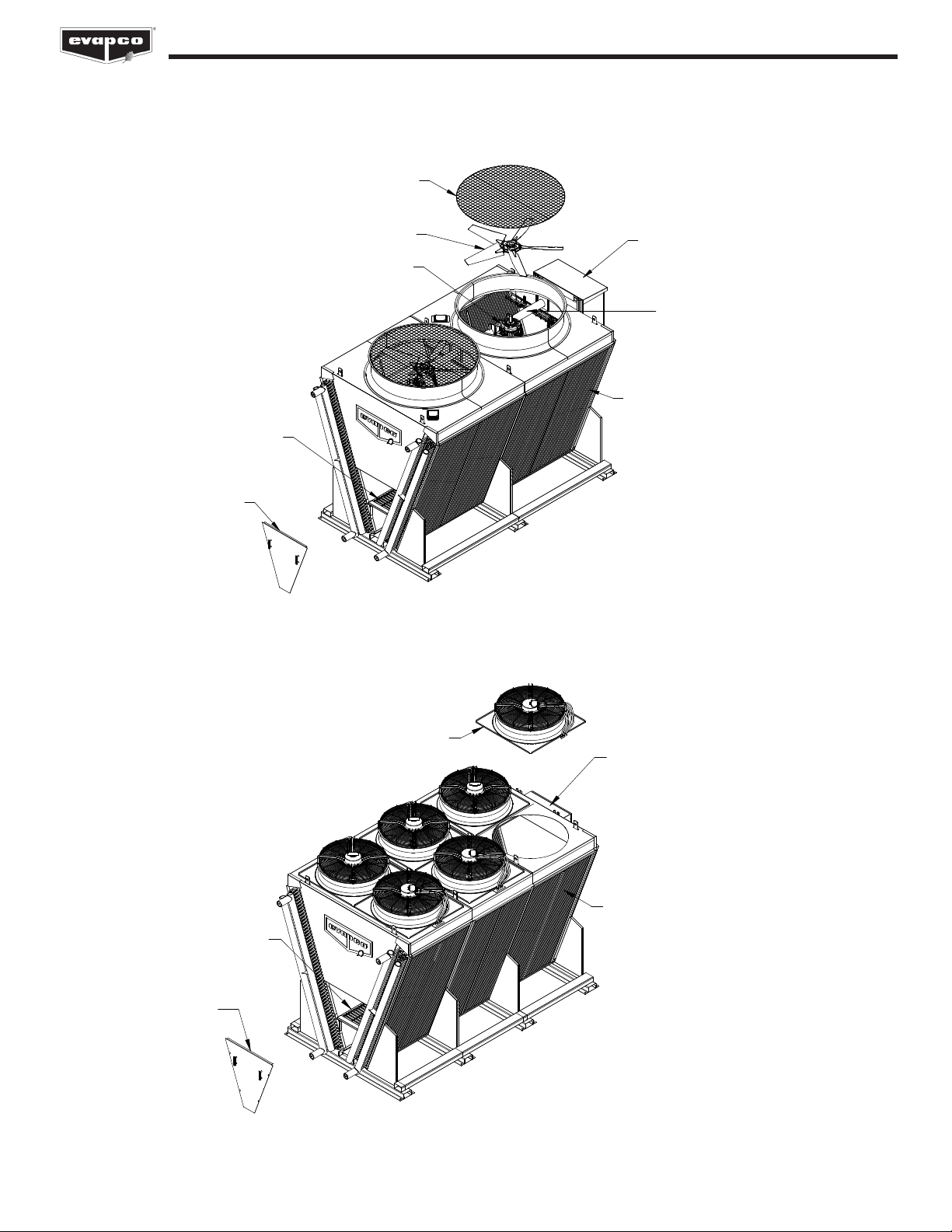
Replacement Part Drawings
eco-Air Flat Coil Configuration with NEMA Fan Motors
eco-Air Flat Coil Configuration with EC Fan Motors
COIL
FAN
SCREEN
FAN ASSEMBLY
NEMA
MOTOR
TERMINAL BOX
OR CONTROLLER
(OPTIONAL)
CASING
PANEL
MECHANICAL
EQUIPMENT
SUPPORT
EC FAN
ASSEMBLY
COIL
CASING
PANEL
TERMINAL BOX
OR CONTROLLER
(OPTIONAL)
18
DRY, ADIABATIC AND SPRAY FLUID COOLERS, CONDENSERS & CO2GAS COOLERS
FAN
SCREEN
FAN ASSEMBLY
NEMA
MOTOR
COIL
INSPECTION
PANEL
INTERNAL
STEP DECK
(OPTIONAL)
TERMINAL BOX
OR CONTROLLER
(OPTIONAL)
MECHANICAL
EQUIPMENT
SUPPORT
EC FAN
ASSEMBLY
COIL
INSPECTION
PANEL
INTERNAL
STEP DECK
(OPTIONAL)
TERMINAL BOX
OR CONTROLLER
(OPTIONAL)
eco-Air V-Coil Configuration with NEMA Fan Motors
eco-Air V-Coil Configuration with EC Fan Motors
19
DRY, ADIABATIC AND SPRAY FLUID COOLERS, CONDENSERS & CO2GAS COOLERS
eco-Air Adiabatic Pad Pre-Cooling System Components
eco-Air Spray Pre-Cooling System Components
DETAIL A
HAND
VALVE
WATER PRESSURE
REGULATOR
WYE
STRAINER
SOLENOID
VALVE
DISTRIBUTION
PIPE
DISTRIBUTION
PIPE
SPRAY NOZZLE
PRESSURE
GAUGE
DETAIL B
B
A
NOTE: If the adiabatic pad or spray pre-cooling system is provided with the “two-stage” accessory, quantity (2) solenoid valves will
be provided.
ADIABATIC WATER
DISTRIBUTION SYSTEM
ADIABATIC DRAIN
COIL
ADIABATIC
PADS
DETAIL A
HAND
VALVE
WATER PRESSURE
REGULATOR
WYE
STRAINER
SOLENOID
VALVE
DISTRIBUTION
PIPE
WATER
BAFFLE
SPRAY BRANCH
SPRAY NOZZLE
PRESSURE
GAUGE
ADIABATIC
DISTRIBUTION
PAD
DETAIL B
AB

20
DRY, ADIABATIC AND SPRAY FLUID COOLERS, CONDENSERS & CO2GAS COOLERS
eco-Air Double Stack Adiabatic Cooler with NEMA Fan Motors
eco-Air Double Stack Adiabatic Cooler with EC Fan Motors
EC FAN MOTOR ASSEMBLY
CONTROL PANEL
INSPECTION PANEL
COIL
NEMA
MOTOR
FAN
ASSEMBLY
FAN
SCREEN
MECHANICAL
EQUIPMENT
SUPPORT
POWER
DISCONNECT
COIL
INSPECTION
PANEL
This manual suits for next models
17
Table of contents
Other EVAPCO Industrial Equipment manuals


Popular Industrial Equipment manuals by other brands

GE
GE HS15-66a-9G-CUL Important safety instructions

LFA
LFA TDP 5 Assembly instructions

Dungs
Dungs FRM-NOC 100 Series instruction manual

JUKI
JUKI AW-3S instruction manual

SCHUNK
SCHUNK NSE mini 90 Assembly and operating manual

Xylem
Xylem McDonnell & Miller PSE-800-M Application, Installation, Operation, and Maintenance Manual

Eaton
Eaton PKE65/AK/XTU-65-SP Instruction leaflet

ABM International
ABM International Innova Longarm 1018 Series manual

Agilent Technologies
Agilent Technologies G1531-67000 instructions

KROHNE
KROHNE SMARTPAT COND 7200 Handbook

Balluff
Balluff BTL6-A/E500/B50 M E2/E28-KA LA Series Condensed guide

Technom
Technom Lokring MTK45 Instruction card


