Supco CPH100 User manual

Specifications
Function Range & Resolution Accuracy (% of reading)
400.0A
DC Current 4000A
± (1.8% + 3 digits)
400.0A
4000A± (2.0% + 5 digits)
4.000 AAC
40.00 AAC ± (2.5% + 10 digits)
AC Current
400.0 AAC ± (2.0 % + 5 digits)
400.0 mVDC ± (0.8% + 3 digits)
4.000 VDC
40.00 VDC
400.0 VDC ± (1.5% + 3 digits)
DC Voltage
600 VDC ± (2.0% + 3 digits)
400.0 mVAC ± (0.8% + 10 digits)
4.000 VAC
40.00 VAC
400.0 VAC
± (2.0% + 5 digits)
AC Voltage
600 VAC ± (2.0% + 5 digits)
400.0 Ω± (1.0% + 4 digits)
4.000KΩ
40.00KΩ
400.0KΩ± (1.5% + 2 digits)
4.000MΩ± (2.5% + 3 digits)
Resistance
40.00MΩ± (3.5% + 5 digits)
40.00nF (5.0% reading + 10 digits)
400.0nF (3.0% reading + 5 digits)
4.000μF
40.00μF(3.5% reading + 5 digits)
Capacitance
100.0μF(5.0% reading + 5 digits)
5.000Hz (1.5% reading + 5 digits)
50.00Hz
500.0Hz
5.000kHz
50.00kHz
Frequency
150.0kHz
(1.2% reading + 2 digits)
Sensitivity: 5~5kHz:10Vrms min.
5kHz~150kHz:40Vrms min.
@ 20% to 80% duty cycle
0.5 to 99.0% (1.2% reading + 2 digits)
Duty Cycle
Pulse width: 100µs - 100ms, Frequency: 5Hz to 150kHz
Sensitivity: 5~5kHz:10Vrms min.5kHz~150kHz:40Vrms min.
@ 20% to 80% duty cycle
-50.0 to -20. 0C7C-50.0 to 400.0C
-20.0 to 400.0C
400 to 1000C
(3.0% reading + 3 C)
400 to 1300 C
1000 to1300C(3.0% reading + 5C)
-50.0 to 0F14F-58.0 to 400.0F
0 to 400.0F
400 to 1000F
(3.0% reading + 7F)
Temp
(type-K)
(probe accuracy
not included)
400 to 2372 F
1000 to1300F(3.0% reading + 10F)
Input limits
Function Maximum Input
A AC 400A
mA DC, mA AC 200mA 250V fast acting fuse
V DC,V AC,Frequency,Duty Cycle 600V DC/AC
Resistance,Diode,Continuity, 250V DC/AC
Capacitance,Test
Temperature (°C/°F) 60V DC/24V AC
Safety
International Safety Symbols
This symbol, adjacent to another symbol
or terminal,indicates the user must refer
to the manual for further information.
This symbol, adjacent to a terminal, indicates
that, under normal use, hazardous voltages
may be present.
Double insulation
SAFETY NOTES
·Do not exceed the maximum allowable input range of
any function
·Do not apply voltage to meter when resistance function
is selected.
·Set the function switch OFF when the meter is not in use.
WARNINGS
·The dial must be set to the OFF position when installing the
batteries, or there will be no display until the dial is returned
to OFF to reset the meter.
·Set function switch to the appropriate position before
measuring.
·When measuring volts do not switch to current/resistance
modes.
·Do not measure current on a circuit whose voltage
exceeds 240V.
·When changing ranges using the selector switch always
disconnect the test leads from the circuit under test.
·Do not exceed the maximum rated input limits.
CAUTIONS
Improper use of this meter can cause damage, shock, injury or
death. Read and understand this user manual before operating
the meter. Always remove the test leads before replacing the
battery. Inspect the condition of the test leads and the meter
itself for any damage before operating the meter. Repair or
replace any damage before use. Use great care when making
measurements if the voltages are greater than 25VAC rms or
35VDC. These voltages are considered a shock hazard.
Remove the battery if the meter is to be stored for long periods.
Always discharge capacitors and remove power from the device
under test before performing Diode, Resistance or Continuity tests.
·Voltage checks on electrical outlets can be difficult and
misleading because of the uncertainty of connection to the
recessed electrical contacts. Other means should be used to
ensure that the terminals are not “live”.
·If the equipment is used in a manner not specified by the
manufacturer, the protection provided by the equipment
may be impaired.
u
n
1. AC DC AC (alternating current)
and DC (direct currrent)
2. Minus sign
3.3.
3.3.
3. 8.8.8.88.8.8.8
8.8.8.88.8.8.8
8.8.8.8 4000 count (0 to 3999)
measurement reading
4. AUTO AutoRange mode
5. ZERO ZERO mode
6. Diode test mode
7. •))) Audible Continuity
8. HOLD Data Hold mode
9. ,m,V,A,K,M, , Units of measure list
Meter Description
1. Current clamp
2. Clamp trigger
3. Rotary Function swith
4. LCD display
5. ZERO button
9. Hz/%duty button
10. COM input jack
11.V CFjack
12. Battery Cover
OPERATING INSTRUCTIONS
CPH100 HVAC CURRENT PROBE
SEALED UNIT PARTS CO., INC.
P.O. Box 21, 2230 Landmark Place, Allenwood, N.J. 08720 USA
(732)223-6644 • Fax (732)223-1617

Resistance and Continuity Measurements
1. Insert the black test lead into the negative COM
terminal and the red test lead into the positive terminal.
2. Set the function switch to the •))) position.
3. Use the multifunction MODE button to select resistance.
4. Touch the test probe tips across the circuit or component under
test. It is best to disconnect one side of the device under test so
the rest of the circuit will not interfere with the resistance reading.
5. For Resistance tests, read the resistance on the LCD display.
6. For Continuity tests, if the resistance is < 100, a tone will
sound.
Clamp size Opening 0.9" (23mm) approx
Diode Test Test current of 0.3mA typical;
Open circuit voltage 1.5V DC typical.
Continuity Check
Threshold <100;
Test current < 1mA
Low Battery Indication “ ” is displayed
Overrange Indication “OL”” is displayed
Measurements Rate 2 per second, nominal
Input Impedance 7.8M(VDC and VAC)
Display 4000 counts LCD
AC Current 50/60Hz (AAC)
AC Voltage bandwidth 50/400Hz (VAC)
General Specs for Insert
Operating Temperature 14 to 122oF (-10 to 50oC)
Storage Temperature -14 to 140oF (-30 to 60oC)
Relative Humidity 90%(0oC to 30oC); 75%
(30oC to 40oC);
45%(40oC to 50oC)
Altitude
Operating: 3000m;
Storage 10,000m
Over voltage Category III 600V
Battery Two 1.5V “AAA” Batteries
Auto OFF approx. 30 minutes
Dimensions/Weight 200x50x35mm/200g
Safety
For indoor use and in
accordance
with Overvoltage Category II, Pollution
Degree 2. Category II includes local level,appliance,
portable equipment, etc., with transient overvoltages
less than Overvoltage Cat.III
Operation
NOTICES: Read and understand all warning and
precaution listed in the safety section of this operation
manual prior to using this meter. Set the function select
switch to the OFF position when the meter is not in use.
AC Current Measurements
WARNING: Ensure that the test leads are disconnected
from the meter before making current clamp measurements.
1.Set the Function switch to the 400 or40A or 4A range.
If the range of the measured is not known, select the
higher range first then move to the lower range if
necessary.
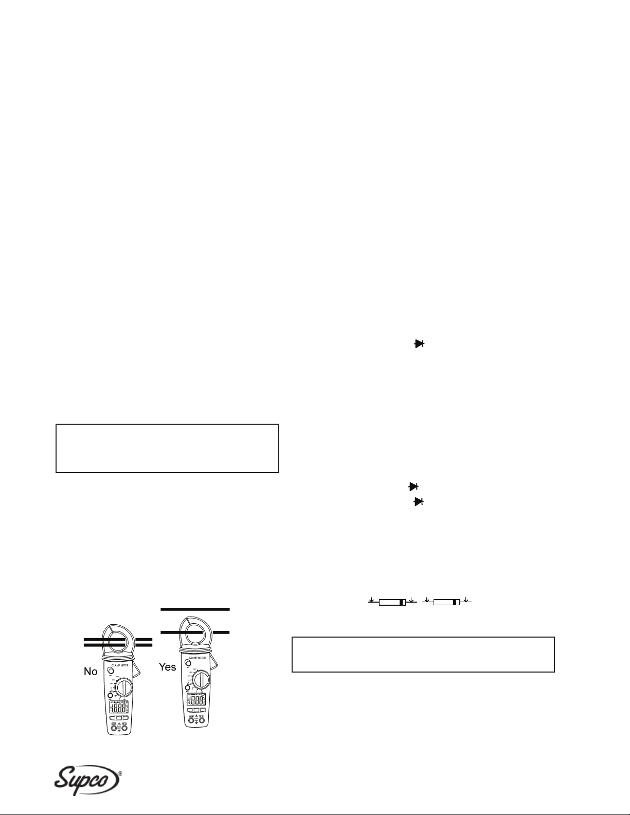
2. Press the trigger to open jaw. Fully enclose one
conductor
to be measured.
The clamp meter LCD will display the reading.
µA DC/AC CURRENT MEASUREMENTS
1. Insert the black test lead into the negative COM terminal and the
red test lead into the positive µA terminal.
2. Set the function switch to the µA position.
3. Select AC or DC with the MODE button.
4. Remove power from the circuit under test, then open up the circuit
at the point where you wish to measure current.
5. Touch the black test probe tip to the negative side of the circuit.
Touch the red test probe tip to the positive side of the circuit.
6. Apply power to the circuit.
7. Read the current in display.
Capacitance Measurements
WARNING:
To avoid electric shock, disconnect power to the unit
under test and discharge all capacitor before taking any capacitance
measurements. Remove the batteries and unplug the line cords.
1. Set the rotary function switch to the cap position.
2. Insert the black test lead banana plug into the negative (COM) jack.
Insert the red test lead banana plug into the positive (V) jack.
3. Touch the test leads to the capacitor to be tested.
4. Read the capacitance value in the display
DC/AC Voltage Measurements
1. Insert the black test lead into the negative COM terminal
and the red test lead into the positive Vterminal.
2. Set the function switch to the V position. etc., with
transient overvoltages less than Overvoltage Cat. III
3. Select AC or DC with the MODE button.
4. Connect the test leads in parallel to the circuit under test.
5. Read the voltage measurement on the LCD display.
Diode Measurements
1. Insert the black test lead banana plug into the negative COM jack
and the red test lead banana plug into the positive diode jack.
2. Turn the rotary switch to the •))) position.
3. Press the MODE button until “ “ appears in the display.
4. Touch the test probes to the diode under test. Forward voltage will
indicate 0.4V to 0.7V. Reverse voltage will indicate “OL”. Shorted
devices will indicate near 0mV and an open device will indicate
“OL”in both polarities.
Red Black Black Red
Probe Probe Probe Probe
Forward test Reverse test
SEALED UNIT PARTS CO., INC.
P.O. Box 21, 2230 Landmark Place, Allenwood, N.J. 08720 USA
(732)223-6644 • Fax (732)223-1617

Frequency or % Duty Cycle Measurements
1. Set the rotary function switch to the “Hz/%” position.
2. Insert the black lead banana plug into the negative COM jack
and the red test lead banana plug into the positive V jack.
3. Select Hz or % duty with the Hz/% button.
4. Touch the test probe tips to the circuit under test.
5. Read the frequency on the display.
Temperature Measurements
WARNING: To avoid electric shock, disconnect both test
probes from any source of voltage before making a temperature
measurement.
1. Set the function switch to TEMP.
2. Insert the Temperature Probe into the negative (COM) and the
V jacks, making sure to observe the correct polarity.
3. Select C or F with the MODE button.
4. Touch the Temperature Probe head to the part whose
temperature you wish to measure. Keep the probe touching
the part under test until the reading stabilizes (about 30 seconds).
5. Read the temperature in the display. The digital reading will
indicate the proper decimal point and value.
WARNING: To avoid electric shock, be sure the thermocouple
has been removed before changing to another measurement
function.
Data Hold
To freeze the LCD meter reading, press the data hold button.
The data hold button is located on the left side of the meter
(top button). While data hold is active, the DH display icon
appears on the LCD. Press the data hold button again to return
to normal operation.
Note:
The HOLD feature will activate when the Backlight is
turned on. Press the HOLD key again to exit Hold.
Backlight
The backlight function illuminates the display and is used when
the ambient light to too low to permit viewing of the displayed
readings. Press the button for one second to turn the
backlight on and press the button a second time to turn the
backlight off.
ZERO BUTTON
For ACA and Capacitance Zero & Offset adjustment.
Manual Ranging
The meter turns on in the autoranging mode. Press the Range
button to go to manual ranging. Each press of the range button
will step to the next range as indicated by the units and decimal
point location. Press and hold the Range button for two seconds
to return to autoranging. Manual ranging does not function in the
AC Current , Diode and Continuity check functions.
Battery Replacement
1. Remove the one rear Phillips head screw
2. Open the battery compartment
3. Replace the Requires two “AAA”batteries (UM4 R03)
4. Re-assemble the meter
SEALED UNIT PARTS CO., INC.
P.O. Box 21, 2230 Landmark Place, Allenwood, N.J. 08720 USA
(732)223-6644 • Fax (732)223-1617
Rev. 12012011
Table of contents
Other Supco Test Equipment manuals
Popular Test Equipment manuals by other brands

EL-CELL
EL-CELL PAT-Terminal-1 user manual

DuraSat
DuraSat DUR-line SF 4000 BT quick start guide

Promax
Promax GV-798+ instruction manual

easymaxx
easymaxx PFT-642 instructions

Kyoritsu Electrical Instruments Works, Ltd.
Kyoritsu Electrical Instruments Works, Ltd. 3132A instruction manual

IKALOGIC
IKALOGIC MT25C Datasheet and User Manual