Joy-it DSO-138-MINI User manual

DSO138-MINI
Mini digital oscilloscope
Joy-IT powered by SIMAC Electronics GmbH - Pascalstr. 8 - D-47506 Neukirchen-Vluyn - www.joy-it.net

Dear customer,
thank you for choosing our product. In the following, we will show you what
to pay attention to during commissioning and use. If you encounter any
unexpected problems, please feel free to contact us.
The new Joy-IT oscilloscope set DSO-138-Mini is the improved successor
of the DSO-138, which is the ideal complement to the multimeter and can
also be used mobile with the help of an optionally available battery. The
DSO-138-Mini is ideal for ambitious tinkerers, because it allows you to
measure and evaluate time-dependent signals without having to invest in
more expensive hardware. Our device has all the basic functions of a digital
storage oscilloscope, including: automatic/manual trigger mode, single-
shot recording with signal analysis and restoring stored signal waveforms.
1. GENERAL INFORMATION
2. OVERVIEW
Number of channels 1
Analog bandwith 0 - 200 kHz
Sensitivity range 10 mV/div - 5 V/div
Resolution 12 bit
Maximum input voltage 50 VPk
Coupling DC, AC, GND
Max. real-time sampling rate 1 MSa/s
Trigger types Rising/falling edge
Sensitivity deviation <5 %
Input impedance 1 MΩ
Timebase 10 µs/Div - 500 s/Div
Record length 1024 Points
Trigger modes Auto, Normal, Single
Trigger position 1/2
Display 2,4" TFT LCD - 320x240
Voltage & power supply 3.5 V - 6 V DC, 120 mA @5 V
Trigger status
Trigger indicator
Rising/falling edge
Trigger modeTimebase
Coupling
Sensitivity
Vertical indicator
Active mode
Horizontal indicator

First, connect a microUSB cable to the power supply input as shown in the
following picture. The DSO138-Mini requires approx. 120 mA at a voltage of
5 V. Make sure that your power supply is rated for this. Now also connect the
lead to the signal input of your device.
Aer you have established the power supply, the device starts
automatically. As an alternative to the microUSB power supply, a 3.7 V
lithium-ion battery can also be used for mobile use. For more information
on battery-powered use, see Chapter 6 - Connecting an external battery
unit.
To check the function of the device, you can connect the test line to the
test signal. Connect the red test lead for this purpose. The black test lead
remains unconnected, as measurements are only made in the circuit of the
test device. The ground connection is already given by the circuit board of
the device. A signal of 1 kHz is output via the test signal.
3. SETUP

As soon as the device is supplied with voltage, it starts up automatically.
The sensitivity and the coupling can be adjusted via the switches next to
the signal input:
CPL: INPUT COUPLING
Here the coupling mode can be set to DC, AC or ground. With DC coupling,
all components of the input signal are displayed. With AC coupling, the DC
portion of the signal is suppressed and the signal is displayed centered at
the vertical ground reference.
With GND coupling, all components are ltered to display the zero line.
SEN1: SENSITIVITY
The sensitivity can be set between 10 mV, 0.1 V and 1 V. The sensitivity here
indicates the vertical scale.
SEN2: SENSITIVITY (MULTIPLICATOR)
An additional multiplier for the sensitivity between X1, X2 and X5 can be set
here. The multiplier can be used to reduce the signal in order to display a
larger section on the screen.
The coupling and the sensitivity are additionally also shown on the display:
4. CONFIGURATION
Coupling
Sensitivity
(SEN1 x SEN2)

All other conguration options can be set using the buttons below the
display:
THE FOLLOWING CONFIGURATIONS CAN BE MADE:
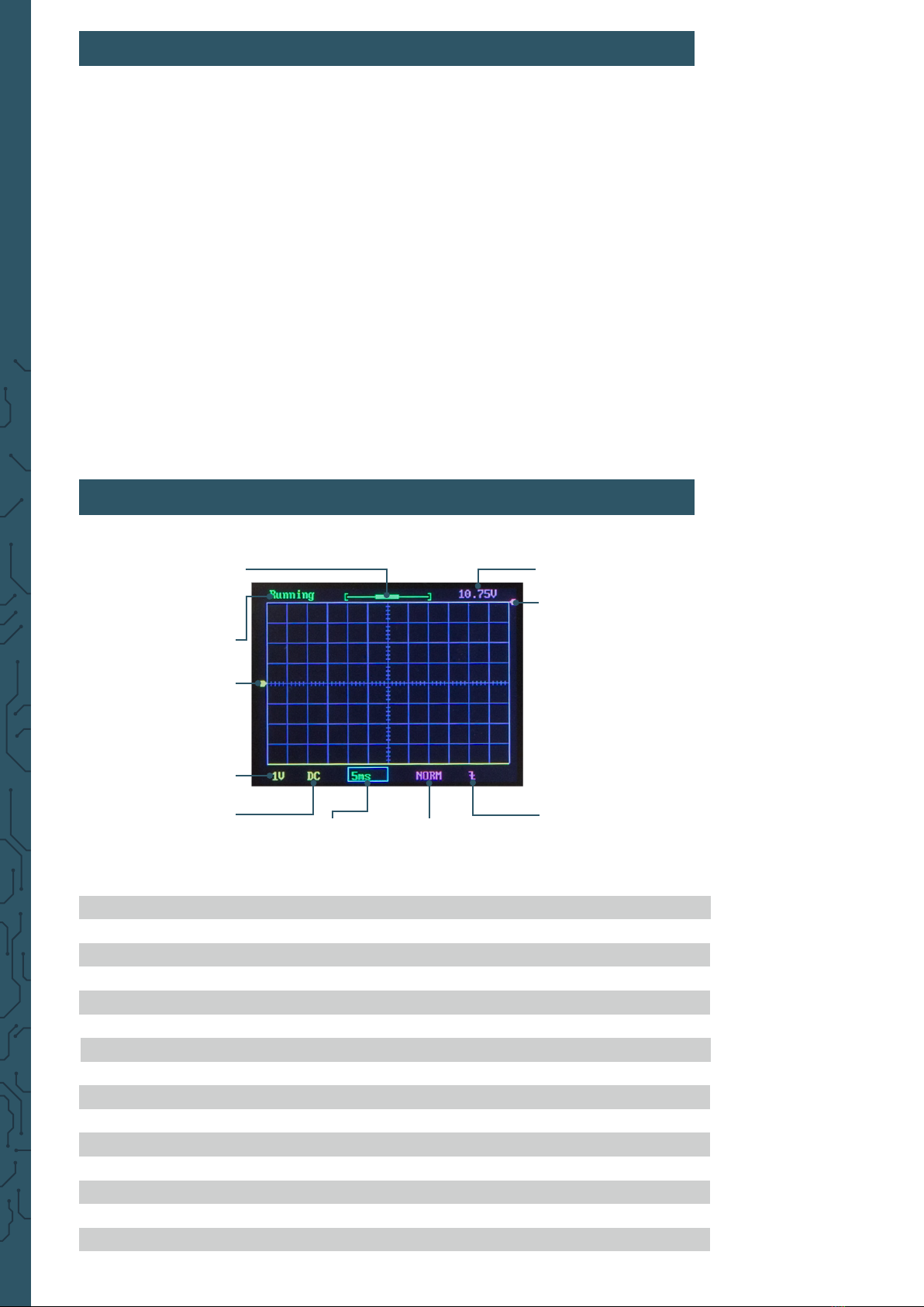
DISPLAY MODE
The active mode can be set between Running and Hold. Running describes
the normal measuring mode. Hold pauses the current measurement at the
current time. The display mode can be changed with the OK key.
TIMEBASE
The time base can be set between 0.1 s, 0.2 s, 50 ms, 20 ms, 10 ms, 5 ms, 2
ms, 1 ms, 0.5 ms, 0.2 ms, 0.1 ms, 50 µs, 20 µs and 10 µs and indicates the
horizontal resolution.
To set the time base, the time base must rst be selected via the SEL key.
Aerwards, the time base can be set to the corresponding value via the "-"
key and the "+" key.
TRIGGERMODUS
The trigger mode can be set between Auto, Normal and Single and describes
when a measurement sequence is triggered. In Auto mode, the recording is
executed permanently. In Normal mode, the recording is held as soon as no
trigger signal is present. In Single mode, the recording is held immediately
as soon as a trigger signal is detected.
To set the trigger mode, the trigger mode must rst be selected via the SEL
key. Aerwards, the mode can be set to the corresponding mode via the "-"
key and the "+" key.
RISING/FALLING EDGE
The signal is triggered by an edge. The measuring sequence can be triggered
either by a rising or a falling edge.
To set the edge, the edge mode must rst be selected via the SEL key. Then
the mode can be set to the corresponding mode via the "-" key and the "+"
key.
SHOW/HIDE MEASUREMENT VALUES
Additionally, it is possible to show or hide the measured values, such as the
frequency or the voltage values. To do so, press and hold the OK key for
three seconds.

Under certain circumstances it may be necessary to open the device, for
example to connect an external battery, to adjust the trimmers or to expose
the other, optional connections.
To do this, rst, open the housing by removing the screws on the back of the
device:
5. OPENING THE DEVICE
Now remove the cover from the housing and pull the motherboard o the
device so that only the display unit remains in the housing.

If necessary, the display can additionally be removed by removing the
screws on the front of the device. Aerwards, the display can be removed
from the front of the case.

The DSO138-Mini can also be powered by a 3.7 V lithium-ion battery as an
alternative to the power supply via the micro USB connector.
Attention! An external battery unit must either be charged externally or a
JYE118 module must also be installed. Aer that, internal charging is also
possible.
First, open your device as described in Chapter 5 - Opening the device.
Aer you have separated the mainboard from the display unit and removed
it from the housing, you can now connect a battery to the mainboard.
The housing can then be reassembled. The voltage supply via the connected
battery unit can now be controlled from the side via the "Bat-Switch".
6. CONNECTING AN EXTERNAL BATTERY UNIT

If necessary, the capacitor trimmers can be adjusted to calibrate the
instrument. To do this, rst, open the device as described in Chapter 5 -
Opening the device.
Aer you have removed both the mainboard and the display from the
housing, you can rst place the display unit back on the mainboard. The
two trimmer capacitors are now freely accessible.
Now connect the lead to the connector of the device and connect the red
test clamp to the test signal. The black test clamp remains unconnected.
Now set the switch [SEN1] to 0.1 V and the switch [SEN2] to X5. The [CPL]
switch can be set to AC or DC.
Now set the time base to 0.2 ms. The test signal should now be displayed
similar to the following gure:
7. TRIMMER CALIBRATION
C6 C4
Testsignal

Now adjust the trimmer capacitor C4 with a screwdriver so that an even,
rectangular waveform is created.
Now set the switch [SEN1] to 1 V and the switch [SEN2] to X1. Now repeat the
setting procedure with capacitor C6. You can use the following illustrations
as a guide for calibrating the trimmer capacitors:
Aer you have adjusted the trimmers, you can put the display unit and the
mainboard back into the housing.
Not set properly
Not set properly
Correctly set

Alternatively, an external trigger signal can also be connected to the device.
To do this, rst, open the device as described in Chapter 5 - Opening the
device.
Aer you have removed both the mainboard and the display from the
housing, you can rst place the display unit back on the mainboard. The
additional connections are now accessible on the display unit.
Aer you have used the desired connections, the device can be put back into
the housing.
RESET - Short-circuit both pins to reset.
3,3 V
PB15 - External trigger signal
Ground, 3,3 V
8. EXTERNAL TRIGGER CONNECTION, RESET & OTHER CONNECTIONS

VERTICAL POSITION ALIGNMENT
Move the cursor to the vertical position indicator via the [SEL] key. Now
press and hold the [OK] key for three seconds and follow the instructions on
the screen.
SHOW/HIDE MEASUREMENT VALUES
To show or hide the measured values, move the cursor to the time base
using the [SEL] key. Now press and hold the [OK] key for three seconds.
SAVE WAVEFORM
Press the [SEL] key and the [+] key simultaneously. The currently displayed
waveform is stored in the EEPROM. Previously stored data will be
overwritten.
LOAD WAVEFORM
A previously stored waveform can be loaded from the EEPROM by
simultaneously pressing the [SEL] key and the [-] key.
CENTER HORIZONTAL POSITION
To center the horizontal position, move the cursor to the horizontal position
indicator via the [SEL] key. Now hold down the [OK] key for three seconds.
CENTER TRIGGER LEVEL
Select the trigger level via the [SEL] key and then hold down the [OK] key
for three seconds. The trigger level is now automatically set to the average
value of the signal amplitude.
SEND WAVEFORM
Press and hold the [SEL] key for three seconds to send the waveform data
in text form via serial port J5. The data is transmitted in the format 8N1 and
with a baud rate of 115200.
TOGGLE TEST SIGNAL AMPLITUDE
Move the cursor to the rising/falling edge setting via the [SEL] key. Now
press and hold the [OK] key for three seconds to set the test signal amplitude
to 3.3 V or 0.14 V. The amplitude is displayed via the symbol. The
amplitude is displayed here via the symbol in the upper screen area.
CALIBRATE ANALOG GAIN
Move the cursor to the trigger source setting (Int/Ext) via the [SEL] key. Now
press and hold the [OK] key for three seconds to start the calibration. Now
follow the instructions on the screen.
9. ADDITIONAL FUNCTIONS

Keep the operating instructions and safety instructions in a safe place! If
the device is passed on to third parties, it is essential that these are also
handed over.
Only use this device for the respective area of application and in accordance
with the operating instructions. Follow our instructions for assembly and
use. Read the instructions completely before you start using the device.
Before commissioning, make sure that the available mains voltage
corresponds to the specied mains voltage. The specied mains voltage
must not be deviated from under any circumstances during use.
The device is only intended for use in dry rooms, it must not get wet or
damp.
This product is not a toy and therefore must not be used by children.
Therefore, always keep the product away from children and store it in a
place inaccessible to children.
The device is only suitable for measuring extra-low voltages below 50 V. It
must not be connected to higher voltages.
10. SAFETY INSTRUCTIONS
Please be sure to observe the following safety instructions. Failure to
observe the safety instructions may result in serious injuries due to electric
shocks / heat generation / re, which may also lead to death:

www.joy-it.net
SIMAC Electronics GmbH
Pascalstr. 8, D-47506 Neukirchen-Vluyn
Published: 05.03.2021
12. SUPPORT
We also support you aer your purchase. If any questions remain or
problems arise, we are available to assist you via e-mail, telephone and
ticket support system.
E-Mail: service@joy-it.net
Ticket-System: http://support.joy-it.net
Phone: +49 (0)2845 98469 – 66 (9 - 17 Uhr)
For more information visit our website:
www.joy-it.net
11. OTHER INFORMATION
Our informaon and take-back obligaons under the Electrical
and Electronic Equipment Act (ElektroG)
Symbol on electrical and electronic equipment:
This crossed-out trash can means that electrical and electronic equipment
does not belong in the household trash. You must hand in the old equipment
at a collecon point. Before handing in, you must separate used baeries and
accumulators that are not enclosed in the old device from the old device.
Return opons:
As an end user, when you purchase a new appliance, you can return your
old appliance (which performs essenally the same funcon as the new one
purchased from us) for disposal free of charge. Small appliances with no
external dimensions larger than 25 cm can be returned in normal household
quanes, regardless of the purchase of a new appliance.
Possibility return to our company locaon during opening hours:
SIMAC Electronics GmbH, Pascalstr. 8, D-47506 Neukirchen-Vluyn
Possibility return in your area:
We will send you a parcel stamp with which you can return the device to us
free of charge. To do this, please contact us by e-mail at service@joy-it.net or
by phone.
Packaging informaon:
Please pack your old device securely for transport. If you do not have suitable
packaging material or do not wish to use your own, please contact us and we
will send you suitable packaging.
Other manuals for DSO-138-MINI
1
Table of contents
Other Joy-it Test Equipment manuals