Updated: 10 February, 2010 Page 4 Ref: REI-55VGF2
1. Introduction
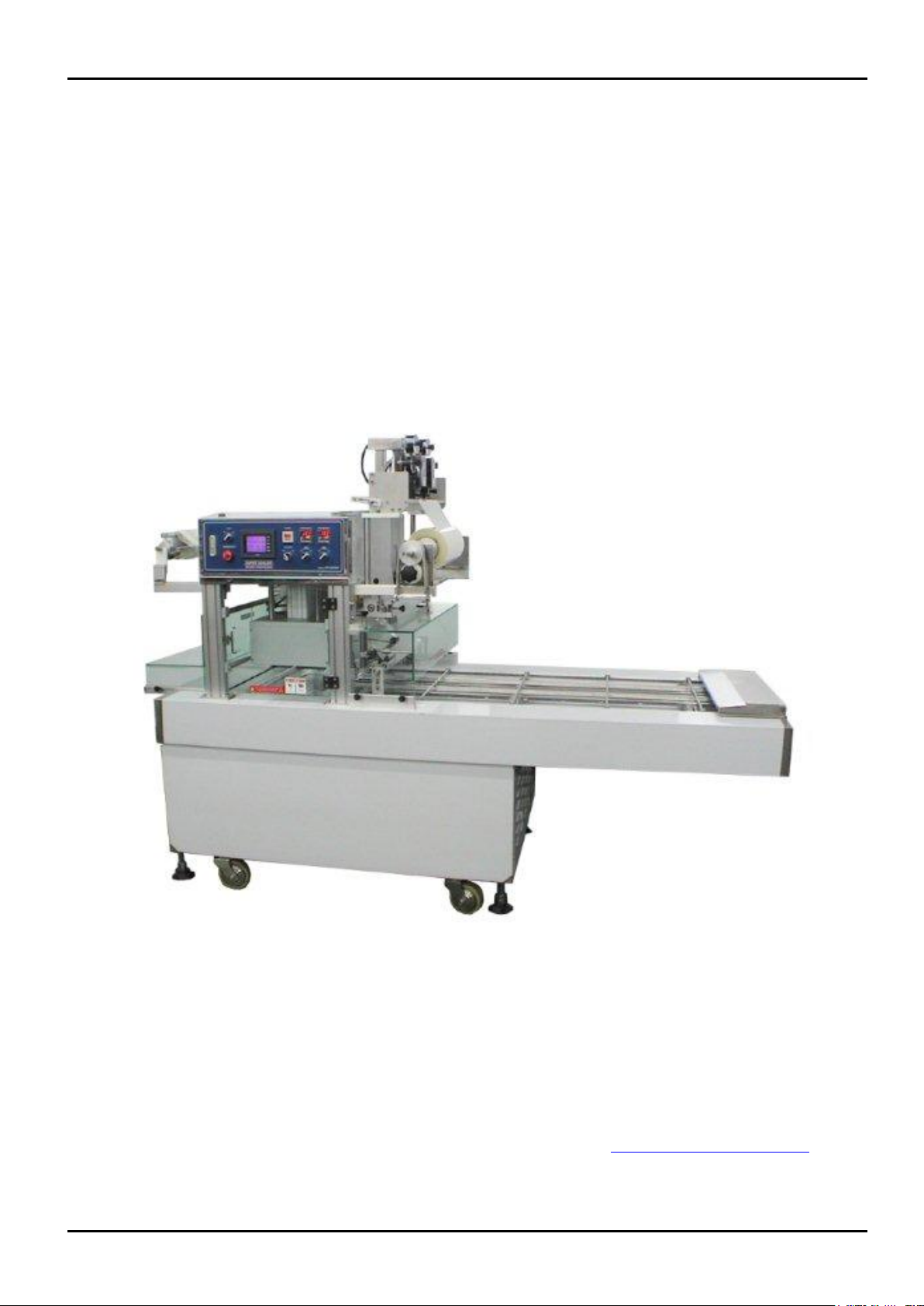
Super Sealer REI-55VGF linear sealing machine models are ideal application for MAP (Modified Atmosphere Packaging) food
process from small to medium or large batch operations. With unique MAP sealing mould design for different products, food’s
shelf life can be efficiently prolonged.
The machine offers superior quality machine suitable for small and medium food processing factories and available for any
sealable cups and trays such as PP, PE, PET, PVC, Card Board, or Foil Trays.
By utilizing some of the options below, a Super Sealer Rotary Sealing machine can also offer complete and fully automated
solution for different food processing applications including dips, homus, pate, yoghurt, cheese, fruit paste, antipasto, cup
water, milk, etc.
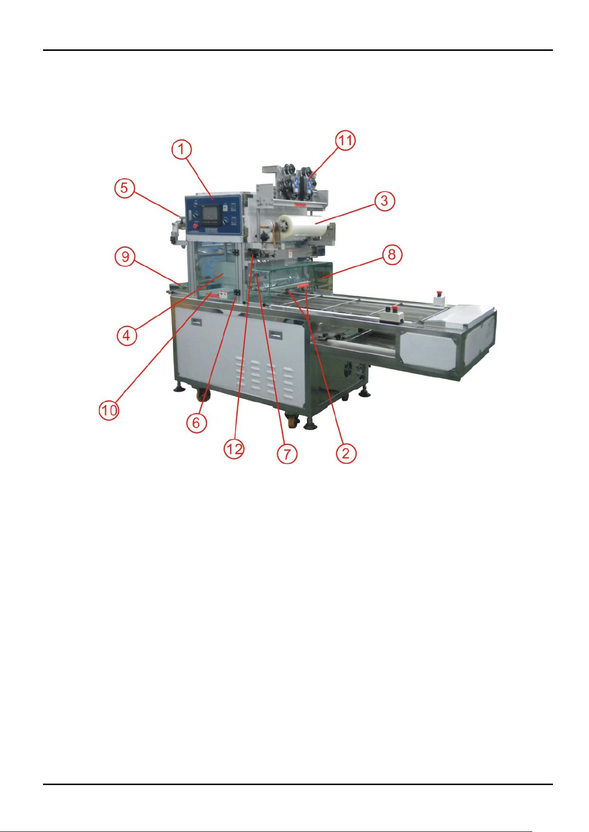
MAIN FEATURES
Up to about 8 cycles (With MAP) &16 cycles (Without MAP) per minute.
Stainless steel frame construction and components are standard.
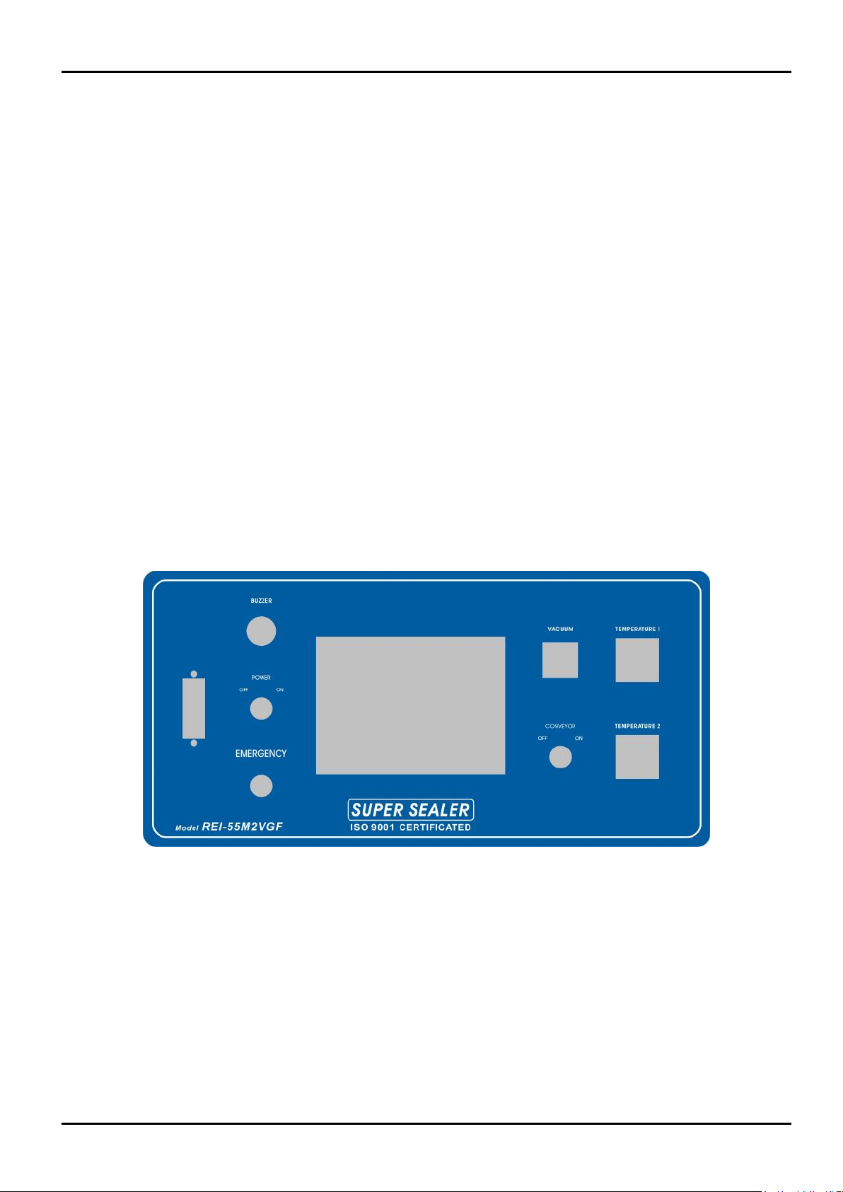
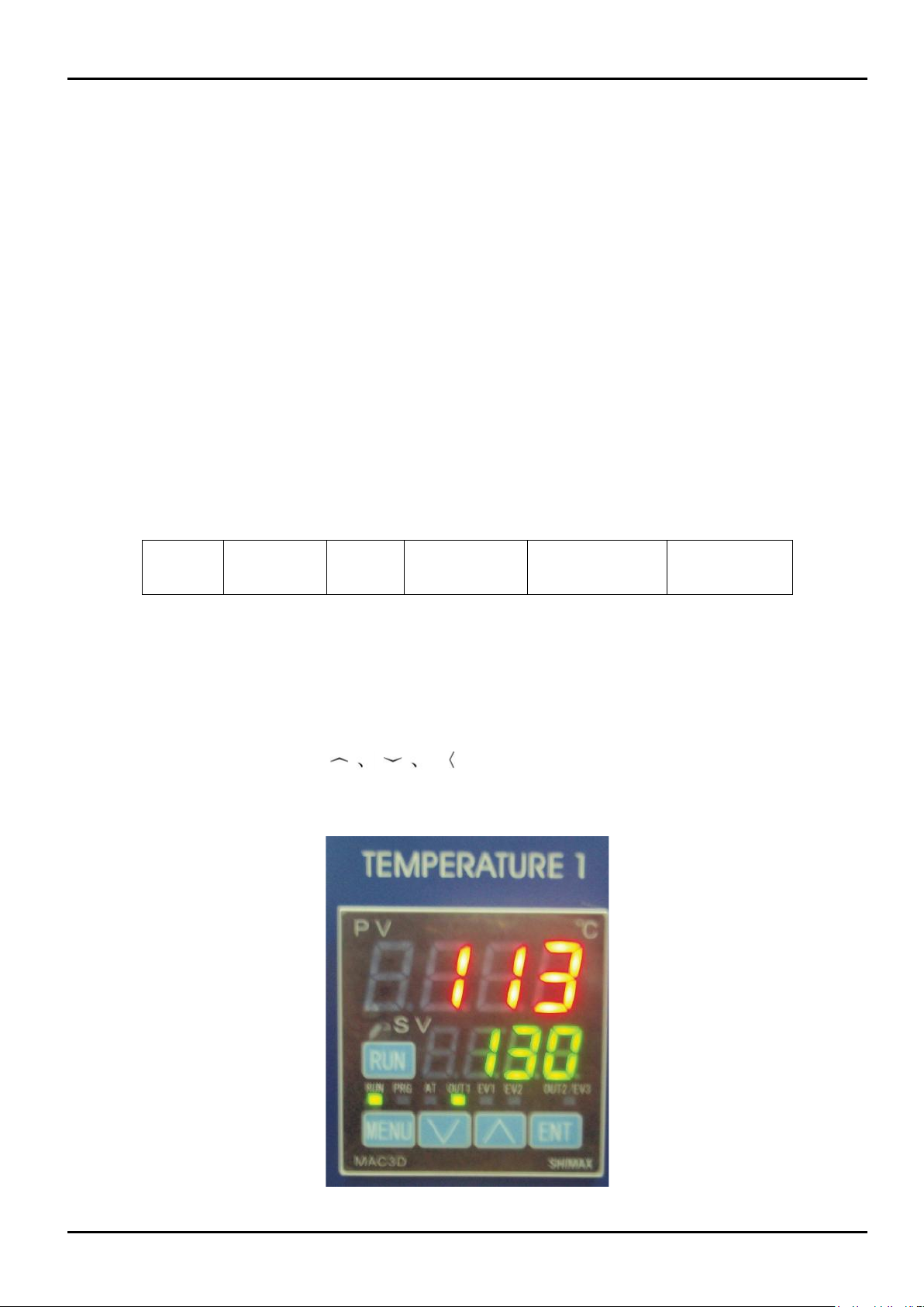
PLC Controlled and Touched Screen Panel design.
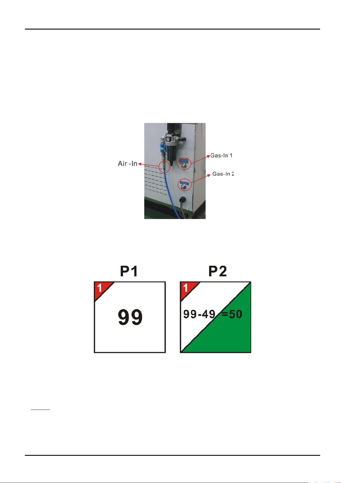
Requires pneumatic compressed air supply (600KPa, 400~600L/Min).
Sealing moulds can be exchangeable for different tray for about 15 minutes only.
Safety Features –gearless construction and emergency button.
Container Photo Sensor or Automatic option.
Film Sensor or Encoder option.
Film Border from 2mm (standard is 3mm).
OPTIONALS
Options are not a simple “plug and play” type. The machine’s physical construction and the control system are predefined
as per customer requirements and specifications.
Vacuum & Gas Flushing (MAP)
Gas Flushing (Vacuum less)
Date Printer/Coder (hot ink manual) Interchangeable Mould
Cup Denester/ Drop
Auto-Fill (Liquid, Heavy Liquid, Powder, Solid products)
Auto-Capping
Auto-Container Discharge (Infeed)
Discharger (Product Outfeed)
Precut Lid Applicator
Pull Tab Cutter
Load Cell/Scale