Superior Signal AccuTrak VPE-2000 User manual

Model VPE-2000
User’s Manual
Superior Signal Company LLC
www.SuperiorSignal.com

AccuTrak VPE-2000
2
Contents
INTRODUCTION AND GENERAL DESCRIPTION...............................................................................3
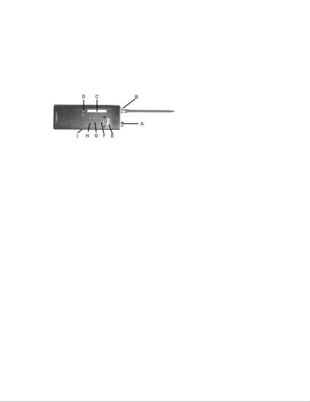
PHYSICAL DESCRIPTION........................................................................................................................4
BATTERY INSTALLATION ......................................................................................................................5
GETTING STARTED (A CONDENSED GUIDE FOR THOSE WHO HATE TO READ
MANUALS) ...................................................................................................................................................6
LEAK DETECTION.............................................................................................................................................6
TOUCHPROBE APPLICATIONS............................................................................................................................7
PRINCIPLE OF OPERATION....................................................................................................................8
OPERATION.................................................................................................................................................9
USING THE MODES............................................................................................................................................9
Setting the Sensitivity: .................................................................................................................................9
Setting the Volume: .....................................................................................................................................9
Selecting the Sensor: .................................................................................................................................10
Adjusting the Display: ...............................................................................................................................10
“Hidden” MODE Options.........................................................................................................................10
APPLICATIONS OVERVIEW..................................................................................................................11
1. AIRBORNE APPLICATIONS (EXTERNAL SOUNDS)........................................................................................11
Leaks..........................................................................................................................................................11
Methods of reducing background noise interference. ...............................................................................12
Frequency Selection (Airborne) ................................................................................................................13
Recording overall system noise. ................................................................................................................13
2. TOUCHPROBE APPLICATIONS (INTERNAL SOUNDS,BEARINGS,VALVES,STEAM TRAPS). ...........................14
Frequency Selection (touchprobe): ...........................................................................................................14
Steam Traps...............................................................................................................................................14
Valves ........................................................................................................................................................15
Bearings and Moving Machinery ..............................................................................................................15
Charting your results.................................................................................................................................16
Vibration....................................................................................................................................................17
OTHER APPLICATIONS..........................................................................................................................18
ELECTRICAL ARCING......................................................................................................................................18
BELTS.............................................................................................................................................................18
DUCTWORK....................................................................................................................................................18
HYDRAULICS..................................................................................................................................................18
SOUND GENERATOR...............................................................................................................................18
IDEAS ON HOW TO PROFIT FROM ACCUTRAK.............................................................................19
CARE AND SERVICE................................................................................................................................20
CALIBRATION .................................................................................................................................................20
WARRANTY....................................................................................................................................................21

AccuTrak VPE-2000
3
Introduction and General Description
Congratulations on your purchase of the AccuTrak model VPE-2000 ultrasonic
inspection system. You have invested in the most sophisticated and
technologically advanced ultrasonic test instrument available. The AccuTrak
model VPE-2000 is an excellent tool for leak detection, but it also does much
more. This instrument will accurately test steam traps and valves for internal
leaks! It will allow you to accurately record the ultrasonic sound signatures of
bearings and other moving machinery to gauge the extent of wear, and predict
failure BEFORE it occurs!
We at Superior Signal have dedicated thousands of man hours developing the
AccuTrak which is the first ultrasonic detector to offer digital controls and
displays. No other instrument, even those costing thousands of dollars, can
produce such accurate readings, and consistent results in repeatable tests.
The internal signal processing is performed by a patented process with additional
patents pending. This circuitry assures the reduction of "noise", a true
translation of ultrasonic frequencies, and the most precise and consistent
readings available.
Use your new instrument to detect pressurized gas leaks of compressed air,
refrigerant, steam, nitrogen, or even vacuum. The touchprobe sensor allows you
to detect the slightest flow abnormality in pumps, steam traps and valves.
Mechanical wear in bearings and other moving machinery can also be quickly
identified. Overall system noise can be recorded and compared to previous
readings for an accurate record of increasing noise patterns.
This booklet contains information necessary to use and interpret sounds with
your AccuTrak. To eliminate any future frustration, we recommend you take a
few minutes to read this manual and understand the operation of your new
instrument. Again, congratulations. We are sure you will be pleased with your
choice.

AccuTrak VPE-2000
4
Physical Description
The following picture describes the various controls, adjustments and features of
the VPE-2000.
A. Airborne sensor: Detects external ultrasonic sound which travels through
air vibration. Examples... pressurized gas leaks, vacuum leaks, external
system noise. The sensor horn accepts various waveguides and
attachments.
B. Touchprobe sensor: Detects internal system sounds. Examples... internal
valve leaks, bearing wear, faulty steam traps.
C. Intensity display meter: Shows relative strength of detected signal in a
bargraph format.
D. Power button: Turns the instrument on or off.
E. Alphanumeric Display (A.N.D.): Level/Mode Indicator, Displays active
mode, current mode setting, and numeric intensity reading. Available mode
options include; Air, Probe, Display, Volume, and Sensitivity. This display
also indicates when battery power is low.
F. Mode Select Button: Scrolls through mode options to be adjusted and/or
selected.
G. UP Adjustment (“”): Increases setting or scolls through options in a
particular mode.
H. Down Adjustment (“”): Decreases setting or scrolls through options in a
particular mode.
I. Headphone Jack: Insert Headphone connector.

AccuTrak VPE-2000
5
Battery installation
There is a sliding battery door located on the back of the VPE-2000.
Turn the unit over so that the controls are facing the floor, and the
sensor is facing away from your body.
At the opposite end from the sensors (the end closest to you) there is
a sliding panel.
Apply minimal pressure to the center of the panel and slide it towards
you exposing the battery compartment.
Install a new 9 volt battery noting the (+) and (-) positions which are
indicated on the inner label.

AccuTrak VPE-2000
6
Getting Started (A condensed guide for those who
hate to read manuals)
OK, here it is. A quick overview of the AccuTrak VPE-2000 written for those who
will probably read nothing else. This will give you a basic understanding of the
unit’s operation and function, however we STRONGLY recommend that you
read the complete manual. Or, at the very least, continue to read the following
section concerning the principles of operation.
Leak Detection...
Use the airborne sensor for detecting pressurized gas leaks and vacuum leaks.
Remember, leaks must be turbulent to detect ultrasonically.
1. Insert the headset jack into the plug on the side of the instrument (I.), and
push the power button (D.).
2. Depress the mode select button (F.) until the alphanumeric display (A.N.D.)
reads “AIRH” (This stands for airborne sensor at high ultrasonic frequency)
then press the “”or “”to activate the airborne sensor (A.). “AIRL”, or Low
frequency ultrasonic is also available, and is activated the same way. Once
activated you will begin to hear a translation of any ultrasonic sound present
in test area, and the LED bargraph meter will display the strength of the
corresponding signal. The highest LED will hold its place for 5 seconds
before resetting its position. This will help guide you toward the leak, where
the sound is most intense. The instrument always resets itself so that
sensitivity is the active mode. If the LED bargraph meter is at maximum,
reduce the sensitivity by simply pressing ““ until it reads “10” or less, then
continue.
3. To adjust the volume, press the mode button once. The A.N.D reads “VOL”.
Then use the “”and “”buttons to make the adjustment. The
alphanumeric display will read “V 000”. Volume, as with all numerical values,
has a range of 0 to 255.
4. Listen for the leak. A gas leak will sound like a harsh rushing noise, or high
intensity hiss. This sound will increase as the instrument is drawn toward the
leak point, and will clearly disappear as the sensor is turned away.
5. For more detailed information on specific applications, refer to page 10 of this
manual.

AccuTrak VPE-2000
7
Touchprobe applications...
Use the touchprobe to detect internally generated ultrasound. These
applications include... steam traps, valves, and bearings.
1. Insert the metal touchprobe into its port (B.) on the nose of the VPE-2000.
The probe should be snug so it can not rattle, however, do not overtighten.
Depress the mode select button (F.) until the display reads “PrbH, PrbL or
PrbS”. This stands for Probe high / low ultrasonic range, and Probe Sonic.
Press the “” and “” to activate the touchprobe selection.
2. Making a firm contact, touch the tip of the probe to the item being tested.
Apply just enough pressure to make a good contact. You will hear a clear
translation of the internally generated ultrasonic sound.
3. Listen for fluid leaks in valves, continuous flow or non-cycling in steam traps,
and knocking or scraping in bearings.
4. The VPE-2000 always defaults back to Sensitivity as the active mode,
therefore if your readings are off the scale simply press the “”to reduce the
reading to within the range of the instrument. The A.N.D. will display the
active sensor and current sensitivity setting before it begins to make the
adjustments.
5. To adjust the volume, press the mode button once. The A.N.D. reads “VOL”.
Then use the “” and “” buttons to make the adjustment. The
alphanumeric display (A.N.D.) will read “V000”. Volume, as with all numerical
values, has a range of 0 to 255.
6. When testing bearings or machinery vibration, record your sensitivity setting,
and use the reading on the A.N.D. as a baseline for future readings. Now
you can compare the wear patterns to future tests, and other similar
equipment.
7. For more specific information on using the touchprobe, refer to page 13 of
this manual.
WARNING: To insure a good contact, and accurate
readings the touchprobe is sharp! Be careful not to injure
yourself or others!

AccuTrak VPE-2000
8
Principle of Operation
The principle of operation of the AccuTrak is based on the turbulent flow of fluids
and gasses. Turbulent flow has a high content of ultrasound. This is sound
which is above the human hearing range, but can be heard with the AccuTrak,
and traced to its source.
Imagine air leaking from a tire. Because this is such a large leak, your ear can
detect this sound, however your ear hears only about 1/3 of the actual spectrum
of sound which exists. The sound of small leaks is mostly ultrasonic which your
ear can not detect.
It is important to remember this example... A piece of straight tubing connected
to a gas supply and left free to exhaust into the atmosphere will not generate
sound if the volume of gas through it is such that turbulence does not take place.
Yet for that same flow, an opening as small as 0.005 of an inch could generate
enough sound to be heard several feet away.
For a leak to happen there must be an opening in the system that carries a gas
or fluid. Normally, these openings are not clean smooth holes, but passages
through cracks with many jagged edges and internal chambers. Fluid or gas
escaping through an "orifice" like this, is forced into turbulence, random
circular-like motions. Inside a tube where a gas may be flowing, the flow is
normally laminar which means that a given layer of gas does not mix with layers
above it or below it. This condition happens in a straight long tube when the
velocity of the fluid is not high. A gas leaking out of a straight and long tube will
not generate as much sound as if it were leaking out of a small crack because
the flow is not turbulent.
The intensity of sound generated at a leak is a very complex function of the
viscosity, the temperature, the speed the fluid is moving, the Raynolds number,
the pressure differential across the leak, and the physical dimensions and
characteristics of the orifice. This is why it is impossible to quantify the size of a
leak with ultrasonic technology. A smaller leak may generate more sound than a
larger one!
What this all means...
The AccuTrak detects ultrasound NOT the presence of a specific gas. It is NOT
a gas “sniffer”. Because of this fact, the AccuTrak can function in areas where
heavy wind or a concentration of fumes renders other detectors useless.
WARNING
Ultrasonic detectors will not indicate a leak if there is no turbulent flow producing sound
when you check it. If you suspect a toxic gas, natural gas, or other combustible gas
leak, and do not detect it with the AccuTrak, do not assume that it does not exist as it
may not be turbulent. Use another method as verification that there is no leaking gas
present.

AccuTrak VPE-2000
9
Operation
To use the system, plug the headphones into the jack on the right side of the
instrument ( I ).
Depress the “on/off” button (D.) once to turn the unit on (depress it again to turn
the unit off).
Depending on whether you are in a touchprobe or airborne mode, you will
immediately begin to hear the translated ultrasonic signal from that sensor.
Using the modes...
The AccuTrak VPE-2000 uses a simple method of select and adjust. Press the
“Mode” button to select the parameter you wish to change, then use the Up and
Down arrows (G. & H.) to make the adjustment. The AccuTrak VPE-2000 offers
modes in the following order...
Volume Display Air (H,L) Probe (H,L,S) Oper.
“” and “”(Continuous, (“” and “” to active)
Peak Hold,
or Off)
If you reach OPER, it means you are in operational mode, and no settings were
changed. The VPE-2000 will begin the cycle again.
Setting the Sensitivity:
The AccuTrak VPE-2000 always defaults back to sensitivity as the active mode.
This means that after any other adjustment has been made, it will store the
setting in memory, and reset itself so that “” and “” adjust sensitivity.
Pressing the “” and “” arrows will adjust the sensitivity while in any sensor
mode. The prefix on the A.N.D. indicates the frequency range of the mode being
changed. For example, the display will read “H000” to remind you that you are in
the high frequency band of the active sensor (air or probe).
Setting the Volume:
Pressing the “MODE” button once will put the AccuTrak in the Volume Adjust
Mode. The alphanumeric display will read “Vol” as long as the MODE button is
pressed. When released it will show “V000” indicating the current volume
setting. Use the “” and “” buttons to make the adjustment. You will hear the
volume change as the display changes from “V 000” to “V 255” (the “V” prefix
indicates that volume is the current mode being adjusted).

AccuTrak VPE-2000
10
Note: Volume and sensitivity are not the same. Volume adjusts the
loudness of the signal in the headset. Sensitivity adjusts the meters
reaction to the incoming signal.
Selecting the Sensor:
Press the “MODE” button until the alphanumeric display reads “AirH”, “AirL”,
“PrbH”, “PrbL”, or “PrbS”. The instrument will wait 3 seconds after releasing the
MODE button for you to press the “”or “”button which locks in the
sensor/frequency selection.
Adjusting the Display:
The alphanumeric display offers three viewing options. Continuous, Peak, and
Off. Press the “MODE” button twice. The display will read “Disp” until released,
then show the current setting. Pressing the “” or “”buttons it will scroll
through the display options which are as follows... “Cont” = Continuous, the
A.N.D. will show the level of the signal in real time. “Peak” = Peak Hold, the
A.N.D. will hold the highest reading for 5 seconds. “Off” = Turns the
alphanumeric display off (with the exception of the “-“). Since this display is not
necessary for most airborne applications, turning it off can save a tremendous
amount of battery.
NOTE: The adjustments you have just made are now in memory, and will remain
there until they are changed or the battery is removed.
“Hidden” MODE Options
There are other features that the “MODE” button can be used for.
1. Checking the serial #... While the unit is powered OFF, hold down the
“MODE” button. Now turn the unit on while holding down the “MODE” button.
The VPE-2000 will show its serial number in the alphanumeric display.
2. Calibration... The instrument is field calibratable when a calibrator is
purchased. There is detailed operational information available by pressing
certain combinations of buttons.

AccuTrak VPE-2000
11
Applications Overview
1. Airborne Applications (External sounds)
The Airborne sensor (A.) is used to detect soundwaves which travel to the
AccuTrak through the air. The most common airborne application is for leak
detection.
Leaks
When searching for leaks with the AccuTrak, remember you are listening for the
turbulent flow of the gas as it exits the leak orifice (refer back to “Principles of
Operation” for a more detailed explanation). The AccuTrak VPE-2000 is capable
of hearing leaks from over fifty feet away, but it is best to hold the instrument as
close to the test area as safely possible.
Stand a few feet from the suspected leak area, and reduce the sensitivity until
only the first one or two lights are lit on the LED bargraph meter. Check around
fittings, flanges and all other suspected areas. If at anytime the display is at
maximum due to background noise in the area, reduce the sensitivity (and
volume if necessary) and continue searching. The sound in the headset, and the
bar graph meter will increase as the unit is drawn closer to the leak. Using the
yellow flexible waveguide will help reduce background noise interference and
also make the units sensitivity more directional allowing you to pinpoint the
precise location of the leak.
In the case of larger leaks which may over concentrate “sniffer” type leak
detectors. Try removing the waveguide and increasing the sensitivity. Then
sweep the instrument over the entire area. Leaks may be where you least
suspect them, and the AccuTrak may very likely detect something even from a
greater distance.

AccuTrak VPE-2000
12
Too Much Background Noise???
The AccuTrak VPE-2000 detects a narrow bands of ultrasonic sound, therefore
although there may appear to be overwhelming background noise, the sound
may not be within the detection range of the AccuTrak. Notice that you can yell
directly into the sensor and your voice will not be translated in the headset.
The AccuTrak’s patented circuitry is capable of reproducing the sound signature
of the signal it detects. This means that the sound you hear is closely related to
the actual sound. It is an actual translation, not an electronically synthesized
tone, or “beep”.
Leaks sound like a “hiss” or rushing sound, while compressors “chatter” a
rhythmical mechanical pattern. Fans should not produce any wind noise
detectable by the AccuTrak, although the fan motor may produce a “buzz” or
“hum”.
Example: Mechanical vibrations sound very different from leak sounds.
Shake a set of keys, then take a short quick breath through your nose.
Listening to both sounds through the AccuTrak is a good example of how
the direct translation process of the AccuTrak helps you to distinguish the
difference between the two signals.
Practice listening to different components of your system, this will help you to
identify problems from other normal operational sounds.
Methods of reducing background noise interference.
Placing the flexible waveguide onto the airborne sensor will make the reception
of the AccuTrak more directional. This helps shield the sensor from competing
sounds entering from other directions. Cupping your hand around the end of the
wave guide will also help to reduce the background noise.
Reducing the sensitivity will suppress the effect background noise has on the
display, and also in the headset. This will help make the leak sound more
identifiable.
The most interfering background sounds come from areas of high turbulence
within a pipe. This can be where high velocity flow changes direction, or is
restricted such as within a partially closed valve. These situations will produce a
high frequency hiss which is very similar to the sound of the leak. Use the
standard methods for reducing background noise. If you are still unsuccessful,
shut the system down. Although the pressure may be somewhat reduced, it
should still be sufficient for leak testing.

AccuTrak VPE-2000
13
Frequency Selection (Airborne)
Another method of reducing background noise is by adjusting the frequency
band. The dominant background sounds which interfere with leak detection may
be avoided by switching to another frequency. The proper setting will depend on
the environment. In general, we have found “AirH” to be most effective for leak
detection, however each application is unique, and you may want to experiment.
Recording overall system noise.
Use the AccuTrak to record sound levels of compressor noise, fan vibration, fan
belts, motors, and even noisy ducts.
The overall ultrasonic sound level of a system can be recorded and compared to
previous and future readings. Although the AccuTrak will only record the
ultrasonic range of a noisy system (which we can’t hear), this part of the sound
will increase in proportion to the sonic part which is the problem. Use a different
type of sound meter when actual decibels need to be recorded.
Taking a baseline reading.
When taking a reading of overall noise level, begin by reducing the sensitivity
until the bargraph reads less than ½. This will give you room on the display for
future readings.
IMPORTANT: The digital circuitry of the VPE-2000 allows for great accuracy
and consistency, but the operator must note the settings to ensure success.
Record the sensitivity, volume, sensor/frequency setting, the numeric level
reading on the display (E.), and the position from which the reading was taken.
This will be your baseline for future tests.

AccuTrak VPE-2000
14
2. Touchprobe Applications (Internal sounds, bearings,
valves, steam traps).
Ultrasound not only travels through air but solid materials as well. The
touchprobe sensor (B.) is used to detect abnormal system sounds which are
internally generated. Such sounds include abnormal flow in piping, valves, and
steam traps. Other applications include the detection of friction or increased
wear in bearings, motors and gears.
Warning: To insure a good contact, and accurate readings the touchprobe is
sharp! Be careful not to injure yourself or others!
Frequency Selection (touchprobe):
Changing the frequency bands of the touch probe sensor allows you to hear
different things within a system. For example in a steam trap, the Probe High
setting makes it easy to isolate the sound of a steam traps purge cycle, while the
Probe Low setting allows you to hear the trickle of condensate coming into trap
as well. There are times when this is beneficial, and times when there is so
much background noise that the Low setting may not be effective.
The sound of most bearings comes alive in the Low range probe, however, very
high speeds and/or vibration sometimes make it necessary to use the High
frequency probe.
Your experiences with your equipment will determine which is the best setting
for you!
Steam Traps
Background:
A steam trap is a device which works much like an automatic faucet, opening
only at times when condensed steam (water) has accumulated at the trap. The
steam trap then will open to purge the condensate, while retaining the steam for
maximum efficiency. Common problems arise when a malfunctioning steam trap
fails in either the open or closed position. When this happens it can often go
undetected. Left uncorrected in the closed position, faulty steam traps will
cause problems such as “water hammer”. If failed in the open position, the trap
will constantly release live steam, drastically reducing system efficiency. These
are problems that can be quite costly.
Note: It is fairly common for large manufacturing and processing plants to spend
tens of thousands of dollars on steam system conservation programs (equipment
and personnel) designed to locate and repair failing steam traps. Ultrasonic
detectors play an important role in these programs.

AccuTrak VPE-2000
15
The Test:
To test steam traps you will use the touchprobe sensor (B.). Press the “MODE”
button (F.) until the display reads the desired probe mode, then press “” and
“” to activate the touchprobe sensor.
Making a firm contact, touch the end of the probe to the steam trap being tested.
Apply just enough pressure to make a good contact, but do not push too hard!
You will hear a clear translation of the internally generated ultrasonic sound. If
the trap sounds appear to be masked by other system sounds, reduce the
sensitivity, and touch just upstream and downstream from the trap to verify that
what you hear is only the steam trap being tested.
A properly functioning steam trap will have a distinct on and off flow cycle which
is easy to interpret with the AccuTrak. A strong rushing sound indicates that the
trap is purging. You may want to listen to the sound of a good trap before trying
to make important decisions on the condition of others. Knowing what a healthy
trap sounds like will be a great advantage. There are many different types of
steam traps. A “sputtering” sound may be quite normal for one type and not
another.
Valves
The AccuTrak can be used to test a thermostatic expansion valve (TXV), check
valve, ball, needle, gate… any type of valve which may be leaking internally.
Are valves functioning properly? When in the closed position are they truly
closed? Is the TXV clogged or iced? Restrictions or leaks in a valve can cause
serious problems, and inefficiency. Any fluid or gas passing from the upstream
side (high pressure) to the downstream side (low pressure) through a poorly
seated valve will generate ultrasound, and clearly be heard using the AccuTrak.
This test method is very similar to that of steam traps. Use the touchprobe to
test around the perimeter of the valve housing. The sound will be loudest at the
point of the leak (the area where the gate, ball, needle, etc. seats into place to
stop the flow. Use the sensitivity or frequency adjustment to eliminate any
extraneous pipe noise and you will be able to hear only the internal flow of the
valve.
By using the readings on the display and your ear, you can actually determine
which side of the valve is leaking.
Bearings and Moving Machinery
The most common mechanical failure is a broken or seized bearing. However
this type of failure normally does not happen instantly. When the bearing begins
to fail, the sound that it makes changes. These changes occur in the ultrasonic
range and can be detected with the AccuTrak by touching the bearing housing
with the touchprobe and listening for abnormal sounds. Periodic preventive
maintenance tests can prevent major disasters in both the machinery and down
time.

AccuTrak VPE-2000
16
Bearings... The First Test
The first test is very important! This is the reading that all future tests will be
based on.
With some experience you will be able to compare two similar bearings and
identify the sound of a good bearing from a worn one just by using your ear.
When time passes between tests, however, it is very important to log your
results.
To take a reading on a mechanical system, such as a bearing or gear box, you
must use the touchprobe attachment. Touch the end of the probe to the outer
housing of the gear box or bearing, making a good contact. Do not press very
hard at any given point when collecting data. Use just enough force to keep the
tip of the probe in place, and try to be consistent with the amount of pressure you
use. It is often effective to use only the weight of the AccuTrak itself to hold the
tip in place.
Adjust the sensitivity so that the intensity meter reads less than half. This gives
you room on the display for future readings.
As the bearing wears the ultrasonic sound intensity will increase. Future
readings can indicate the extent of this wear.
When testing a bearing or other moving machinery it is important to ...
1. Record your volume, sensitivity, and frequency range.
2. Record the level on the alphanumeric display.
3. Record or mark the test point where the level was taken.
By recording these things you have the most accurate and repeatable test
possible. Although the sound of a moving machine member may fluctuate, the
AccuTrak’s built in peak hold feature will allow you to assign a number to the
sound level emanating from the item being tested. Use this number to compare
to future tests.
Charting your results
Ultrasound will be produced differently for all types of systems. It may be strong
on one side of a bearing shaft, and weak on the other, depending upon the
unique wear patterns. Therefore it is very important to mark the test point, so that
future readings can be taken from the exact same position. Doing the same test
with the sensitivity set differently can completely change the results, therefore it
is extremely important to keep track of the instruments settings for future tests to
be valid.
A chart is provided in the back of this manual to help you keep track of your
results. This can help you easily see the changes or inconsistencies which
indicate problems. The chart also acts as a report card and helps you give a

AccuTrak VPE-2000
17
more accurate diagnosis of system health. These values can be entered into a
computer spreadsheet program for creating charts, and storing data.
Keep this information in your files, or tagged on the equipment itself. When
returning to the same equipment, perhaps several months or even years later,
you have the information you need to make a decision as to the degree of wear
in a particular piece of equipment.
It is worth while to show this information to supervisors and plant management.
The problems you identify and correct will eliminate costly downtime and energy
loss, ultimately saving your company money. More scheduled repairs and less
emergency work keeps your business under control.
Vibration
Vibration, misalignment, or moving machinery which is not properly balanced can
be deadly to a system. These things can cause excessive wear bringing the life
of any system to an early demise.
All these problems have a common warning signal; increased ultrasonic energy.
This ultrasonic energy is generated from the friction associated with these
problems, and can be detected with the AccuTrak. With experience, you will
know what readings are good, and which are bad for the most common types of
equipment you work on.
Example: If you are responsible for maintaining a system using multiple pumps
or motors all of the same type. After testing a sample of these bearings, you
soon will be able to determine what readings are normal or abnormal for a
particular type.
Reminder: To insure success be consistent... If you test a compressor
bearing, for example, test the same place, at the same sensitivity setting.
It is a good idea (although not necessary) to test units when they are new, and
keep your own records of what is acceptable for a new piece of equipment.
See the previous page on Charting your results.
WARNING
Be careful when working around rotating machinery. The headphones will dampen much
of the sound which may cause you to forget that the machine is moving. Use care,
common sense, and be alert at all times. Make certain the cord from the headphones is
out of the way of any moving machine member.

AccuTrak VPE-2000
18
Other Applications
Use your imagination. The AccuTrak is probably one of the most versatile test
instruments you can own. Keep in mind that ultrasonic sound is generally
produced by Friction, Arcing, and Turbulence (F A T). Therefore any pressurized
gas, moving machine, or electrical system can be tested.
Electrical Arcing
A jump in electrical current or Arc, will make a popping, frying, or buzzing noise
in the ultrasonic range. The AccuTrak can be used to locate electrical failures
which are causing a decline in power quality. Use to test circuit breakers, buss
bars, relays, corrosion in contacts, or poor insulation.
Warning
Be careful, and use common sense around electrical currents. Keep in mind the nose of
the AccuTrak is metal, use the plastic waveguide, and keep at a safe distance!
Belts
You may be familiar with the sound of a loose fan belt in a car. Early warning of
such wear is indicated by a similar sound in the ultrasonic range.
Ductwork
Leaking ducts can be a significant source of energy loss. The AccuTrak can be
used to identify the sound of air leaking from a pressurized duct system.
Hydraulics
Large hydraulic leaks are obviously easy to see, but small ones can often be
difficult. The AccuTrak will allow you to hear these leaks with ease! Internal
leaks in hydraulic cylinders can be detected using the touchprobe. When
testing for external hydraulic leaks use the yellow waveguide to protect any fluid
from entering the sensor.
Sound Generator
The ultrasonic sound generator is used to detect leaks in enclosures which are
not under pressure.
This item can be placed inside a vessel such as tank or walk-in freezer
compartment. The sound generator emits a powerful 115dB ultrasonic tone
which will follow the empty passage a gas or liquid would travel to produce a
leak. The tone can then be identified at the point of exit by using the AccuTrak
detector.

AccuTrak VPE-2000
19
Ideas on how to profit from AccuTrak
Whether you’re a contractor, service company, or maintaining your own
company’s facility, there are ways to profit from spending only a few minutes
using AccuTrak.
AccuTrak is a proactive approach to maintenance and adds significant value to
the services you offer. In facilities maintenance, the problems you identify and
correct can eliminate costly downtime, thus contributing to bottom line profits.
Tag the most vital equipment, and log the ultrasonic readings you take for future
comparison. Create a report card to track system health.
As a service company it is worth while to show this information to your
customers. Letting them know what is going on will help build your reputation,
credibility, and make you more profits in the process. Maintenance agreements
are much easier to sell when they include AccuTrak testing. More scheduled
repairs and less emergency repairs keeps business under control, as well as
your clients temper. Here are a few ideas...
A down motor in a fume exhaust system can cause a line down situation.
Using AccuTrak identifies this wear and allows you to schedule the repair
BEFORE this happens.
A significant increase in compressor noise indicates looseness, wear or other
serious problems. AccuTrak helps prevent vibration caused leaks.
Steam is costly to produce, keeping the steam in the system by monitoring
steam traps and valves has proven to have saved thousands of dollars in
energy costs, even 100’s of thousands in large industrial plants!
Waterhammer is caused by steam traps stuck in the closed position. This
annoying, and potentially dangerous condition can be avoided by periodic
tests with AccuTrak. Estimate the costs of the losses you identify and report
them to management, or system owners.
Monitoring control valves, check valves, expansion valves, etc., ensures the
system is running smoothly. If you suspect an internal valve leak, use
AccuTrak to confirm it, rather than disassembling the valve for visual
inspection.
With the rising costs of refrigerants and the risk of EPA violations, it is more
important than ever to locate and repair refrigerant leaks, and AccuTrak is
one of the most effective ways to find leaks fast!
Contrary to some opinion air is not free. When using air in pneumatic
systems a leak can become quite costly. AccuTrak is one of the most
effective ways to locate leaks in air systems. Eliminating air leaks can save
the life of a compressor, and significantly reduce power costs.

AccuTrak VPE-2000
20
CARE AND SERVICE
The AccuTrak VPE-2000 is constructed of durable, impact resistant ABS,
however it is also a precision electronic test instrument which should be handled
with care and respect. We suggest you follow these simple instructions to insure
many years of reliable performance.
If you find yourself working in damp areas or the instrument is exposed to
oils, or chemical agents that corrode, make sure that you wipe it clean with a
soft cloth and window cleaner. Be very gentle around the front of the
instrument so that the sensor is not damaged. Periodically, use an
automotive polish on the case to bring back its original luster.
Keep both sensor openings free of dirt, oils, moisture, or any other foreign
substances. Use the yellow waveguide to protect the airborne sensor when
using the unit in harsh environments.
When performing touchprobe applications, do not use excessive pressure on
the item being tested. Bent probes or cracked sensor housings are
considered abuse, and will not be covered under warranty.
Keep the instrument stored in its protective carrying case when not in use.
Your AccuTrak comes with a high quality, industrial grade 9volt battery.
However, all batteries have the possibility of leaks. Remove the battery if the
unit is not to be used for longer periods of time.
Calibration
Superior Signal instruments are designed in a way to minimize the need for
regular calibrations. They are constructed with components of very tight
tolerances, and do not age rapidly. If there is a need to know for sure that the
instrument is consistent with manufacturer specifications, or if you suspect a
problem, we will perform the calibration at a fixed cost. Call the factory for
current calibration costs.
If you need service, return the instrument, postage paid and insured, to:
Superior Signal Company, Inc.
West Greystone Road
Old Bridge, NJ 08857
(908) 251-0800
Please include your name, company name, return address, and a brief note
describing the problem.
Table of contents
Popular Test Equipment manuals by other brands

YOKOGAWA
YOKOGAWA DL9040 Series user manual

National Instruments
National Instruments PXIe-5164 Getting started guide

Leagend
Leagend T86 user manual

Bosch
Bosch DAS 3000 manual

MULTI MEASURING INSTRUMENTS
MULTI MEASURING INSTRUMENTS ALCL-40 instruction manual

USA Industries
USA Industries TLD-2500 operating manual