USA Industries TLD-2500 User manual

TLD-2500
TUBE TESTING GUNS
OPERATING MANUAL
www.USAIndustries.com (713) 941-3797 • (800) 456-8721
315 State Street • S. Houston, TX 77587
INDUSTRIES
M-OM-TLD2500-1.1
AIR INJECTION GUN PLUGGING GUN

TLD-2500 OPERATING INSTRUCTION MANUAL www.USAIndustries.com | (713) 941-3797
©2022, USA Industries
M-OM-TLD2500-1.1
TLD-2500 TUBE TESTING GUNS
OPERATING INSTRUCTIONS
Contents
1. Air Injection Gun Illustration and Parts Listings 3
2. Plugging Gun Illustration and Parts Listings 4
3. Operating Procedures 5 - 7
4. TLD-2500 Sizing Chart 8
Fully Packaged TLD 2500 Kit in
Custom Case
To order replacement cases or
additional cases for existing TLDs
please contact us directly at www.
usaindustries.com.

TLD-2500 OPERATING INSTRUCTION MANUAL www.USAIndustries.com | (713) 941-3797
©2022, USA Industries
M-OM-TLD2500-1.1
TLD-2500
AIR INJECTION GUN PARTS
* Replace X with appropriate Seal Stem Size Number i.e. 1, 2, or 3
** Replace NNNN with required seal size.
Refer to sales catalog or call USA Industries. Inc. for a complete range of sizes
*** Part Number is given for reference only. Any attempt to perform service on cylinders may void any
and all remaining warranties, implied or otherwise stated.
2
1
3
4
56
9
7 8
10

TLD-2500 OPERATING INSTRUCTION MANUAL www.USAIndustries.com | (713) 941-3797
©2022, USA Industries
M-OM-TLD2500-1.1
TLD-2500
PLUGGING GUN PARTS
* Replace X with appropriate
Seal Stem Size # (1, 2, or 3)
** Replace NNNN with required
seal size. Refer to sales cata
log or call USA Industries
for a complete range of sizes
*** Part Number is given for
reference only. Any attempt
to perform service on
cylinders may void any and
all remaining warranties,
implied or otherwise stated.
2
1
3
4
56
7

TLD-2500 OPERATING INSTRUCTION MANUAL www.USAIndustries.com | (713) 941-3797
©2022, USA Industries
M-OM-TLD2500-1.1
TLD-2500 TUBE TESTING GUNS
OPERATING INSTRUCTIONS
1. Prior to Testing
⚠
The tubes to be tested should be cleaned and free of any loose deposits or scale. Failure to clean
tubes may cause any materials within the tube to be expelled during the testing procedure and
could cause damage to the test guns and or injury to the operator(s).
⚠
Proper safety equipment should be worn including safety glasses or a face shield to avoid personal
injury when testing with the TLD 2500 Pressure Test Guns.
⚠
Awareness is necessary as to the chemicals used to clean the tube prior to testing to insure seal
material will not deteriorate. Dierent types of rubber, elastomer, or inert seals are available as
substitutes.
⚠
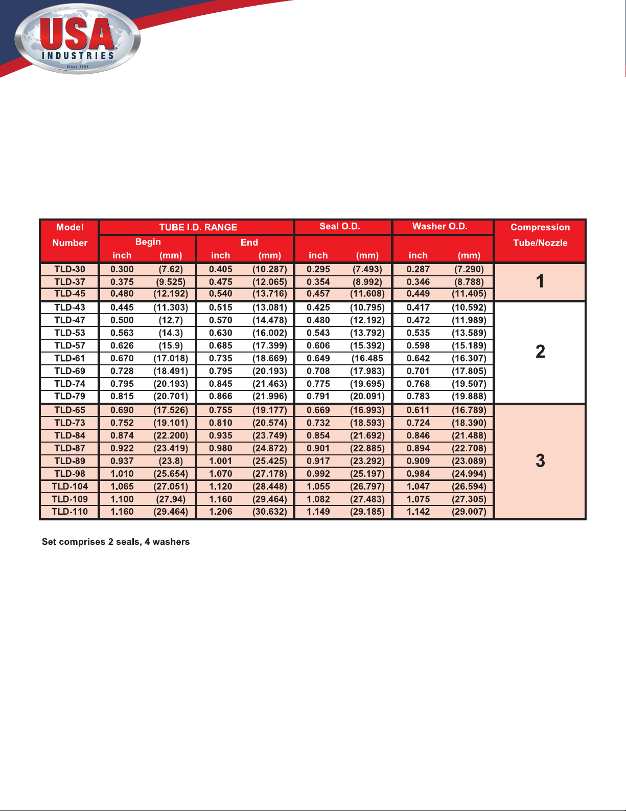
Make sure the test guns have the correct size replacement seal and washer sets and that both are
the correct size for the tubes being tested. Using seals that are too small can cause advanced seal
wear, test gun to stick in tube, or rapid ejection of the test gun from the inside of the tube. Seals
and washers outside diameters are considered correct if nominally 0.02”-0.06” (0.5mm-1.5 mm)
smaller than the tube’s inside diameter.
⚠
Replacement seals for the TLD 2500 Gun can be manufactured for any tube ID from 0.28”-1.23”
(7.1 mm-31.3mm). For tube inside diameters larger than 1.23” contact USA Industries at 1-800-
456-8721.
⚠
The procedure for replacing the seal and washer sets is further explained on page 4.
2. Testing Procedure
1. Never activate the TLD 2500 when inserted into a tube if the seal washers have to be forcefully
pushed to the inside of the tube. Correctly size the seals and washer sets before use. Failure to
do so can result in a stuck gun and/or damaged parts.
2. The TLD 2500 Guns are comprised of a pair, an Air Injection Gun and a Plugging Gun. The Air
Injection Gun is visibly dierent in that it contains an air control valve and a bleed valve. The
Plugging Gun is a companion gun to the Air Injection Gun and will not function without the
injection gun being present.
3. Ax air hose with air supply to Air Injection Gun.
4. USA Industries’ TLD 2500 Test Guns function on air supplies from 40-125 psi (2.7-8.6 Bar) with
a minimum of 5 cubic feet per minute (CFM). These limitations vary due other to pneumatic
tools and units that maybe online within your plant environment. If testing inside diameter tube
dimensions range from 0.28”-0.48” (7.1MM-12.3 mm) a regulator assembly must be attached
and the operating pressures must be kept within 40-60 psi. When installing the regulator
assembly the arrow should be pointed towards the gun and t onto an air hose attached to the
regulator input.

TLD-2500 OPERATING INSTRUCTION MANUAL www.USAIndustries.com | (713) 941-3797
©2022, USA Industries
M-OM-TLD2500-1.1
TLD-2500 TUBE TESTING GUNS
OPERATING INSTRUCTIONS
5. Insert the Air Injection Gun into one tube end and the Plugging Gun on the opposite end of
the tube being tested. Apply enough pressure to seat the plastic washer (Fig. 1 & Fig. 2 Item 4)
rmly against the end of the tube. Maintain this pressure throughout the remainder of the test.
6. Aer ensuring the Plugging Gun operator is ready, actuate the air control valve on the Injection
Gun and hold until the pressure gauge reading is steady.
7. Release the button on the air control valve. It will automatically return to the closed position
isolating the tube being tested. The tube is now under pressure.
8. Both Injection Gun and Plugging Gun operators should monitor their respective pressure
gauges. Any decreasing pressure observed on the gauges will be indicative of a tube leak. Press
the bleed valve on the Injection Gun to reduce the air pressure in the tube and reset the air
cylinder seals. If a leak has been indicated, repeat step 11 to insure leak was not caused by a
faulty seal to the tube.
9. Remove the Test Guns and relocate to the next tube. Identify each leaking tube for repair with a
mark. While actual testing time is approximately 5-10 seconds per tube, this process time may
vary depending on verication of a tube leak or amount of time used to create stable applied air
pressure.
10. Repeat the previous steps explained here for subsequent tube leak inspection.
3. Installing Replacement Seals:
1. Replacement seals for the TLD 2500 Guns are furnished with matched size washers. All seals
and washers should be replaced on both guns at the same time.
2. Remove the lock nut from the end of the support sha tube and place it to the side.
3. Remove the seal and washer set from the support sha tube and dispose of if worn. Estimated
number of operations per seal and washer set before replacement is approximately 100-500 tubes
depending on conditions and operator.
4. Wipe down sha and install replacement seal and washer on same sha. If the dimensions have
changed, you may be required to replace the support sha tube.
5. When replacing the lock nut (Fig. 1 & Fig. 2 Item 1) on the support sha tube hand tighten.
Do not use a wrench or other mechanical tool. A small gap between the lock nut and the seal
washer is typical. The air cylinder stroke distance will compensate for that space.

TLD-2500 OPERATING INSTRUCTION MANUAL www.USAIndustries.com | (713) 941-3797
©2022, USA Industries
M-OM-TLD2500-1.1
TLD-2500 TUBE TESTING GUNS
OPERATING INSTRUCTIONS
4. Replacing the Sha Support Tube Assembly:
The TLD Test Guns are shipped from the factory with three sets of seal stems (Fig. 1 & Fig. 2
Item 3) tube assemblies. Tube test inside diameters (ID) are:
Stem I - .28” - .48” (7.1 mm – 12.3 mm)
Stem II - .49” - .83” (12.4 mm – 21.2 mm)
Stem III - .84” - 1.23” (21.3 mm – 31.3 mm)
1. Remove all seal and washer sets as described in “Installing Replacement Seals” on page 3.
2. Using an open ended wrench on the wrench ats machined on the actuating piston (Fig. 1
& Fig. 2 Item 5) and a pipe wrench on the seal stem (Fig. 1 & Fig. 2 Item 3), loosen the tube
from the piston inside the cylinder in a counter clockwise manner.
3. Determine the correct size seal stem that is required for the tube ID being tested. All three
seal stems are the same dimension at the cylinder base to t into the piston. Use PTFE
tape or similar product to lubricate and seal threads. Do not over tighten seal stem when
reinstalling.
4. Inspect the seal stem for any scars le from disassembly or reassembly phases. File or sand
smooth if any irregularities exist.
5. Reinstall seal and washer sets per previously outlined procedure in “Installing Replacement
Seals” on page 3.
Warning! Other Replacement Parts/Repairs
UNDER NO CIRCUMSTANCES SHOULD AN ATTEMPT BE MADE TO
SERVICE THE AIR CYLINDERS. ANY ATTEMPT TO PERFORM SERVICE ON
CYLINDERS MAY VOID ANY AND ALL REMAINING WARRANTIES, IMPLIED
OR OTHERWISE STATED!

TLD-2500 OPERATING INSTRUCTION MANUAL www.USAIndustries.com | (713) 941-3797
©2022, USA Industries
M-OM-TLD2500-1.1
TLD-2500
SIZING CHART
Table of contents
Popular Test Equipment manuals by other brands

Tenma
Tenma 72-9966 quick start guide

Agilent Technologies
Agilent Technologies J-BERT N4903A Getting started

Clas Ohlson
Clas Ohlson UNI-T UT18C instruction manual

Safire
Safire SF-TESTER-ARM-5N1-4K instruction manual

ELMTEC
ELMTEC EC 25 operation instruction

Koehler
Koehler K501 Series Operation and instruction manual