SuperSail Marine Alarm User manual

Installation Manual
Page 1of 8
Installation Manual
SuperSail
Marine Alarm
Marine Alarm Wireless

Installation Manual
Page 2of 8
Table of Contents
1CONTENTS OF THE PACKAGE ...............................................................................................3
2INSTALLATION ...........................................................................................................................4
2.1 PLACEMENT...............................................................................................................................4
2.2 ENERGY CONSUMPTION.............................................................................................................4
2.3 12V CONNECTION .....................................................................................................................4
2.4 DIRECT CONNECTION.................................................................................................................5
2.4.1 Connection with SuperSail Fuse Box ...............................................................................5
2.5 CONNECTING WITH SUPERSAIL CONNECTION BOX....................................................................5
2.6 OUTBOARD MOTOR ALARM.......................................................................................................6
2.7 CABLE CONNECTED WATER SENSOR.........................................................................................6
2.8 WIRELESS WATER SENSOR .......................................................................................................6
2.9 WIRELESS MOTION SENSOR ......................................................................................................6
2.10 WIRELESS DOOR SENSOR..........................................................................................................6
2.11 WIRELESS REMOTE CONTROL...................................................................................................6
2.12 MAINTENANCE..........................................................................................................................6
2.13 TECHNICAL SPECIFICATIONS .....................................................................................................7
2.14 SAFE DISPOSAL .........................................................................................................................7
3SERVICE ........................................................................................................................................8

Installation Manual
Page 3of 8
1 Contents of the package
The complete Supersail Marine Alarm basic package consists of the following:
- SuperSail Marine Alarm base (note the serial number of the unit)
- GPS antenna
- Mobile (GSM) antenna
- Quick guide
Add-ons:
- Alarm connection box for cable connection of e.g. 12V and external sensors. Contains
also fuse for protection.
- Fuse box for connection of 12V only.
- Cable connected water sensor
- Wireless water sensor (can only be connected to Marine Alarm Wireless)
- Wireless motion sensor (can only be connected to Marine Alarm Wireless)
- Wireless door sensor (can only be connected to Marine Alarm Wireless)
- Wireless remote control (can only be connected to Marine Alarm Wireless)
- Cable connected siren (can only be connected to Marine Alarm Wireless)

Installation Manual
Page 4of 8
2 Installation
SuperSail Marine Alarm is delivered in a box containing the Alarm unit with associated
antennas and cables.
The Alarm unit must be connected to 12V external power supply and additional different
alarm sensors can be connected.
Keep the packaging in case the Alarm unit has to be sent.
2.1 Placement
The Alarm unit is placed indoor in the boat as high up as possible to get the optimal signal for
the GSM antenna to and from the mobile transmitter mas ashore.
The Alarm unit is mounted vertical with the GSM antenna pointing upwards.
The GPS antenna is placed horizontal with the text upwards to be able to receive the optimal
signal from the GPS satellites.
None of the antennas must be placed right under metal, since this will reduce the signal
strength significantly. Wood, plastic, glass, glass fiber and similar non-conducting materials
does not have any significant influence on the signals.
The GPS antenna is magnetic and can with advantage be placed on top of a metal plate or be
glued underneath another surface. The GPS text on the antenna has to turn upwards towards
the satellites for the best signal.
If the GPS antenna is not placed correct there will be a risk that it can receive reflecting
signals from the satellites from time to time and report a false alarm.
The GPS antenna is mounted with the black side (refer to the picture below) turning upwards
towards the satellites.
2.2 Energy consumption
In energy mode the Alarm unit uses: 0.6 mA
During operation the Alarm unit uses: 75 mA
During charging the Alarm unit uses: 500mA
The energy consumption during charging is limited in the unit and will never exceed the
specified, but can be lower than specified, since the charging circuit is intelligent and fit the
charging as required.
The charging stops automatically if the temperature of the Alarm unit exceeds 50 degrees
Celsius.
2.3 12V Connection
The Alarm unit is connected to 12V power supply on the primary side of the boats main
switch, to ensure that there is always power on the Alarm unit when the boat is shut down and
left.

Installation Manual
Page 5of 8
This is a precondition for the Alarm unit to function as secure and insurance approved
surveillance of the boat.
2.4 Direct connection
In the below table the connection of the different cables connected to the Alarm unit is shown.
The cables should be connected with pull relief to ensure that the movements of the boat over
time do not make the wires lose their connection.
Cable color
Connects to
Grey
No connection
Orange
No connection
Yellow
No connection
Red
Power +12V
Black
Power GND
Green
Activation signal from Input #1 (+12V)
Purple
Activation signal from Input #2 (+12V) –only
available for Marine Alarm Wireless
Light blue
Output #1 activation (+12V) –only available
for Marine Alarm Wireless
Blue
Output #2 activation (+12V) –only available
for Marine Alarm Wireless
White
Output/Input GND
2.4.1 Connection with SuperSail Fuse Box
Since the connection of the alarm system happens on the primary side, the power supply of
the Alarm unit must be secured by a 2,5A(T) fuse.
SuperSail Fuse box contains both fuse and connection for 12V battery.
+12V connects to the terminal marked with 12V and 0V to the terminal marked with GND.
Red cable from the Alarm unit connects to the terminal marked with TRK. Black cable from
the Alarm unit connects to the terminal marked with GND.
2.5 Connecting with SuperSail Connection box
Refer to Installation manual Connection box, found here: www.super-sail.dk/app-support

Installation Manual
Page 6of 8
2.6 Outboard motor Alarm
If the surveillance of the outboard motor is required a ground wire can be mounted from the
motor through wire bundle from the motor. If the wire bundle is cut for instance when theft is
happening the alarm will register this and the alarm unit sends an alarm message and will
turn on the siren.
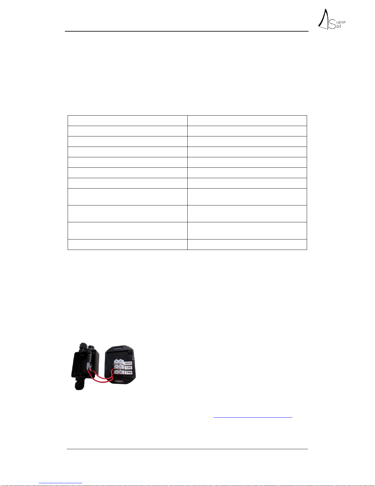
Since the input of the alarm detects alarms by enabling +12V at the input, a 1KOhm pull-up
resistor should be installed between the input and +12V. The ground wire from the outboard
motor connects to the input of the alarm. As long as the ground wire from the outboard motor
is intact 0V will be registered on the input to the alarm, but if ground wire is removed the pull-
up resistor will ensure that +12V is registered at the input and thus an alarm is activated.
If SuperSail Connection box is used the 1KOhm pull-up resistor is supplied within the box and
is connected as shown in the Installation Manual for the Connection box.
2.7 Cable connected Water Sensor
If the boat is equipped with automatic bilge pump the output from the float switch can be
connected to for instance Input1 in the Alarm box. Since the bilge pump uses quite some
power and is supplied through the float switch, a relay or other current limiter should be
installed before connecting to the Alarm box.
As an alternative a separate SuperSail Float switch is connection.
Refer to Installation manual Float switch, found here: www.super-sail.dk/app-support
2.8 Wireless Water Sensor
Refer to Installation manual Wireless Water sensor, found here: www.super-sail.dk/app-
support
2.9 Wireless Motion Sensor
Refer to Installation manual Wireless Motion sensor, found here: www.super-sail.dk/app-
support
2.10 Wireless Door Sensor
Refer to Installation manual Wireless Door sensor, found here: www.super-sail.dk/app-
support
2.11 Wireless Remote Control
Refer to Installation manual Wireless Remote control, found here: www.super-sail.dk/app-
support
2.12 Maintenance
The Marine Alarm system is maintenance free. Repairs should be carried out at an authorized
service center.
Cleaning can be carried out with a soft cloth wrenched in lukewarm water
Cleaning detergent containing solvent can harm the unit.

Installation Manual
Page 7of 8
2.13 Technical Specifications
Power supply 8-36V DC
Internal backup battery 1000 mAh Lithium
Power use during operation 75 mA ex. possible use from external units connected to
digital outputs
Power use energy mode 0.6 mA
Power use while charging 500 mA
Digital outputs +12V, max. 750 mA
Digital inputs +12V
Operational temperature -25 to +55 degrees Celsius
Charging temperature -10 to +45 degrees Celsius (protection of battery)
Humidity 5-90% non-condensing
Weight 250 g
Protection IP66
Size 92 x 30 x 58 mm (BxHxD)
Approvals EN-61000-6-3;2001 Emission
EN-61000-6-2;2001 Immunity
Changes may apply.
2.14 Safe Disposal
Should not be disposed as domestic waste.
Electronic equipment should be disposed according to the local regulations
for electronic and electronically equipment.

Installation Manual
Page 8of 8
3 Service
The Alarm system is on the front equipped with 3 LED.
LED 1 and LED 2 is solely for service purpose and is used in connection with troubleshooting
on the unit.
LED 3 can with advantage be used to verify the GPS signal after installation.
LED 1:
Pattern
Description
Fastest flash - green
The unit is initializing during startup
Fast flash –green or yellow
The unit is stopped
500 ms on / 500 ms off green or yellow
The unit is running normally
1,5 s on / 0,5 s off green or yellow
The unit is running normally and the battery
is charging
Fast flash red or yellow
The unit is stopped because of an error
Changing fast/slow red or yellow
The unit has lost its firmware
75 ms on / 925 ms off
The unit is running with decreased speed
LED 2:
Pattern
Description
Off
The GSM communication is off
600 ms on / 600 ms off
Initializing the GSM connection
75 ms on / 3 s off
Connected to the GSM no activity
75 ms on / 75 ms off
GPRS session on-going
Fast flash
GPRS data transfer on-going
10 ms on / 8 s off
The unit is in energy saving mode
LED 3:
Pattern
Description
Green
The GPS signal is ok. The GPS is only ON
when the unit is active
Red
The GPS signal is missing or low receiver
quality
Other manuals for Marine Alarm
3
This manual suits for next models
1
Table of contents
Other SuperSail Security System manuals
Popular Security System manuals by other brands

Eldes
Eldes ESIM364 user manual

ADT
ADT Commercial Fire & Burglary Alarm System FOCUS 200... Installation and setup guide

Firex
Firex FADCM manual

Ocean Signal
Ocean Signal rescureME MOB1 user manual

Geoquip
Geoquip Commander Engineering and installation manual

urmet domus
urmet domus Bitron Home 902010/29 Quick start manual