Superwince EX1 User manual

OWNER’S MANUAL
INSTALLATION • OPERATION • MAINTENANCE
SAFETY PRECAUTIONS • REPAIR PARTS
READ AND UNDERSTAND THIS MANUAL
BEFORE INSTALLATION AND OPERATION
OF YOUR SUPERWINCH PRODUCT.
90-10439 Rev D– 5/15/98
Superwinch, Inc. Superwinch, Ltd.
Winch Drive Abbey Rise, Whitchurch Road
Putnam, CT 06260 Tavistock, Devon PL 19 9DR
U.S.A. England
Tel. (860) 928-7787 Tel. (1822) 614101
Fax (860) 928-1143 Fax (1822) 615204
MODEL EX1
12 Volt DC Electric Winch
Part No. 1110

2
Thank you very much for purchasing a Superwinch product. We hope and
expect that you will be pleased with the performance and reliability of this
unit. If you are not, for any reason, please contact our Customer Service
Department: (860) 928-7787 USA; (1822) 614101 England.
When requesting information or ordering replacement parts; always give the
following information:
1. Winch Part Number (1110)
2. Part Number (found in Replacement Parts List section)
3. Part Description
It is extremely important that you read and understand this Owner’s Manual
prior to installing and using your winch. Pay particular attention to “General
Safety Information” and be sure that anyone else who might use your winch
also studies this section.
Pay particular attention to the caution notes preceded
with this symbol. The notes contain advice for your
protection.
Description Quantity
Winch assembly with wire rope and hook 1
Switch and harness assembly with two 5' long 10-gauge wires 1
Handsaver 1
Circuit breaker assembly 1
3/8 x 1-1/2 grade 5 bolts, nuts, flat washers and lock washers 2 ea.
Cable ties 5
INTRODUCTION
UNPACKING: This carton contains the following items. Please unpack care-
fully. Read instructions before beginning.
PERFORMANCE
Motor
Load Speed Current
lbs kg ft/min m/min Amps
0 0 20 6.1 20
1,000 454 12 3.66 90
Working Load . . . . . 1,000 lbs. (454 kg)
Stall Load . . . . . . . . . 1,350 lbs. (612 kg)
Wire Rope . . . . . . . . . . 5/32 x 25 ft.
Voltage . . . . . . . . . . . . . 12 Volt DC
Motor . . . . . . . . . . . . . . . . . . .6 hp
Gear Ratio . . . . . . . . . . . . . . . 123:1
Weight . . . . . . . . . . 15 lbs. (6.8 kg)
SPECIFICATIONS
Slope* 10% (6º) 20% (11º) 30% (17º) 100% (45º)
Lbs.**
kg** 5,000
2268 3,400
1542 2,600
1179 1,200
544
Ratings assume a 10% coefficient of friction.
* A 10% slope is a rise of one foot in ten feet. Slope in approximate degrees is also shown above.
** All loads shown are for single-line operation (see Figure 1). Double-line operation with optional
pulley block (p/n 2227) approximately doubles capacity of winch (see Figure 1).
LOAD CAPACITY**

Your new Superwinch is a powerful
machine. Treat it with respect, use it
with caution and always follow
these safety guidelines.
1. The EX1 winch is rated at 1,000
lbs. (single-line) capacity. DO NOT
OVERLOAD. DO NOT ATTEMPT
PROLONGED PULLS AT HEAVY
LOADS. DO NOT MAINTAIN
POWER TO THE WINCH IF THE
MOTOR STALLS. Overloads can
damage the winch and/or the
wire rope and create unsafe
operating conditions. FOR
HEAVY LOADS, WE RECOM-
MEND THE USE OF THE
OPTIONAL PULLEY BLOCK AND
HOOK ASSEMBLY (PART NO.
2227) TO DOUBLE-LINE THE
WIRE ROPE (Figure 1). This
reduces the load on the winch
and the strain on the wire rope
by approximately 50%.
2. AFTER READING AND UNDER-
STANDING THIS MANUAL,
LEARN TO USE YOUR WINCH.
Practice using it so you will be
familiar with it when the need
arises. Periodically check the
winch installation to assure that
all bolts are tight.
3. DO NOT “move
”
your vehicle to
assist the winch in pulling a load.
The combination of the winch
and vehicle pulling together
could overload the wire rope and
the winch itself.
4. KEEP WINCHING AREA CLEAR.
Do not allow people to remain in
the area during winching opera-
tions. Do not step over a taut
wire rope or allow anyone else to
do so. Do not stand between the
winch and load.
5. INSPECT WIRE ROPE AND
EQUIPMENT FREQUENTLY. A
FRAYED WIRE ROPE WITH BRO-
KEN STRANDS SHOULD BE
REPLACED IMMEDIATELY.
Always replace wire rope
with the manufacturer’s iden-
tical replacement part, (see
Replacement Parts List). Never
replace the wire rope with any
kind of rope other than the type
and size specified in the Wire
Rope section of this manual.
6. USE HEAVY LEATHER GLOVES
when handling wire rope. DO
NOT LET WIRE ROPE SLIDE
THROUGH YOUR HANDS. A bro-
ken strand could seriously injure
your hands.
7. KEEP CLEAR OF THE WINCH,
WIRE ROPE, AND HOOK WHEN
OPERATING WINCH. NEVER put
your fingers through the hook
when reeling in the last few feet
of line. If your finger should
become trapped in the hook, you
could lose your finger. Use the
HAND SAVER BAR (Figure 2) to
guide the hook within the last
few feet. Never guide a wire rope
on or off the drum with your hand.
3
GENERAL SAFETY
INFORMATION
Figure 2
Single Line Double Line
Figure 1

4
8. NEVER HOOK THE WIRE ROPE
BACK ONTO ITSELF. Use a nylon
sling (Superwinch Part No. 1509).
Hooking the wire rope onto itself
can damage the rope (Figure 3).
9. It is a good idea to lay a heavy
blanket or jacket over the wire
rope near the hook end when
pulling heavy loads (Figure 4). If
a wire rope failure should occur,
the cloth will act as a damper
and help prevent the rope from
whipping. Raise the hood of the
vehicle for added safety.
10.NEVER USE YOUR WINCH FOR
LIFTING OR MOVING PEOPLE.
The winch is not designed nor
intended for use in lifting or
moving people.
11.Your winch is not designed or
intended for overhead hoisting
operations.
12.DO NOT ATTEMPT PULLS
FROM ANGLES WITHOUT
USING OPTIONAL FAIRLEAD,
P/N 1507 OR 1560, as damage
to winch and wire rope may result.
13.AVOID CONTINUOUS PULLS
FROM EXTREME ANGLES as
this will cause the wire rope to
pile up at one end of the drum
(Figure 5). This can jam the wire
rope in the winch, causing dam-
age to the wire rope or winch
itself.
14.Always operate winch with an
unobstructed view of the winch-
ing operation.
15.IT IS RECOMMENDED THAT A
FAIRLEAD BE USED to guide
the wire rope onto the winch.
Two types of fairleads are
offered: the Hawse Fairlead,
Part No. 1507, and the Roller
Fairlead, Part No. 1560.
16.DO NOT OPERATE WINCH
WHEN UNDER THE INFLUENCE
OF DRUGS, ALCOHOL OR
MEDICATION.
17.ALWAYS REMOVE THE
SWITCH BEFORE WORKING IN
OR AROUND THE WIRE ROPE,
FAIRLEAD, OR WINCH DRUM
(THE DANGER ZONE) so that
the winch cannot be turned on
accidentally.
18.NEVER WORK ON OR
AROUND THE FAIRLEAD OR
WINCH DRUM, WHEN WINCH
IS UNDER LOAD.
19.When using your winch to move
a load, place the vehicle trans-
mission in neutral, set vehicle
parking brake, chock all wheels,
and keep the engine running.
GENERAL SAFETY
INFORMATION
(CONT.)
Wrong Right Right Wrong
Figure 5
Figure 3
Figure 4

20.DO NOT USE THE WINCH TO
HOLD LOADS IN PLACE.
Use other means of securing
loads such as tie down straps.
Superwinch offers a wide variety
of tie down straps. Contact your
local Superwinch dealer.
21.USE ONLY FACTORY
APPROVED SWITCHES,
REMOTE CONTROLS, AND
ACCESSORIES. Use of non-fac-
tory approved components may
cause injury or property damage
and could void your warranty.
22.DO NOT MACHINE OR WELD
ANY PART OF THE WINCH.
Such alterations may weaken
the structural integrity of the
winch and could void your warranty.
23.Maintain 5 turns of wire rope
around wire rope drum to pre-
vent the wire rope from pulling
off under load.
24.NEVER INSTALL WINCH IN
SUCH A WAY THAT THE
WARNING AND INSTRUCTION
LABELS ARE OBSCURED.
Someone who had not read this
manual may need to see them
to understand the proper opera-
tion of the winch. ALWAYS
CHECK FOR CORRECT DIREC-
TION OF ROTATION BEFORE
USING WINCH. The winch must
be properly wired to ensure cor-
rect direction of rotation.
25.When moving a load, slowly
take up the wire rope slack until
it becomes taut. Stop, recheck
all winching connections. Be
sure the hook is properly seated.
If a nylon sling is used, check the
attachment to the load.
26.Always install winch in such a
way that the operator will be
standing with a comfortable
posture, with unobstructed
access to, and a clear view of the
winch, its labels, and its controls.
TOOLS NEEDED FOR MOUNTING
AND WIRING
Open End Wrenches – 9/16", (2), or
small adjustable wrenches, wire
strippers, or cutters, terminal
crimpers (pliers), torque wrench, Pair
3/8" bolts and nuts, four flat and
two lock washers.
MOUNTING
The mounting location for the
winch must be capable of handling
the loads of the job you intend the
winch to do. Suggested locations
are: a flat front or rear bumper of a
vehicle, on a pickup truck bed or the
winch stand on a trailer.
The winch can be mounted in a hor-
izontal or vertical position (Figure
6). Do not mount the winch where
there would be the possibil-
ity of it being submerged in water.
The winch is weather resistant but
not waterproof.
Superwinch mounting (fitting) kits
are available for most popular vehi-
cles. If you can’t obtain a kit locally,
contact Superwinch at the address
listed in this manual for the name of
a Superwinch dealer near you.
5
GENERAL SAFETY
INFORMATION
(CONT.)
INSTALLATION
Horizontal
Vertical
Figure 6

6
MOUNTING (CONT.)
Drill two 7/16" (12mm) diameter
holes with center lines exactly
3-11/16" (93.66mm) apart (Figure 7)
in the support chosen for the
winch. Attach the winch to the sup-
port with two (2) 3/8-16 Hex Head
Bolts. Be sure the hardware is
assembled as shown. Tighten the
hardware to 35 lb. ft. torque.
ELECTRICAL INSTALLATION
This winch operates on standard
automotive 12-volt Direct Current.
Do not
connect winch
to 110 Volt house current. Motor
damage or fatal shock may occur.
Automobile
batteries con-
tain gasses which are flammable and
explosive. Wear eye protection dur-
ing installation and remove all metal
jewelry. Do not lean over the bat-
tery while making connections.
The red wire from the switch is
connected to the circuit protector
terminal using the hardware pro-
vided. The other end of the circuit
protector is connected to the bat-
tery positive terminal. The black
wire from the switch is connected
to the battery negative terminal
(Figure 8). Be sure connections are
clean and tight. Do not connect the
switch or wiring to any other power
source in the vehicle.
Starting at the winch, feed the
wires into the engine compartment.
If possible, use the routing and sup-
port for the existing wiring.
If it is necessary to drill holes, to
feed the wires, be sure the wires
are protected from damage by
using a grommet (Figure 9). Use
cable ties to secure wires along the
route.
When you make the ground con-
nection, be sure to scrape off any
dirt from the bolt that would pre-
vent a good connection.
Note: If the winch is mounted at
the rear of the vehicle, a special
wiring kit (P/N 1520) is available
from Superwinch.
When extending the lead wires for
rear vehicle mount, always use 8
gauge wire or heavier to extend the
existing wires to the battery.
Figure 7
Bolt
Flat Washer
Support
Flat Washer
Lock Washer
Nut
Figure 8
Circuit
Protector
Chassis
Ground Red
Black
Figure 9
Grommet
Tie Strap
Be Prepared

7
If connection to the battery positive
terminal is not possible because of
the terminal design, connect the
circuit protector to the starter
solenoid “hot” side. Determine the
“hot” side by tracing the battery
cable to the solenoid connection.
Connect the red supply wire to the
same terminal to which the battery
cable is connected (Figure 10).
Note: Special adapters are available
from your local Auto Parts Dealers
for making connections to Side Post
Batteries.
The switch and motor end are
designed so the switch will mount
properly only when installed as
shown in Figure 11. Do not attempt
to install the switch in the opposite
direction. If the switch is installed
incorrectly and electrical contact
made, the winch will run in a direc-
tion opposite that is indicated on
the product label resulting in possi-
ble operator injury.
Secure the switch to the motor by
tightening the round thumb screw
on the outside of the switch (Figure
12). The screw threads into the
tapped hole between the brass
motor contact (Figure 11). Do not
use pliers or over-tighten the thumb
screw.
After the switch is in place, remove
excess slack from the wiring harness
in the vehicle by doubling over
slack areas and tying securely. Do
not leave any dangling or loose
wiring.
Circuit
Protector
From Switch
Figure 10
Battery
Cable
Circuit
Protector
Red
Solenoid
Figure 11
Switch
Wires
Figure 12

8
SWITCH OPERATION
When the switch springs back to the
“OFF” position, an electrical shunt pro-
vides dynamic braking action which
prevents the winch from coasting
(Figure 13). THIS BRAKING ACTION IS
NOT A LOAD HOLDING DEVICE.
When the switch is centered in the
“OFF” position, the shunt reduces the
action of a load backdriving the winch.
However, a load can cause the winch
to creep. With the switch removed
from the winch, there is a greater ten-
dency for a load to backdrive the
winch.
The winch is
not designed
as a load holding device.
The switch should be removed from
the winch when unattended to pre-
vent unauthorized operation. A
Quickconnect (Superwinch P/N 1551) is
also available as an accessory to disarm
the winch. Because the winch will not
hold a load, in trailing or load holding
applications, tie down ropes or straps
must be used to secure loads.
Remote operation of the switch
(Figure 14) can be achieved by tying
one end of a cord through each “ear”
of the switch.
Periodically check tightness of the
mounting bolts and electrical connec-
tions. Remove any dirt or corrosion
that may have accumulated on the
electrical connections.
LUBRICATION
Your new winch has lifetime lubrica-
tion. There will be some grease leaking
out of the winch, especially during the
first few operations. This is normal and
it is not necessary to grease or oil any
part of the winch at any time.
WIRE ROPE
A part of your winch that will require
periodic attention and eventual
replacement is the wire rope. Inspect
the wire rope for wear frequently. If
fraying exists, replace the wire rope at
once. Your winch uses 5/32" diameter
galvanized aircraft type 7 x 19 wire
rope that is 25 feet long (2,800 lb.
breaking strength). Always replace the
wire rope with Superwinch replace-
ment wire rope, P/N 1535 (see
Replacement Parts List).
OPERATION
Figure 13
Off Rope In
Rope Out
MAINTENANCE
Figure 14

9
If the winch motor labors and then
stops, the load is too great.
Evidence of this will be a motor
almost too hot to touch. Repeated
occurrence of this condition indi-
cates that the load exerted on your
winch is beyond its capacity and
may burn out the winch motor. Use
of the accessory pulley block, P/N
2227, will increase the winch‘s
capacity.
MOTOR DOES NOT OPERATE
Follow these steps in order. Make
sure your vehicle engine is running
and then try operating your winch
after each step.
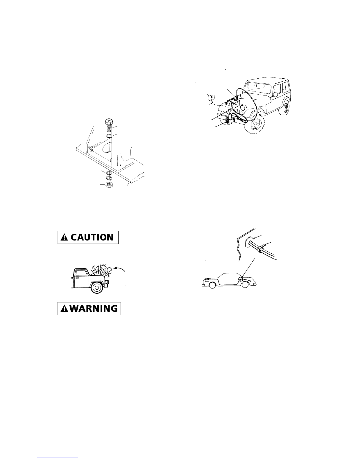
1. Remove switch, then replace it on
the motor, making certain that it
is aligned properly over brass
motor connectors and that thumb
screw is snug.
2. If motor does not operate, check
all electrical connections on bat-
tery and ground, making sure
that they are clean and tight.
3. Check the wiring harness to
determine if all insulation is
intact. Damaged insulation could
cause a short circuit.
TIPS F0R EXTENDING THE LIFE OF
YOUR WINCH
1. KEEP A TIGHTLY AND EVENLY
WOUND WIRE ROPE DRUM. Do
not allow the wire rope to
become loosely wound. A loosely-
wound drum allows a wire rope
under load to work its way down
into the layers of wire rope on
the drum. When this happens,
the wire rope may become
wedged within the body of the
windings, damaging the wire
rope. To prevent this problem,
keep the wire rope tightly and
evenly wound on the drum at all
times. During winching, periodi-
cally check to see that the wire
rope is winding on evenly. A
good practice is to rewind the
wire rope under tension after
each use. One way to do this is to
attach the hook to a stationary
object at the top of a small hill or
incline and winch your vehicle up
the incline.
2. DO NOT ALLOW MOTOR TO
OVERHEAT. Remember, the
winch is only for intermittent use.
During long or heavy pulls the
motor will get hot. The internal
parts will be hotter than the case.
To check the motor temperature,
stop winching and carefully touch
the motor. If the motor is uncom-
fortably warm, allow the motor
to cool before continuing. Keep
the engine running to recharge
the battery during this break.
3. USE A PULLEY BLOCK FOR
HEAVY LOADS. To maximize
winch and wire rope life, use a
pulley block, P/N 2227, to double-
line heavier loads.
4. The pull required to start a load
moving is often much greater
than the pull required to keep it
moving. AVOID FREQUENT
STOPPING AND STARTING
DURING A PULL.
TROUBLE SHOOTING
Figure 15

10
5. PREVENT KINKS BEFORE THEY
OCCUR.
6. EQUIPPING THE WINCH WITH A
ROLLER FAIRLEAD, P/N 1560,
Figure 17, will substantially
reduce wear on the wire rope
during angle pulls. The rollers
eliminate heavy rubbing and
abrasion to the wire rope.
a
b
c
a.This is the start of a kink. At this time,
the wire rope should be straightened.
b.The wire rope was pulled and loop has
tightened into a kink. Wire rope is now
permanently damaged and must be
replaced.
c. The result of kinking is that each
strand pulls a different amount causing
strands under greatest tension to break
and reduce load capacity of the wire
rope. The wire rope must be replaced.
Figure 17
Figure 16
10

11
REPLACEMENT
PARTS LIST
1
18
16
236
545
789
11 12
13
14
15
10
1 Handsaver 89-32300 1
2 Rotating Gear Drum 90-32038 1
3 Perimeter Bearing 90-23137 1
4 Nylon Step Washer 90-12418 1
5 Carrier Bearing 90-23140 2
6 Planetary Gearing Assembly 90-23138 1
7 10-Tooth Sun Gear 90-22865 1
8 Flat Thrust Washer 90-23120-08 1
9 Stationary Ring Gear w/ Needle Bearing 90-12454 1
10 12 Volt Motor w/ Ring Gear
& Needle Bearing Primed 90-32084 1
11 Shim Washer 90-23120-05 AR
12 Bushing 90-12174 1
13 5/16" Socket Head Cap Screw 90-23056-02 2
14 Main Frame Base Plate 90-41019 1
15 Repair Switch Assembly w/ two 3 ft. leads (includes
two butt splices for connecting to old harness) 1519 1
16 5/32" x 25' Wire Rope & Hook Assembly 1535 1
17 12V Circuit Breaker Assembly (Not Shown) 90-22873-03 1
18 Rope Retainer 90-12419 1
19 7,000 lb. Pulley Block (Figure 15) 2227 —
20 Hawse Fairlead (Not Shown) 1507 —
21 Roller Fairlead (Figure 17) 1560 —
22 Quickconnect (Not Shown) 1551 —
AR denotes “As Required”
Reference
Number Description Part Number Qty

NOTES
12

NOTES
13

14
NOTES

15
WARRANTY REPAIR CENTERS
USA
Superwinch Inc.
Winch Drive
Putnam, CT 06260
860-928-7787
C & A Equipment
W. 6209 Hwy. 33
P.O. Box 387
Pardeeville, WI 53954
608-429-9353
Electric Motor Repair
2010 North 4th Street
Minneapolis, MN 55411
612-588-4693
Marine Electric
9804 James Circle
Bloomington, MN 55431
612-881-0077
Appliance Hospital
4530 Beechnut
Houston, TX 77096
713-668-6705
J & L Equipment
12346 S.E. Raymond
Portland, OR 97236
503-760-6117
Zorko’s Alternator Service
30 Wells Road
Home, PA 15747
800-468-5055
Electric Motors of Iowa
50 Commercial Court
Iowa City, IA 52246
319-354-4040
CANADA
Les Equipment Twin
10401 Parkway Blvd.
Ville D’Anjou, Quebec H1J 1R4
514-353-1190
DJT Automotive
105 Riviera Drive, Unit 11
Markham, Ontario L3R 5M1
416-496-0631
Buffalo Industries
251 Princess Street
Winnipeg, Manitoba R3B 1M1
204-942-1951
Saskatoon All Terrain
421 Dickey Cresent Road
Saskatoon, Saskatchewan S7L 5P2
306-394-2155
Air Electric Service
6739 76th Avenue
Edmonton, Alberta T6B 0A9
403-465-0906
H.E. Brown Supply co., Inc.
150 MacIntyre Street East
P.O. Box 538
North Bay, Ontario P1B 8J3
705-472-0400
Argo Dist.
9431 63rd Avenue
Edmonton, Alberta T6B OG2
403-438-4443
UNITED KINGDOM
Superwinch, LTD
Abbey Rise, Whitchurch road
Tavistock, Devon PL19 9DR
(1822) 614101
WORLDWIDE
Contact your local Superwinch
Distributor or call Superwinch

VALID WORLDWIDE
LIMITED WARRANTY
Superwinch Inc. (“Seller”) warrants to the original buyer (“YOU”) all parts and components except
wire rope to be free of defects in materials and workmanship for a period of ONE (1) year from
provable date of purchase. Any Superwinch product which is defective will be repaired or replaced
without charge to you, upon compliance with these procedures. The warranties set forth herein
are exclusive and in lieu of all other warranties, whether oral or written, express or implied.
LIMITED WARRANTY PERFORMANCE PROCEDURE
Upon discovery of a defective Superwinch product, you shall mail to the Seller at his factory or to
any Factory Authorized Service Center written notice of such defect and mail, ship or otherwise
deliver the defective Superwinch, postage or shipping prepaid. Repairs or replacements by Seller
under this Limited Warranty will normally be accomplished within fifteen (15) business days after
receipt of the defective Superwinch. Seller or its Authorized Agents may make reasonable charges
for parts and labor for repairs not covered by this Limited Warranty.
WARRANTY AND REMEDY LIMITATIONS AND EXCLUSIONS
Repair and/or replacement of the defective Superwinch or component part thereof as provided
herein is the exclusive remedy for you. The following exclusions or limitations of warranties and
limitations of remedies shall be expressly applicable:
A. Express Warranties. Seller Warrants that the Superwinch is as described in the ”Superwinch
Owner’s Manual” provided herewith; no other express warranty is made in respect to the
Superwinch. If any model or sample was shown to you, such model or sample was used for illustra-
tive purposes only, and shall not be construed as a warranty that the Superwinch will conform to
the sample or model. SELLER MAKES NO EXPRESS WARRANTY WITH RESPECT TO THE WIRE ROPE
INCORPORATED IN THE PRODUCT.
B. Implied Warranty. The implied warranty of merchantability and all other implied warranties
shall only extend from the provable date of purchase for one (1) year. The wire rope is sold ”as is,”
without any implied warranties. Some states within the U.S.A. do not allow limitations on how
long an implied warranty lasts, so the above limitation may not apply to you.
C. Incidental and Consequential Damages. SUBJECT TO THE SELLER’S LIMITED WARRANTY OBLIGA-
TIONS SET FORTH HEREIN, SELLER SHALL NOT BE RESPONSIBLE FOR INCIDENTAL DAMAGES OF
ANY KIND, OR FOR CONSEQUENTIAL DAMAGES TO PROPERTY, LOSS OF PROFITS AND LOSS OF USE
WHICH MAY BE CAUSED BY ANY DEFECT IN, OR MALFUNCTION, OR FAILURE OF THE ENCLOSED
SUPERWINCH. SOME STATES WITHIN THE USA DO NOT ALLOW THE EXCLUSION OR LIMITATION OF
INCIDENTAL OR CONSEQUENTIAL DAMAGES, SO THE ABOVE LIMITATION OR EXCLUSION MAY
NOT APPLY TO YOU.
D. Condition of Warranty. Seller shall not be required to comply with its warranty duties provided
herein if the defect, malfunction, or failure of the Superwinch was caused by damage (not resulting
from defective or malfunctioning components) or unreasonable use by you. Unreasonable use shall
include, but not be limited to, the failure to provide reasonable and necessary maintenance or
installation or use of the Superwinch without compliance with the instructions contained in the
Superwinch Owner’s Manual, and subjecting the Superwinch to loads in excess of the load listed in
the Owner’s Manual for the particular model number. Seller’s liability under this warranty or for any
loss or damage to the Superwinch product shall not exceed the cost of correcting the defects in or
replacing the Superwinch product, and upon expiration of the warranty period, all such liability
shall terminate. The agents, dealers and employees of the Seller are not authorized to make modifi-
cations to this warranty, or additional warranties binding on the Seller. Accordingly, additional state-
ments, whether oral or written, do not constitute warranties and should not be relied upon.
LEGAL REMEDIES OF BUYER
This Limited Warranty gives you specific legal rights, and you may also have other rights which
may vary from state to state within the USA and from country to country. You also have implied
warranty rights. In the event of a problem with Limited Warranty service or performance, you may
be able to go to small claims court, a state court, or federal district court in the USA or to appro-
priate jurisdictions outside the USA.
INQUIRIES
Any inquiries regarding compliance with warranties provided herein may be addressed in writing
to: Superwinch Inc., Winch Drive, Putnam, CT 06260, USA or to: Superwinch Ltd., Abbey Rise,
Whitchurch Road, Tavistock, Devon PL 19 9DR, England.
LIMITED WARRANTY

90-10439 Rev D– 5/15/98
MANUAL DEL PROPIETARIO
INSTALACIÓN • OPERACIÓN • MANTENIMIENTO
PRECAUCIONES DE SEGURIDAD
PIEZAS DE REPUESTO
MODELO EX1
Cabrestantes eléctricos de
12 Volts
Nº de Pieza 1110
LEAY ENTIENDA ESTE MANUALANTES DE INSTA-
LAR Y OPERAR SU PRODUCTO SUPERWINCH.
Superwinch, Inc. Superwinch, Ltd.
Winch Drive Abbey Rise, Whitchurch Road
Putnam, CT 06260 Tavistock, Devon PL 19 9DR
E.U.A. Inglaterra
Tel. (860) 928-7787 Tel. (1822) 614101
Fax (860) 928-1143 Fax (1822) 615204

Gracias por comprar un producto Superwinch. Esperamos que esté satisfe-
cho con el rendimiento y confiabilidad de esta unidad. Si no lo está por
cualquier motivo, por favor comuníquese con nuestro Departamento de
Servicio al Cliente al: (860) 928-7787 en E.U.A.; (1822) 614101 en Inglaterra.
Cuando solicite información o piezas de refacción, siempre dé la siguiente
información:
1. Número de Pieza del Cabrestante (1110)
2. Número de Pieza (se encuentra en la lista de piezas de este manual)
3. Descripción de la Pieza
Es extremadamente importante que usted lea y entienda este Manual del
Propietario antes de instalar su cabrestante. Ponga particular atención a la
«Información General de Seguridad» y asegúrese que cualquier persona que
pueda operar el cabrestante también estudie esta sección.
Ponga particular atención a las notas de precaución pre-
cedidas de los símbolos mostrados aquí. Las notas con-
tienen consejos para su protección.
DESEMPACADO: Esta caja contiene los siguientes artículos. Por favor desem-
páquelos cuidadosamente. Lea las instrucciones antes de comenzar.
Descripción Cantidad
INTRODUCCIÓN
DESEMPEÑO
Corriente
Carga Velocidad del motor
lbs kg Ft/min m/min Amps
0 0 20 6.1 20
1,000 454 12 3.66 90
Carga de Tabajo. . 454 Kg. (1000 lb)
Carga de Pérdida . . . . . . . . . 612 kg
(1,350 lb)
Cable 4.0 mm (5/32") x 7.62 m (25')
Voltaje. . . . . . . . . . . . . . . . . 12 VCD
Motor . . . . . . . . . . . . . . . . . . . .6 HP
Relación de Engranes. . . . . . . 123:1
Peso . . . . . . . . . . . . . . 6.8 kg (15 lb)
ESPECIFICACIONES
Pendiente* 10% (6º) 20% (11º) 30% (17º) 100% (45º)
Lbs.**
kg** 5,000
2268 3,400
1542 2,600
1179 1,200
544
Las especificaciones asumen un 10% de coeficiente de fricción.
* Una pendiente de 10% es una elevación de 30.48 cm en 3.048 m (1' en 10'). Arriba también se muestra una
pendiente en grados aproximados.
** Todas las cargas mostradas son para operación de línea sencilla (vea la Figura 1). La operación de línea doble con
el bloque de poleas opcional (Nº/P 2227) duplica aproximadamente la capacidad del cabrestante (vea la
Figura 1).
CAPACIDAD DE CARGA RODANTE**
18
Conjunto de cabrestante con cable de alambre y gancho 1
Interruptor y conjunto de contacto con 1.52 m (5’)
de cable de calibre 10 1
Barra protectora para manos 1
Conjunto de cortacircuitos 1
tornillos de 3/8 x 1-1/2” grado 5, tuercas,
rondanas planas y de presión 2 de c/u
Cintas para atar cables 5

Su nuevo cabrestante Superwinch
es una máquina poderosa. Trátela
con respeto, úsela con precaución y
siga siempre estas normas de
seguridad.
1. El cabrestante EX1 está clasifica-
do a una capacidad (de línea
sencilla) de 454 kg. (1000 lb).
NO LO SOBRECARGUE. NO
INTENTE TIRAR DE CARGAS
PESADAS POR TIEMPO PROLON-
GADO. NO MANTENGA LA COR-
RIENTE AL CABRESTANTE SI EL
MOTOR ENTRA EN PÉRDIDA. Las
sobrecargas pueden dañar el
cabrestante y/o el cable de
alambre y crear condiciones
inseguras de operación. PARA
CARGAS PESADAS, USE UN
CONJUNTO DE BLOQUE DE
POLEAS Y GANCHO (Nº DE
PIEZA 2227) PARA DUPLICAR LA
LÍNEA DE CABLE DE ALAMBRE
(Figura 1). Esto reduce la carga
sobre el cabrestante y el esfuer-
zo del cable de alambre en un
50% aproximadamente.
2. APRENDA A USAR SU
CABRESTANTE DESPUÉS DE
LEER Y ENTENDER ESTE MANU-
AL. Practique su uso para que
esté familiarizado con su
operación cuando surja la
necesidad de usarlo. Revise per-
iódicamente la instalación del
cabrestante para asegurarse que
los tornillos estén apretados.
3. NO «mueva» su vehículo para
ayudar al cabrestante a tirar de
una carga. La combinación del
cabrestante y el vehículo al tirar
juntos puede sobrecargar el
cable de alambre y el
cabrestante mismo.
4. MANTENGA DESPEJADA EL
ÁREA DE CARGA. No permita
que la gente se quede en el
área durante la operación del
cabrestante. No salte sobre un
cable tenso ni permita que
nadie lo haga. No se pare entre
el cabrestante y la carga.
5. INSPECCIONE FRECUENTEMENTE
EL CABLE DE ALAMBRE Y EL
EQUIPO. UN CABLE DE ALAM-
BRE DESHILACHADO CON HILOS
ROTOS DEBE REEMPLAZARSE
INMEDIATAMENTE.
Siempre reemplace el cable de
alambre con la pieza de
repuesto idéntica del fabricante
(vea la Lista de Piezas de
Refacción). Nunca reemplace el
cable de alambre con ningún
tipo de cable que no sea el del
tipo o tamaño especificados en
la sección del Cable de Alambre
de este manual.
6. USE GUANTES DE CUERO PESA-
DO cuando maneje el cable de
alambre. NO DEJE QUE EL
CABLE DE ALAMBRE SE DESLICE
EN SUS MANOS. Una hebra rota
puede lesionar gravemente sus
manos.
7. MANTÉNGASE ALEJADO DEL
CABRESTANTE, DEL CABLE DE
ALAMBRE TENSO Y DEL GAN-
CHO CUANDO ESTÉ OPERANDO
EL CABRESTANTE. NUNCA
atraviese el gancho con los
dedos cuando enrolle los últi-
mos centímetros de línea. Si su
dedo queda atrapado en el gan-
cho, podría perderlo.
19
Figura 1 Línea doble
Figura 2
INFORMACIÓN GENERAL
DE SEGURIDAD
Línea sencilla

Use la BARRA PROTECTORA
PARA MANOS (Figura 2) inclui-
da con el cabrestante para
guiar el gancho los últimos
centímetros. Nunca guíe el
cable de alambre con las
manos hacia el tambor o hacia
afuera.
8. NUNCA ENGANCHE EL CABLE
DE ALAMBRE SOBRE SÍ
MISMO. Use una eslinga de
nilón (Nº de Pieza Superwinch
1509). Enganchar el cable
sobre sí mismo puede dañarlo
(Figura 3).
9. Es una buena idea poner una
frazada pesada o una chamar-
ra sobre el cable de alambre
cerca del extremo del gancho
cuando tire de una carga
pesada (Figura 4). En el caso
de que el cable de alambre
falle, la tela actuará como
atenuador para evitar que el
cable de alambre latiguee.
Levante la tapa del motor de
su vehículo para aumentar la
seguridad.
10. NUNCA USE SU CABRESTANTE
PARA IZAR O TRANSPORTAR
GENTE. El cabrestante no está
diseñado ni destinado a izar ni
transportar gente.
11. Su cabrestante no está diseña-
do ni destinado para opera-
ciones de izado elevado.
12. VITE TIRAR DESDE ÁNGULOS
EXTREMOS SIN USAR LA GUÍA
DE RODILLOS OPCIONAL Nº
DE PIEZA 1507 ó 1560, ya que
esto causará daños al cable de
alambre.
13. VITE TIRAR CONTINUAMENTE
DESDE ÁNGULOS EXTREMOS,
ya que esto causará que el
cable de alambre se apile en
un extremo del tambor (Figura
5). Esto puede atorar el cable
de alambre en el cabrestante
dañando tanto el cable de
alambre como el cabrestante
mismo.
14. Siempre opere el cabrestante
con una vista sin obstrucciones
de la operación de carga.
15. SE RECOMIENDA QUE SE USE
UNA GUÍA para dirigir el cable
de alambre dentro del
cabrestante. Se ofrecen dos
tipos de guías: la Guía de
Escobén, Nº de Pieza 1507 y la
Guía de Rodillos, Nº de Pieza
1560.
16. NO OPERE EL CABRESTANTE
CUANDO ESTÉ BAJO LA INFLU-
ENCIA DE DROGAS, ALCOHOL
O MEDICAMENTOS.
17. SIEMPRE DESCONECTE EL
INTERRUPTOR ANTES DE TRA-
BAJAR EN EL CABLE, LA GUÍA
DE RODILLOS, EL TAMBOR DEL
INFORMACIÓN GENERAL
DE SEGURIDAD (CONT.)
Correcto Incorrecto
Correcto Incorrecto
Figura 5
Figura 3
Figura 4
20
This manual suits for next models
1
Table of contents
Languages: