Superwinch HUSKY 8500 User manual

OWNER’S MANUAL
INSTALLATION • OPERATION • MAINTENANCE
SAFETY PRECAUTIONS • REPAIR PARTS
READ AND UNDERSTAND THIS MANUAL
BEFORE INSTALLATION AND OPERATION
OFYOUR SUPERWINCH PRODUCT.
Superwinch, Inc. Superwinch, Ltd.
Winch Drive Abbey Rise, Whitchurch Road
Putnam, CT 06260 Tavistock, Devon PL 19 9DR
U.S.A. England
Tel. (860) 928-7787 Tel. +44 (0) 1822 614101
Fax (860) 928-1143 Fax +44 (0) 1822 615204
VALABLE A TRAVERS LE MONDE
GARANTIE LIMITÉE. Superwinch, Inc. (le “Vendeur”) garantit à l’acheteur d’origine (“vous”) que
toutes les pièces et composants, à l’exception du câble métallique, sont sans vice de matériaux ou
de fabrication, et ce, pendant une période d’un (1) an à compter de la date d’achat prouvable.
Tout produit Superwinch défectueux sera réparé ou remplacé sans dépenses de votre part si vous
respectez ces procédures. Les garanties énoncées par les présentes sont exclusives tiennent lieu de
toutes autres garanties expresses ou implicites.
PROCÉDURE DE RECOURS À LA GARANTIE LIMITEE.
Dès découverte d’un produit Superwinch défectueux, vous devrez envoyer à Superwinch, à l’usine
ou à un Centre de réparation autorisé par l’usine, une notification écrite dudit défaut et vous
devrez envoyer par courrier ou autre service de livraison le Superwinch défectueux, port et frais
postaux payés à l’avance. Les réparations ou remplacements par le Vendeur conformément à la
présente Garantie s’effectueront normalement dans les quinze (15) jours ouvrables suivant récep-
tion du Superwinch défectueux. Le Vendeur ou ses Agents autorisés peut facturer des frais
raisonnables pour les pièces et la main d’oeuvre en cas de réparation non couverte par la présente
Garantie limitée.
LIMITATIONS ET EXCLUSIONS EN CE QUI CONCERNE LA GARANTIE ET LES REMÈDES.
La réparation et/ou le remplacement de tout Superwinch défectueux ou de tout composant d’un
tel Superwinch tel que convenu par les présentes est votre remède exclusif. Les exclusions et limita-
tions de garanties et les limitations de REMEDES ci-dessous seront expressément applicables :
A. Garanties expresses . Le Vendeur garantit que le Superwinch est tel qu’il est décrit dans le
“Mode d’emploi Superwinch” fourni avec la présente; aucune autre garantie expresse n’est don-
née en ce qui concerne le Superwinch. Si un modèle ou échantillon vous a été montRé, ledit mod-
èle ou échantillon a été utilisé à des fins d’illustration uniquement et ne sera pas considéré une
garantie que le Superwinch sera conforme au modèle ou à l’échantillon. LE VENDEUR NE DONNE
AUCUNE GARANTIE EXPRESSE EN CE QUI CONCERNE LE CABLE MÉTALLIQUE INCORPORÉ AU PRO-
DUIT.
B. Garantie implicite . LA GARANTIE IMPLICITE DE L’APTITUDE À LA VENTE ET TOUTE AUTRE
GARANTIE IMPLICITE S’APPLIQUERA UNIQUEMENT POUR UNE DURÉE D’UN (1) AN À COMPTER DE
LA DATE D’ACHAT PROUVABLE. LE CABLE MÉTALLIQUE EST VENDU “TEL QUEL” SANS AUTRE
GARANTIE IMPLICITE. CERTAINS ÉTATS AMÉRICAINS NE PERMETTENT PAS DE LIMITER LA DURÉE
DES GARANTIES IMPLICITES; IL EST DONC POSSIBLE QUE LA LIMITATION CI-DESSUS NE S’APPLIQUE
PAS À VOTRE CAS.
C. Dommages indirects. SUJET AUX OBLIGATIONS DE LA GARANTIE LIMITÉE DU VENDEUR
ÉNONCÉES DANS LE PRÉSENT DOCUMENT, LE VENDEUR NE SERA AUCUNEMENT RESPONSABLE DE
DOMMAGES INDIRECTS, DE QUELQUE NATURE QUE CE SOIT, NI DE DOMMAGES INDIRECTS À LA
PROPRIÉTÉ, NI DE PERTES DE PROFITS, NI DE PERTES D’UTILISATION POUVANT SURVENIR À CAUSE
D’UN DÉFAUT, D’UN MAUVAIS FONCTIONNEMENT OU D’UNE PANNE QUELCONQUE DU SUPER-
WINCH CI-JOINT. CERTAINS ÉTATS AMÉRICAINS NE PERMETTENT PAS D’EXCLURE OU DE LIMITER
LES DOMMAGES INDIRECTS; IL EST DONC POSSIBLE QUE LA LIMITATION CI-DESSUS NE S’APPLIQUE
PAS À VOTRE CAS.
D. Condition de la garantie. Le Vendeur ne sera pas tenu de se conformer aux obligations de
garantie fournies par les présentes si la cause du défaut, du mauvais fonctionnement ou de la
panne du Superwinch est un dommage (ne résultant pas de composants défectueux ou qui fonc-
tionnent mal) ou une utilisation déraisonnable par vous. Le terme Utilisation déraisonnable com-
prend mais ne est pas limité au manquement à la maintenance, à l’installation et à l’utilisation
raisonnables et nécessaires conformément aux consignes contenues dans le Mode d’emploi
Superwinch, et à l’utilisation du Superwinch pour des charges supérieures à celle figurant dans le
Mode d’emploi pour le modèle en question. La responsabilité du Vendeur sous la présente
garantie ou pour toute perte du produit Superwinch ou dommage à celui-ci ne dépassera pas le
coût de correction des défauts du produit Superwinch ou de remplacement de celui-ci, et lors de
l’expiration de la période de garantie, toute telle responsabilité prendra fin. Les agents, distribu-
teurs et employés du Vendeur ne sont pas autorisés à modifier la présente garantie ni à donner
d’autres garanties complémentaires obligatoires pour le Vendeur. Toute déclaration supplémen-
taire, qu’elle soit écrite ou orale, ne constituera donc pas une garantie et ne devra pas être consid-
érée comme valable.
REMEDES LÉGAUX DE L’ACHETEUR. Cette garantie limitée vous donne des droits légaux spéci-
fiques et il est possible que vous ayez d’autres droits qui varient d’un état à l’autre aux Etats-Unis
et d’un pays à l’autre. Vous avez également des droits de garantie implicite. En cas de problème
avec le service ou la performance suivant la garantie limitée, il est possible que vous puissiez inten-
ter une action en justice devant la Cour des Prudhommes (“small claims court”), devant le tribunal
d’état ou devant le tribunal fédéral des Etats-Unis ou dans une autre juridiction appropriée en
dehors des Etats-Unis.
QUESTIONS. Toute question en ce qui concerne le respect des garanties énoncées dans les
présentes doit être envoyée, par écrit, à : Superwinch, Inc., Winch Drive, Putnam, CT 08260 U.S.A.
ou à Superwinch Limited, Abbey Rise, Whitchurch Road, Tavistock, Devon PL 19 9DR, England
GARANTIE LIMITÉE
HUSKY 8500
12 Volt DC Electric Winch
Part No. 2401
94-12601 Rev H 02/07/00

2
Thank you for buying a Husky 8500 from Superwinch. It has been designed
and manufactured to provide years of trouble-free operation. We hope you
will be pleased with its performance. If you are not, for any reason, please
contact our Customer Service Department:
(860) 928-7787 USA; +44 (0) 1822 614101 England.
When requesting information or ordering replacement parts; always give the
following information:
1. Winch Part Number (2401)
2. Serial Number (found on drum support casting)
3. Part Number (found in Replacement Parts List section)
4. Part Description
Please read and understand this Owner’s Manual prior to installing and using
your winch. Pay particular attention to the General Safety Information. Your
winch is a very powerful machine. If used unsafely or improperly, there is a
possibility that property damage or personal injury can result. We have
included several features in this winch to minimize this possibility; however,
your safety ultimately depends on your caution when using this product.
Pay particular attention to the caution notes preceded
with the above symbol. The notes contain advice for
your protection.
Correct installation of your winch is a requirement for proper operation. If
you intend to install your winch on the front end of your vehicle use the
mounting (fitting) kit which has been designed and manufactured by
Superwinch to accommodate your winch and fit your vehicle.
Note the electrical requirements of the Husky 8500 winch you have pur-
chased: Part Number 2401, 12 Volt DC system ONLY.
Congratulations on your choice!
Description Quantity
Winch assembly with wire rope and hawse 1
M10 x 50mm mounting bolts 4
M10 lock washers 4
5/16 x 3/4 long ground screw 1
5/16 lock washer 1
Owner's manual 1
Hand saver 1
Remote control 1
Cable ties 5
Lead wire assembly #6 Ga. 62" black 1
(winch to battery ground)
Allen wrench kit with 6mm, 4mm and 1/4" wrenches 1
21mm long spacers 4
INTRODUCTION
Electric Motor – 1.9 peak hp (1.4
kw) of power available.
Primary Gear Reduction – Case
hardened nickel steel spur gears in
heat treated aluminum housing and
grease lubricated for life.
Final Gear Reduction – Steel cen-
tered phosphor bronze wormwheel
driven by case hardened ground
and polished nickel steel worm run-
ning in substantial ball and roller
bearings mounted in a heat treated
aluminum housing. Oil lubricated
for guaranteed long life.
Braking – The action of the worm
and wormgear provides for substan-
tial braking action – no brake pads
to wear or delicate mechanisms to
break.
Drum – Fabricated steel running in
copolymer maintenance free bear-
ings with spring loaded brakes to
prevent overrun when pulling out
the wire rope.
FEATURES
This carton contains the following items. Please unpack carefully.
Read instructions before beginning.
UNPACKING
3

5
PERFORMANCE*
Your HUSKY 8500 winch is a very
powerful machine. Treat it with
respect, use it with caution and
always follow these safety guidelines.
The wire rope
may break
before the winch stalls. For heavy
loads, use a pulley block to reduce
the load on the wire rope.
1. THE HUSKY 8500 winch is rated
at 8,500 pounds capacity. DO
NOT OVERLOAD. DO NOT
ATTEMPT PROLONGED PULLS
AT HEAVY LOADS. DO NOT
MAINTAIN POWER TO THE
WINCH IF THE MOTOR STALLS.
Overloads can damage the winch
and/or the wire rope and create
unsafe operating conditions. FOR
HEAVY LOADS, WE RECOMMEND
THE USE OF THE OPTIONAL PUL-
LEY BLOCK AND HOOK ASSEM-
BLY (PART NO. 7750A) TO DOU-
BLE LINE THE WIRE ROPE (FIG. 1).
This reduces the load on the
winch and the strain on the wire
rope by approximately 50%. If
attaching back to vehicle, attach
to the frame or other load bear-
ing part. The vehicle engine
should be running during winch
operation to minimize battery
drain and maximize winch power
and speed. If considerable winch-
ing is performed with the engine
off, the battery may be too weak
to restart the engine.
2. AFTER READING AND UNDER-
STANDING THIS MANUAL, LEARN
TO USE YOUR WINCH. After
installing the winch, practice
using it so you will be familiar
with it when the need arises.
Periodically check the winch
installation to assure that all bolts
are tight.
3. DO NOT “move” your vehicle to
assist the winch in pulling a load.
The combination of the winch
and vehicle pulling together
could overload the wire rope and
the winch itself.
4. KEEP CLEAR OF THE WINCH,
WIRE ROPE, AND THE WINCHING
OPERATION ITSELF. KEEP PEOPLE
OUT OF THE WINCHING AREA.
OPERATE THE WINCH WITH A
CLEAR, UNOBSTRUCTED VIEW OF
THE WINCHING OPERATION.
ALWAYS BE AWARE OF POTEN-
TIAL HAZARDS, ASK YOURSELF
WHAT WILL HAPPEN IF THE WIRE
ROPE TACKLE OR SOMETHING
BREAKS?
5. INSPECT WIRE ROPE AND EQUIP-
MENT FREQUENTLY. A FRAYED
WIRE ROPE WITH BROKEN
STRANDS SHOULD BE REPLACED
IMMEDIATELY. Always replace
wire rope with the manufactur-
er‘s identical replacement part
(see Replacement Parts List). Any
substitution must be IDENTICAL
in strength, quality, lay and
stranding. OTHER EQUIPMENT
used with the winch such as tack-
le, hooks, pulley block, straps, etc.
should be inspected for damage
that could reduce their breaking
strength.
GENERAL SAFETY
INFORMATION
Drum Clutch – Operated by an
easy action lever (painted red)
which disengages the drum to
allow the wire rope to be pulled
out without using electric power.
The drum clutch is multi-splined for
low contact pressure.
Control Solenoids (relays) –
Boxed pair solenoids can be mount-
ed directly on winch or remotely as
required.
Remote Control – 12 ft. hand
held remote control assembly with
an interlocking reverse switch and
trigger is engineered to the same
standards as the winch.
Mounting – Attaching position
allows for platform or chassis
mounting in under wind mode only.
FEATURES
(CONT.)
Wire Rope Max. Pulling Capacity
Layer lbs kg
1 8,500 3855
2 7,000 3175
3 5,950 2699
4 5,175 2347
5 4,575 2075
6 4,100 1860
Motor
Load Speed Current
lbs kg f/min m/min Amps
0 0 18.3 5.6 71
2,000 907 9.6 2.9 140
4,000 1814 5.5 1.7 224
6,000 2722 3.3 1.0 300
8,000 3629 1.7 0.5 380
8,500 3856 1.5 0.4 405
INTERMITTENT DUTY
An electric winch is like any other
motor driven power tool such as an
electric drill or saw. The electric
motor should not be allowed to
become excessively hot. Normal
precautions will extend the life of
your motor. Keep the duration of
pulls as short as possible. If the end
of the motor becomes uncomfort-
ably hot to touch, stop winching
and allow the motor to cool down.
If the winch
motor stalls,
do not continue to apply power to
the winch.
Working Load* . . .8,500 lbs. (3855 kg)
Stall Load . . . . . . . .9,200 lbs. (4173 kg)
Wire Rope . . . . . . . . . .5/16” x 150’
Voltage . . . . . . . . . . . . . .12 Volt DC
*Based on first layer performance.
Motor . . . . . . . . . . . . . . . . . .1.9 hp
Gear Ratio . . . . . . . . . . . . . . . .229:1
Weight . . . . . . . . .104 lbs. (47.2 kg)
SPECIFICATIONS
4Figure 1
Single Line Double Line

6. USE HEAVY LEATHER GLOVES
when handling wire rope. DO
NOT LET WIRE ROPE SLIDE
THROUGH YOUR HANDS. A bro-
ken strand could seriously injure
your hands.
7. NEVER WINCH WITH LESS THAN 5
TURNS OF WIRE ROPE AROUND
THE DRUM since the wire rope
end fastener will NOT withstand
a load.
8. KEEP CLEAR OF WIRE ROPE AND
HOOK WHEN OPERATING WINCH.
NEVER put your fingers through
the hook when reeling in or out
the last few feet of rope. If your
finger should become trapped in
the hook, you could lose your fin-
ger. Use the HANDSAVER BAR
(Figure 2) to guide the hook
within the last few feet. Never
guide a wire rope onto or off the
drum with your hand.
9. NEVER HOOK THE WIRE ROPE
BACK ONTO ITSELF. Use a nylon
sling (Superwinch Part Nos. 2531
or 1509). Hooking the wire rope
onto itself can damage the rope
(Figure 3).
10.It is a good idea to lay a heavy
blanket or jacket over the wire
rope near the hook end when
pulling heavy loads (Figure 4). If
a wire rope failure should occur,
the cloth will act as a damper
and help prevent the rope from
whipping. Raise the hood of the
vehicle for added safety.
11.NEVER USE YOUR WINCH FOR
LIFTING PEOPLE OR MOVING
PEOPLE OR ANYTHING CON-
TAINING PEOPLE. The winch is
not designed nor intended
for use in lifting or moving
people.
12.Your winch is not designed or
intended for overhead hoisting
operations.
13.AVOID CONTINUOUS PULLS
FROM EXTREME ANGLES as this
will cause the wire rope to pile
up at one end of the drum
(Figure 5). This can jam the wire
rope in the winch, causing damage
to the wire rope or winch itself.
14.NEVER INSTALL WINCH IN SUCH
A WAY THAT THE WARNING
AND INSTRUCTION LABELS ARE
OBSCURED. Someone who has
not read this manual may need
to see them to understand the
proper operation of the winch.
15.Always operate winch with an
unobstructed view of the winch-
ing operation.
16.IT IS RECOMMENDED THAT A
FAIRLEAD BE USED to guide the
wire rope onto the winch.
Operator injury or winch
damage can result if a fairlead
is not installed.
17.NEVER RELEASE CLUTCH WHEN
THERE IS A LOAD ON THE WINCH.
18.STORE THE REMOTE SWITCH
ASSEMBLY IN A SAFE PLACE
when not in use to prevent use
by children or other unautho-
rized persons who could injure
themselves or others.
19.DO NOT OPERATE WINCH
WHEN UNDER THE INFLUENCE
OF DRUGS, ALCOHOL OR
MEDICATION.
20.ALWAYS UNPLUG THE REMOTE
SWITCH BEFORE WORKING IN
OR AROUND THE FAIRLEAD OR
WINCH DRUM (THE DANGER
ZONE) so that the winch cannot
be turned on accidentally.
21.NEVER WORK ON OR AROUND
THE FAIRLEAD OR WINCH DRUM
WHEN WINCH IS UNDER LOAD.
22.When using your winch to move
a load, place the vehicle trans-
mission in neutral, set vehicle
parking brake, chock all wheels,
and keep the engine running.
23.DO NOT USE THE WINCH TO
HOLD LOADS IN PLACE. Use
other means of securing loads
such as tie down straps.
Superwinch offers a wide variety
of tie downs. Contact your local
Superwinch dealer.
24.USE ONLY FACTORY APPROVED
SWITCHES, REMOTE CONTROLS
AND ACCESSORIES. Use of non-
factory approved components
may cause injury or property
damage and could void your
warranty.
25.DO NOT MACHINE OR WELD
ANY PART OF THE WINCH. Such
alterations may weaken the
structural integrity of the winch
and could void your warranty.
26.DO NOT WINCH IN THE OVER-
WIND POSITION.
27.Your Husky 8500 winch wire
rope has a ten-foot red “safety
stripe” on each end. The “safety
stripe” at the end of the wire
rope that attaches to the drum
warns you that the wire rope is
almost completely payed out.
DO NOT use the winch for this
last ten feet of wire rope since
the wire rope end fastener will
NOT support a heavy load. The
“safety stripe” at the hook end
of the wire rope warns you that
the wire rope is almost
rewound. ALWAYS USE THE
HANDSAVER BAR when han-
dling the hook (Figure 2). As
you use your winch, the red
paint will wear off due to nor-
mal wear. When this happens,
you should renew the red paint
as it is a safety feature of the
winch.
67
Figure 2
GENERAL SAFETY
INFORMATION
(CONT.)
Wrong Right
GENERAL SAFETY
INFORMATION
(CONT.)
Right Wrong
Figure 5
Figure 3
Figure 4

9
28.Use caution when moving a load
on a ramp or incline. Stay clear
of, and keep people, pets, and
property out of the path of
the load.
29. WHEN MOVING A LOAD SLOWLY,
TAKE UP THE WIRE ROPE SLACK
UNTIL IT BECOMES TAUT. STOP,
RECHECK ALL WINCHING CON-
NECTIONS. BE SURE ALL TACKLE
IS PROPERLY SEATED. CHECK
THE WIRE ROPE TO BE SURE IT
IS RUNNING PROPERLY IN ANY
PULLEYS.
MOUNTING YOUR WINCH
Because your winch has a vented oil
filled gear box, it must be mounted
upright to prevent the oil from
draining out.
Superwinch mounting (fitting) kits
are available for most popular vehi-
cles. If you can‘t locate a kit locally,
contact Superwinch at the address
listed on the front of this manual
for the name of a Superwinch deal-
er near you. Detailed mounting
instructions are provided with each
mounting kit. Read and install care-
fully to ensure proper winch align-
ment and trouble-free operation.
Improper mounting could damage
the winch and void warranty.
TOOLS REQUIRED
Open End Wrenches (Spanners):
(2) 9/16", (2) 1/2", (2) 7/16",
(2) 3/8"
Torque Wrench:
75 lb. ft. range with 1/2" drive
Ratchet Wrench with 1/2" drive:
3/4" Socket, 17mm Socket
Phillips Screw Driver
ELECTRICAL INSTALLATION
This winch operates on standard
automotive 12-volt direct current.
DO NOT CONNECT WINCH TO
EITHER 110 VOLT HOUSE CURRENT
OR 220V MAINS AS WINCH
BURNOUT OR FATAL SHOCK
MAY OCCUR!
For trouble-free winch operation,
be sure the battery is always fully
charged and maintained. The per-
formance of an electric winch is
directly dependent on the quality
and capacity of the battery and
alternator.
Note: For best operation, BCI
Group 27 battery and a 55 amp
alternator are the minimum recom-
mended power sources. Winch per-
formance will be lessened by
decreasing these capacities.
When the winch is in use, the
engine of the vehicle should be run
at fast idle to supplement battery
reserve power. If the winch is in
heavy use, an auxiliary battery and
heavy duty alternator with a bat-
tery isolator (Superwinch Part No.
2216) are recommended.
ELECTRICAL LEAD WIRE
ATTACHMENT Automobile
batteries con-
tain gases which are flammable and
explosive. Wear eye protection dur-
ing installation and remove all
metal jewelry.
Do not lean over battery while
making connections.
1. Disconnect the vehicle battery.
2. Remove the motor cover. Check
motor terminals against wiring
diagram for identification (see
fig. 7)
3. Attach lead wire assemblies as
shown in wiring diagram. Do not
attach lead wire to battery at this
time. When attaching
wire to the
motor terminals and solenoids
(relays), hold the inner nut when
tightening the outer nut. Do not
allow the motor terminals to rotate
causing internal wire breakage. Be
especially careful in preventing the
solenoid (relay) terminals from rotat-
ing. Any rotation can damage the
solenoid (see Figure 8).
Your color coded wire leads and
small diameter black (10 ga) wire
lead should be routed under the
winch and strapped to the mount-
ing plate with the cable ties provid-
ed. The non-color coded wires
should be routed through the vehi-
cle grill to the battery. Use the 6 ga.
(smaller diameter) wire for the
ground wire. To ensure against
insulation abrasion and/or cutting,
apply several layers of electrical
tape where wiring may come in
contact with sharp metal parts of
the vehicle.
All connections to motor, solenoids
and battery ground require good,
clean tight connections. The effi-
cient performance of the winch is
directly related to good electrical
connections and adequate wire size.
INSTALLATION
Neg. Pos.
Yellow
Blue
Red
Yellow
Black
Blue
Green
White
NOTE: If this plate
is mounted to some-
place other than to
the winch, it must be
electrically grounded
back to the negative
side of the battery.
Route electrical wires
under winch in area
provided by spacers.
Figure 7
Figure 8
8
Hold electrical wires
to mtg. plate with
plastic cable ties.
Red
Small
Diameter
Black

Double check
your wiring.
Incorrect wiring could result in
motor burnout or personal injury!
4. Replace and secure motor cover.
5. Reconnect the battery positive,
then the negative (earth) termi-
nal. Switch the clutch lever to the
“Disengage” position. Pull several
feet of wire rope off the drum.
Switch the clutch lever back to
the “Engage” position. Plug in
remote switch assembly. Switch
the hand control to “Rope-Out”
position. Pull trigger momentarily
to check wire rope drum rotation
direction. If drum rotates in the
wrong direction, reverse the
green and black wires that con-
nect the remote control recepta-
cle to the small solenoid terminals.
To prevent
unauthorized
use of winch, remove switch assem-
bly and store in a clean, dry area
such as the glove box.
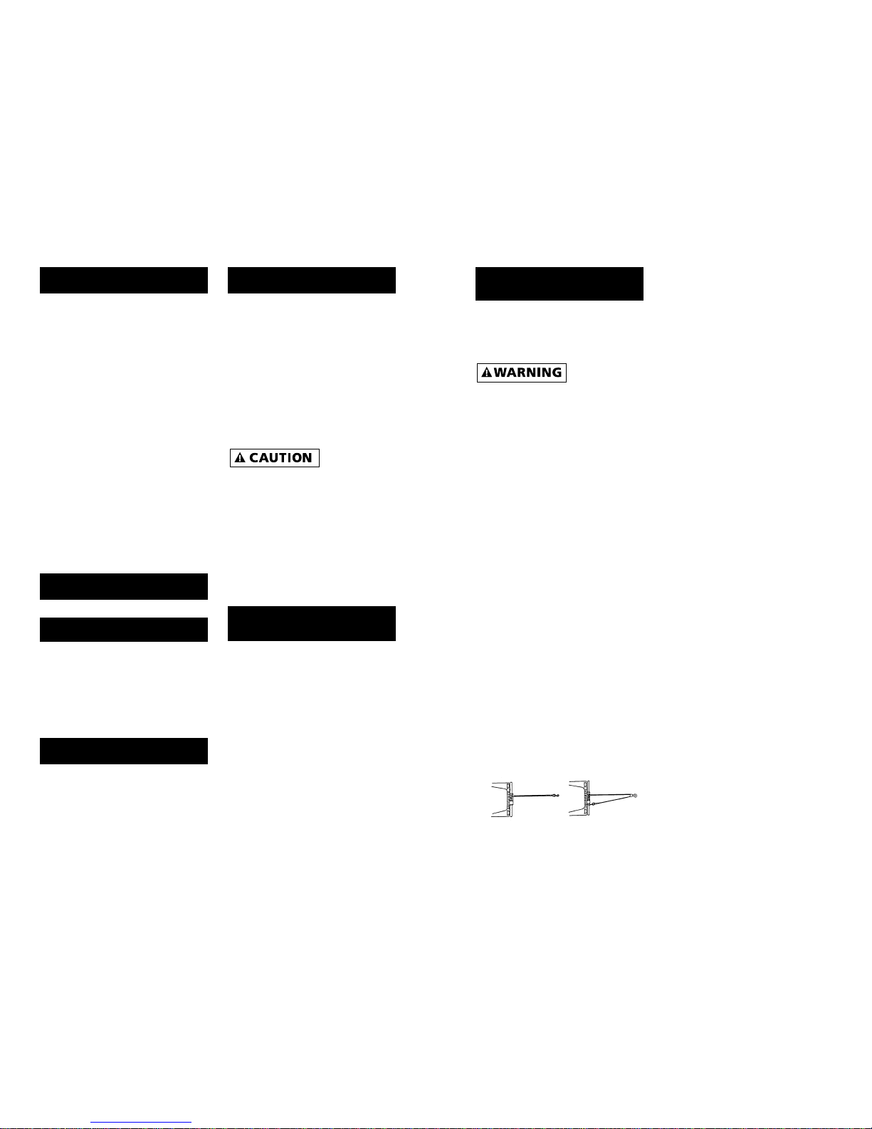
PULLING OUT THE WIRE ROPE
Move the Clutch Lever to the
“Disengage” Position as shown in
Figure 9. Pull out the wire rope and
secure to anchor or load. Check that
there are at least 5 turns left on the
Drum. Re-engage the Drum by
moving the Clutch Lever to the
“Engage” Position (Figure 9). If it
does not slide easily into engage-
ment, it may be necessary to pull
out a small amount of wire rope to
position the drum with the clutch.
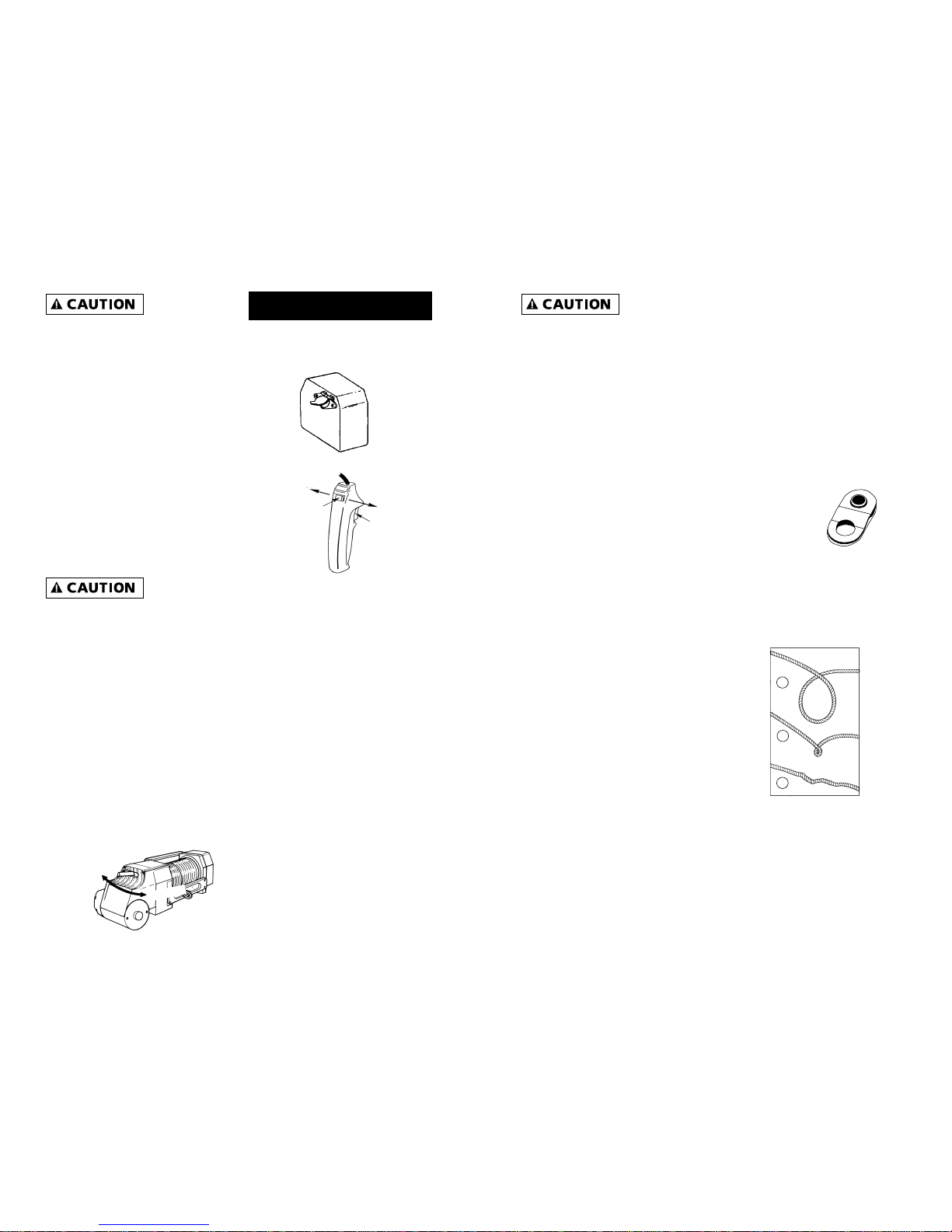
SWITCH OPERATION
The hand-held switch activates the
solenoids located in the control box.
The solenoids control the forward
and reverse operations of the winch
motor.
To connect the switch, lift the
spring loaded cover on the plug
receptacle (see Figure 10). The plug
on the switch cord is keyed to fit
into the socket only one way.
The trigger on the switch returns to
the “off” position when released
(Fig. 11, Item A). The slide button
on the back of the switch deter-
mines the direction of drum rota-
tion for “Rope In” or “Rope Out”
operations (Figure 11, Item B). The
slide is fitted with an interlock so
that the motor cannot be reversed
if the trigger is depressed. To
change direction, release the trig-
ger, move the slide button, and
depress the trigger again.
The switch
assembly must
be kept free of dirt and moisture to
ensure safe operation.
TIPS F0R EXTENDING THE LIFE OF
YOUR WINCH
1. BREAK-IN. Winch life and perfor-
mance will be greatly enhanced
by progressive break-in. We rec-
ommend 1,000 to 1,200 feet of
pulling, the first 350 feet pulling
a vehicle without the brakes
applied and during the remainder
the brakes can be applied pro-
gressively harder.
Note:
A. Installing the wire rope is not
included in the “break-in”
period.
B. Check tightness of all mount-
ing bolts after “break-in.”
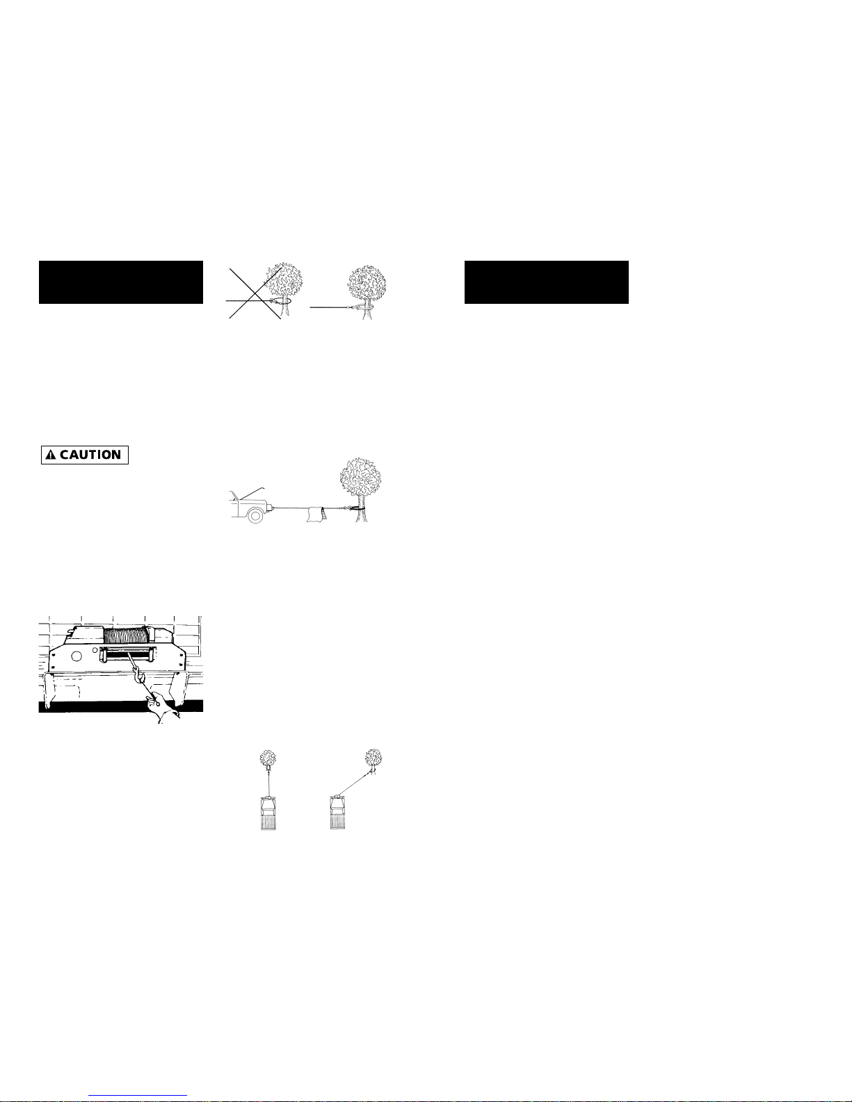
2. KEEP A TIGHTLY WOUND WIRE
ROPE DRUM. Do not allow the
wire rope to become loosely
wound. A loosely-wound drum
allows a wire rope under load to
work its way down into the layers
of wire rope on the drum. When
this happens, the wire rope may
become wedged within the body
of the windings, damaging the
wire rope. To prevent this prob-
lem, keep the wire rope tightly
and evenly wound on the drum
at all times. During winching,
periodically check to see that the
wire rope is winding on evenly. A
good practice is to rewind the
wire rope under tension after
each use. One way to do this is to
attach the hook to a stationary
object at the top of a small hill or
incline and winch your vehicle up
the incline.
3. DO NOT ALLOW MOTOR TO
OVERHEAT. Remember, the winch
is only for intermittent use.
During long or heavy pulls the
motor will get hot. The internal
parts will be hotter than the case.
To check the motor temperature,
stop winching and carefully touch
the end of the motor. If the end
of the motor is uncomfortably
warm, allow the motor to cool
before continuing. Keep the
engine running to recharge the
battery during this break.
4. USE A PULLEY BLOCK FOR HEAVY
LOADS. To maximize winch and
wire rope life, use a pulley block
(Part No. 7750A) to double line
heavier loads. (Fig 12)
5. The pull required to start a load
moving is often much greater
than the pull required to keep it
moving. Avoid frequent stopping
and starting during a pull.
6. PREVENT KINKS BEFORE THEY OCCUR.
OPERATION
Figure 9
Disengage
Engage
10
Figure 10
Figure 11
Rope
Out Rope
In
B
A
a
b
c
a.This is the start of a kink. Wire rope
should be straightened.
b.The wire rope was pulled and loop has
tightened into a kink. Wire rope is now
permanently damaged and must be
replaced.
c. The result of kinking is that each
strand pulls a different amount causing
strands under greatest tension to break
and reduce load capacity. The wire rope
must be replaced. 11
Figure 12

12
7. Equipping the winch with a roller
fairlead (Part No. 2539) will sub-
stantially reduce wear on the wire
rope during angle pulls. The
rollers eliminate heavy rubbing
and abrasion to the wire rope.
After the first 10 hours of opera-
tion: Change Worm Gearbox oil (see
Figure 13 for location of drain hole
and level plug). Check tightness of
mounting bolts and electrical con-
nections.
Monthly: Check tightness of all
electrical connections and remove
any dirt or corrosion that may
have accumulated. Check oil level
in worm gearbox. Oil level should
be maintained to the lower edge
of the plug hole with the winch in
the upright position as shown in
Figure 13. After 50 hours of winch-
ing or annually: Change Worm
Gearbox oil.
The spur and worm gear boxes are
self contained and individually lubri-
cated. The spur gearbox is factory
filled for life with BP Energrease
FGL which is suitable for the majori-
ty of climates. In extreme climates,
contact Superwinch for advice.
Note: EP (Extreme Pressure) addi-
tives can damage copper based
alloys like phosphor bronze used for
the worm gear and we do not rec-
ommend their use in the worm gear
box. If any doubt exists, consult
your lubricant supplier’s technical
department. The drum bearings and
splined drum clutch are lubricated
with molydisulphide loaded bearing
grease.
REPLACING THE WIRE ROPE
Never substitute a heavier or lighter
wire rope. Never use rope made of
any material other than wire.
Always replace damaged wire rope
with the manufacturer’s identical
replacement part (see Replacement
Parts list). Any substitution must be
IDENTICAL in strength, quality, lay
and stranding. Pass attaching end of
wire rope through the hawse and
attach into the drum.
It is important that the wire rope be
wound tightly on the drum. A good
way to do this is to attach the wire
rope hook to a fixed object at the
top of a slight incline, then winch
the vehicle up the incline.
Figure 13
Level Plug Drain Plug
MAINTENANCE
LUBRICATION
Climate
Arctic
Temperate
Tropical
Temperature
5 to 59 F
32 to 86 F
68 to 122 F
Spur Gearbox
BP to Energrease FGL*
Worm Gearbox
SAE 90 oil
SAE 85/140 oil
SAE 140 oil
Reference
Number Description Part Number Qty
REPLACEMENT
PARTS LIST
13
*Available from Superwinch
1 Wormbox Assembly (includes 2,3,7) 85-90170 1
2 Oil Seal 4-22-5572103 1
3 Plug 4-29-224 2
4 Wormset 85-95019 1
5 Needle/Roller Thrust Bearing 7721 1
6 Needle Bearing 4-12-25322013 1
7 Thrust Bearing 4-07-2542203 1
8 Thrust Washer 4-03-2542203 2
9 Location Plug 7667 1
10 Oil Seal 4-22-2535073 1
11 O-Ring 4-21-6543 1
12 Bearing Carrier 7654 1
13 Spring Pin 4-56-401003 1
14 Clutch Member 7659 1
15 Retaining Ring 4-24-4053183 1
16 O-Ring 4-21-7813 1
17 Clutch Assembly (includes 18, 19, 20, 21, 22, 23) 85-90174 1
18 Clutch Shaft 7676 1
19 Operating Lever 7673 1
20 O-Ring 4-22-6423 1
21 Spring Pin 4-56-602603 1
22 Ball 4-54-79324 1
23 Spring 4-31-7629510223 1
24 Support Housing (includes 25) 85-90138 1
25 Flanged Bearing 7653 2
26 Rope Drum Assembly 2 5/8" (includes 27) 8578 1
27 Socket Set Screw 4-40-081003 1
28 Gear Housing 85-90394 1
29 Cover 7649 1
30 Gasket 7689 1
31 Gear Motor 32T 85-54008 1
32 Gear Intermediate 59/20T 85-90171 1
33 Gear, Wormshaft 46T 7666 1
34 Retaining Ring 4-24-19227103 1
35 Retaining Ring 4-26-1618123 1
36 Spacer 7686 1
37 Key 7764 1
38 Ball Bearing 94-23079-05 1
39 Brake Shoe 317 1
40 Brake Spring 320 1
41 Motor Cover 7683 1
42 Gasket 7689 1
43 M8 Lock Washer 4-51-0823 1
44 Screw M5 x 50 7691 1
45 Motor 12 Volt 7682-I 1

15
REPLACEMENT
PARTS LIST
Reference
Number Description Part Number Qty
14
46 Shim 4-01-8090073 AR
47 Shim 4-01-8090123 AR
48 M6 x 25 Socket Head Cap Screw 4-36-0602522 16
49 M6 Lock Washer 4-51-0623 16
50 M8 x 20 Socket Head Cap Screw 4-36-0802022 8
51 M8 Lockwasher 4-51-0823 6
52 5/16-24 UNF Nut 180 3
53 Hawse Fairlead (includes 50,51) 2504 1
54 Base Plate Assembly 85-90148 1
55 #10 x 3/4 Sheet Metal Screw 94-23160-08 1
56 Bracket Solenoid 94-20118 1
57 Flange Nut 94-23149-01 2
58 12V Solenoid 92-20172 2
59 #1 Buss Bar 92-20126 2
60 #10-32 Flange Nut 92-23149-01 2
61 #10-32 x 1/2 Machine Screw 92-23125-01 2
62 M8 x 16 Hex Head Cap Screw 4-32-0801622 2
63 Front Buss Bar Assembly 92-12385 1
64 5/16 Lock Washer 92-23057-03 1
65 5/16-18 Hex Nut 92-23034-04 1
66 Top Buss Bar 92-12383 1
67 #8-32 Flange Nut 90-20149-06 2
68 Control Box Cover 7709 1
69 Socket Half Connector Assembly 90-22115 1
70 #8-32 x 5/8 Machine Screw 90-23032-03 2
71 #2 GA 76" Lead Wire Ass'y (2404) 92-20187-04 1
72 #2 GA x 30" Lead Wire Ass'y Yellow 94-20187-27 1
73 #2 GA x 30" Lead Wire Ass'y Red 94-20187-26 1
74 #2 GA x 30" Lead Wire Ass'y Blue 94-20187-32 1
75 #6 GA 62" Lead Wire Ass'y 92-20187-05 1
76 #10 GA 30" Lead Wire Ass'y 94-20187-33 1
77 Remote Control Ass'y 90-22117 1
78 5/16 x 150 ft. Wire Rope Ass'y 2562 1
79 Hook Assembly 94-20116 1
80 Hand Saver 89-32300 1
81 Solenoid Pack Pre-Wired 94-23373-01 1
NS Roller Fairlead 2539 1
NS Tie Strap 7713 1
NS BP Energrease FGL (Enough for one relube) 94-23284-01 1
NS M8 x 20 Hex Head Cap Screw 4-33-0802022 2
NS Denotes Not Shown AR Denotes As Required

TROUBLESHOOTING
CHART NOTES
Motor will not operate 1. Damaged or stuck 1. CAUTION: Disengage
or motor runs in one solenoid; most likely clutch before perform-
direction only caused by not holding ing this test to prevent
the inner nut to keep the powering the wire rope
stud from turning when drum. If a solenoid sticks
attaching wire to solenoid once, it is likely to stick
again and must be
replaced immediately.
Tap solenoid to free
stuck contacts. Check
by applying voltage to
the small solenoid ter-
minal. Be sure solenoid
is grounded back to
source. A solenoid that
is not stuck will make an
audible click when first
energized
2. Switch inoperative 2. Replace Switch
3. Broken wire or bad 3. Check for poor connec-
connection tions. CAUTION: Always
use two wrenches
(spanners)
4. Damaged motor 4. Replace or repair motor
5. Solenoids not grounded 5. Check the ground path
between battery
negative and solenoid base
Winch will not shut off 1. Solenoid stuck “on” 1. If solenoid sticks on,
reverse direction and hold
trigger switch on until the
power lead can be discon-
nected. A safety on-off
switch is available as an
accessory (p/n 1562)
Motor runs extremely hot 1. Long period of operation 1. Allow to cool
2. Damaged motor 2. Replace or repair motor
3. Armature dragging 3. Replace or repair motor
Motor runs but with 1. Weak battery 1. Recharge or replace
insufficient power or battery. Check charging
line speed system
2. Battery to winch wire 2. Use larger gauge wire.
too long Must be 2AWG or larger
3. Poor battery connection 3. Check battery terminals for
corrosion. Clean, retighten
and coat with thin film of
grease to prevent further
corrosion
4. Poor ground 4. Check and clean connections
5. Insufficient charging system 5. Use larger system
Motor runs but drum 1. Clutch not engaged 1. Engage clutch
does not turn
Winch runs backwards 1. Motor wires reversed 1. Recheck wiring
2. Solenoids wired incorrectly 2. Recheck wiring
Symptom Possible Cause(s) Corrective Action
16 17

18 19
NOTES WARRANTY REPAIR CENTERS
USA
Superwinch Inc.
Winch Drive
Putnam, CT 06260
860-928-7787
Electric Motor Repair
2010 North 4th Street
Minneapolis, MN 55411
612-588-4693
Berens & Associates
124 Hegenberger Loop
Oakland, CA 94621
888-540-2858
J & L Equipment
9205 NE 349th Street
Lacenter, WA 98629
888-353-3298
Zorko’s Alternator Service
241 Wells Road
Home, PA 15747
800-468-5055
Electric Motors of Iowa
50 Commercial Court
Iowa City, IA 52246
319-354-4040
CANADA
Torcan Equipment
163 Buttermill Ave., Unit 5
Concord Ont. L4K 3X8
905-761-8816
Harold Supply
3 Southerland Ave.
Sudbury Ont. P3C 3A7
705-761-4455
ABC Rentals
201 Regent Ave. W
Winnipeg MB R2C 1R3
204-224-1760
Moncton Elec. Motor LTD
253 Collishaw St.
Moncton NB E1C 9R2
506-859-7505
Les Equipment Twin
10401 Parkway Blvd.
Ville D’Anjou, Quebec H1J 1R4
514-353-1190
Buffalo Industries
251 Princess Street
Winnipeg, Manitoba R3B 1M1
204-942-1951
Air Electric Service
6739 76th Avenue
Edmonton, Alberta T6B 0A9
780-465-0906
Muskoka Auto Parts
11King William St.
Huntsville, Ont. P1H 2K8
705-789-2321
Lou Dennis Auto
Hiway 11 South
Sundridge, Ont. P0A 1Z0
705-384-5345
Walkwood Supply
35 Wellington St.
Lindsay, Ont K9V 4S1
705-324-2156
Bobcaygeon Auto and Marine
91 Main St.
Bobcaygeon, Ont. K0M 1A0
705-738-2317
MAP Bracebridge
19 Taylor Rd.
Bracebridge, Ont. P1L 1W3
705-645-8785
MAP Fenelon Falls
165 Lindsay St.
Fenelon Falls, Ont. K0M 1N0
705-887-6232
Argo Dist.
9431 63rd Avenue
Edmonton, Alberta T6B OG2
403-438-4443
UNITED KINGDOM
Superwinch, LTD
Abbey Rise, Whitchurch road
Tavistock, Devon PL19 9DR
+44 (0) 1822 614101
WORLDWIDEContact your Local
Superwinch Distributor or call Superwinch.

MANUAL DEL PROPIETARIO
INSTALACIÓN • OPERACIÓN • MANTENIMIENTO
PRECAUCIONES DE SEGURIDAD
PIEZAS DE REPUESTO
HUSKY 8500
Cabrestante eléctrico
de 12 Voltios CD
Nº de Pieza 2401
LEAY ENTIENDA ESTE MANUAL ANTES DE
INSTALAR Y OPERAR SU PRODUCTO
SUPERWINCH.
Superwinch, Inc. Superwinch, Ltd.
Winch Drive Abbey Rise, Whitchurch Road
Putnam, CT 06260 Tavistock, Devon PL 19 9DR
E.U.A. Inglaterra
Tel. (860) 928-7787 Tel. +44 (0) 1822 614101
Fax (860) 928-1143 Fax +44 (0) 1822 615204
VALID WORLDWIDE
LIMITED WARRANTY
Superwinch Inc. (“Seller”) warrants to the original buyer (“YOU”) all parts and components except
wire rope to be free of defects in materials and workmanship for a period of ONE (1) year from
provable date of purchase. Any Superwinch product which is defective will be repaired or replaced
without charge to you, upon compliance with these procedures. The warranties set forth herein
are exclusive and in lieu of all other warranties, whether oral or written, express or implied.
LIMITED WARRANTY PERFORMANCE PROCEDURE
Upon discovery of a defective Superwinch product, you shall mail to the Seller at his factory or to
any Factory Authorized Service Center written notice of such defect and mail, ship or otherwise
deliver the defective Superwinch, postage or shipping prepaid. Repairs or replacements by Seller
under this Limited Warranty will normally be accomplished within fifteen (15) business days after
receipt of the defective Superwinch. Seller or its Authorized Agents may make reasonable charges
for parts and labor for repairs not covered by this Limited Warranty.
WARRANTY AND REMEDY LIMITATIONS AND EXCLUSIONS
Repair and/or replacement of the defective Superwinch or component part thereof as provided
herein is the exclusive remedy for you. The following exclusions or limitations of warranties and
limitations of remedies shall be expressly applicable:
A. Express Warranties. Seller Warrants that the Superwinch is as described in the ”Superwinch
Owner’s Manual” provided herewith; no other express warranty is made in respect to the
Superwinch. If any model or sample was shown to you, such model or sample was used for illustra-
tive purposes only, and shall not be construed as a warranty that the Superwinch will conform to
the sample or model. SELLER MAKES NO EXPRESS WARRANTY WITH RESPECT TO THE WIRE ROPE
INCORPORATED IN THE PRODUCT.
B. Implied Warranty. The implied warranty of merchantability and all other implied warranties
shall only extend from the provable date of purchase for one (1) year. The wire rope is sold ”as is,”
without any implied warranties. Some states within the U.S.A. do not allow limitations on how
long an implied warranty lasts, so the above limitation may not apply to you.
C. Incidental and Consequential Damages. SUBJECT TO THE SELLER’S LIMITED WARRANTY OBLIGA-
TIONS SET FORTH HEREIN, SELLER SHALL NOT BE RESPONSIBLE FOR INCIDENTAL DAMAGES OF
ANY KIND, OR FOR CONSEQUENTIAL DAMAGES TO PROPERTY, LOSS OF PROFITS AND LOSS OF USE
WHICH MAY BE CAUSED BY ANY DEFECT IN, OR MALFUNCTION, OR FAILURE OF THE ENCLOSED
SUPERWINCH. SOME STATES WITHIN THE USA DO NOT ALLOW THE EXCLUSION OR LIMITATION OF
INCIDENTAL OR CONSEQUENTIAL DAMAGES, SO THE ABOVE LIMITATION OR EXCLUSION MAY
NOT APPLY TO YOU.
D. Condition of Warranty. Seller shall not be required to comply with its warranty duties provided
herein if the defect, malfunction, or failure of the Superwinch was caused by damage (not resulting
from defective or malfunctioning components) or unreasonable use by you. Unreasonable use shall
include, but not be limited to, the failure to provide reasonable and necessary maintenance or
installation or use of the Superwinch without compliance with the instructions contained in the
Superwinch Owner’s Manual, and subjecting the Superwinch to loads in excess of the load listed in
the Owner’s Manual for the particular model number. Seller’s liability under this warranty or for any
loss or damage to the Superwinch product shall not exceed the cost of correcting the defects in or
replacing the Superwinch product, and upon expiration of the warranty period, all such liability
shall terminate. The agents, dealers and employees of the Seller are not authorized to make modifi-
cations to this warranty, or additional warranties binding on the Seller. Accordingly, additional state-
ments, whether oral or written, do not constitute warranties and should not be relied upon.
LEGAL REMEDIES OF BUYER
This Limited Warranty gives you specific legal rights, and you may also have other rights which
may vary from state to state within the USA and from country to country. You also have implied
warranty rights. In the event of a problem with Limited Warranty service or performance, you may
be able to go to small claims court, a state court, or federal district court in the USA or to appro-
priate jurisdictions outside the USA.
INQUIRIES
Any inquiries regarding compliance with warranties provided herein may be addressed in writing
to: Superwinch Inc., Winch Drive, Putnam, CT 06260, USA or to: Superwinch Ltd., Abbey Rise,
Whitchurch Road, Tavistock, Devon PL 19 9DR, England.
LIMITED WARRANTY
94-12601 Rev H 02/07/00

22
Gracias por comprar un Husky 8500 de Superwinch. Éste ha sido diseñado y
fabricado para darle años de operación sin problemas. Esperamos que esté
satisfecho con su rendimiento. Si no lo está por cualquier motivo, por favor
comuníquese con nuestro Departamento de Servicio al Cliente:
(860) 928-7787 en E.U.A.; +44 (0) 1822 614101 en Inglaterra.
Cuando solicite información o piezas de repuetso, siempre dé la siguiente
información:
1. Número de Pieza del Cabrestante (2401)
2. Número de Serie (se encuentra en la pieza de fundición del
soporte del tambor)
3. Número de Pieza (se encuentra en la sección de la Lista de
Piezas de repuesto de este manual)
4. Descripción de la Pieza
Por favor lea y entienda este Manual del Propietario antes de instalar y usar
su cabrestante. Ponga particular atención a la Información General de
Seguridad. Su cabrestante es una máquina muy poderosa. Si se usa de man-
era insegura o incorrecta, existe la posibilidad de que cause daños a la
propiedad o lesiones personales. En este cabrestante hemos incluido varias
características de seguridad para reducir al mínimo esta posibilidad. No
obstante, a fin de cuentas su seguridad dependerá de su precaución al usar
este producto. Ponga particular atención a las notas de precau-
ción precedidas del símbolo de arriba. Las notas
contienen consejos para su protección.
La instalación correcta de su cabrestante es un requisito para su fun-
cionamiento correcto. Si pretende instalarlo en el extremo delantero de su
vehículo, use un juego de montaje que haya sido diseñado y fabricado por
Superwinch para alojar su cabrestante y ajustarse a su vehículo.
Note los requisitos eléctricos del Husky 8500 que compró: Número de Pieza
2401, sistema de 12 Volts CD ÚNICAMENTE.
¡Felicidades por su elección!
INTRODUCCIÓN
Descripción Cantidad
Conjunto de cabrestante con cable de alambre y escobén 1
Tornillos de montaje M10 x 50 mm 4
Rondanas de presión M10 4
Tornillo de tierra de 5/16" x 3/4" de largo 1
Rondana de presión de 5/16" 1
Manual del Propietario 1
Barra protectora para manos 1
Control Remoto 1
Tiras para atar cables 5
Conjunto de cable de corriente Nº 6 Ga. de 1.57 m (62") negro 1
(del cabrestante a la tierra de la batería)
Juego de llaves Allen de 6 mm, 4 mm y 1/4" 1
Separadores de 21 mm de largo 4
Esta caja contiene los siguientes artículos. Por favor desempáquelos cuida-
dosamente. Lea las instrucciones antes de comenzar.
DESEMPACADO
CARACTERÍSTICAS
23
Motor Eléctrico - Disponible en 1.9
HP pico (1.4 kw) de potencia.
Reducción de engranes primaria -
Engranes de corona de níquel-
acero cementado en una carcasa
de aluminio tratado térmicamente
y engrasado de por vida.
Reducción de engranes final -
Rueda para sinfín de bronce fos-
fórico con centro de acero impul-
sada por tornillo sinfín cementado,
maquinado y pulido de níquel-
acero que giran en rodamientos de
bolas y de rodillos sustanciales
montados en una carcasa de alu-
minio tratado térmicamente y
aceitado para garantizar una larga
vida.
Frenado - La acción del sinfín y el
engrane sinfín proporciona una
acción de freno sustancial -sin ba-
latas que se desgastes ni mecanis-
mos delicados que se rompan.
Tambor - De acero forjado que
funciona en rodamientos de
copolímero sin mantenimiento con
freno cargado por resorte para evi-
tar sobrecarga al tirar hacia afuera
el cable de alambre.

Rendimiento*
CARACTERÍSTICAS
(CONT.)
Capa del Cable Capacidad de Tiro Máxima
De Alambre lbs kg
1 8,500 3855
2 7,000 3175
3 5,950 2699
4 5,175 2347
5 4,575 2075
6 4,100 1860
Corriente
Carga Veloc. del motor
lbs kg f/min m/min Amps
0 0 18.3 5.6 71
2,000 907 9.6 2.9 140
4,000 1814 5.5 1.7 224
6,000 2722 3.3 1.0 300
8,000 3629 1.7 0.5 380
8,500 3856 1.5 0.4 405
SERVICIO
INTERMITENTE
Un cabrestante eléctrico es como
cualquier otra herramienta eléctri-
ca de motor, como un taladro o
sierra eléctricos. No debe permitir
que el motor se caliente excesiva-
mente. Las precauciones normales
extenderán la vida de su motor.
Mantenga la duración de los tiros
tan corta como sea posible. Si el
extremo del motor se calienta incó-
modamente al tacto, detenga el
tiro y permita que el motor se
enfríe. Si el motor del
cabrestante
entra en pérdida, no siga aplicán-
dole corriente.
Carga de Trabajo* . . 3855 kg (8,500 lb)
Carga de Pérdida . . . 4173 kg (9,200 lb)
Cable de
Alambre. 8 mm x 45.72 m (5/16" x 150')
Voltaje . . . . . . . . . . . . . . . 12 Voltios CD
Motor . . . . . . . . . . . . . . . . . . . . . 1.9 HP
Relación de Engranes . . . . . . . . . . 229:1
Peso . . . . . . . . . . . . . . . 47.2 kg (104 lb)
*Basado en el desempeño de la 1ª capa.
ESPECIFICACIONES
24
Embrague de Tambor - Operado
por medio de una palanca de
movimiento fácil (pintada de rojo)
que desengrana el tambor para
permitir que se tire del cable de
alambre hacia afuera sin usar co-
rriente. El embrague del tambor
tiene múltiples estrías para tener
una presión de bajo contacto.
Solenoides de Control (rele-
vadores) - Los solenoides de par en
estuche que pueden instalarse
directamente en el cabrestante o
de ma- nera remota, según se
requiera.
Control Remoto - El control remoto
de mano de 3.66 m (12 pies) con
interruptor de reversa interblo-
queante y gatillo, está diseñado
con las mismas normas que el
cabrestante.
Montaje - La posición de sujeción
permite su montaje en plataforma
o en chasís, solamente en el modo
de arrollado por debajo.
25
Su cabrestante HUSKY 8500 es una
máquina poderosa. Trátela con
respeto, úsela con precaución y siga
siempre estas normas de seguridad.
El cable de
alambre puede
romperse antes de que el cabrestante
entre en pérdida. Para cargas pesadas,
use un bloque de poleas para reducir la
carga sobre el cable de alambre.
1. El cabrestante HUSKY 8500 está
clasificado para una capacidad de
3,856 Kg (8,500 lb). NO LO
SOBRECARGUE. NO INTENTE
TIRAR DE CARGAS PESADAS POR
TIEMPO PROLONGADO. NO
MANTENGA LA CORRIENTE AL
CABRESTANTE SI EL MOTOR
ENTRA EN PÉRDIDA. Las sobre-
cargas pueden dañar el
cabrestante y/o el cable de alam-
bre y crear condiciones inseguras
de operación. PARA CARGAS
PESADAS, RECOMENDAMOS EL
USO DEL CONJUNTO DE BLOQUE
DE POLEAS Y GANCHO
OPCIONAL (Nº DE PIEZA 7750A)
PARA DUPLICAR LA LÍNEA DE
CABLE DE ALAMBRE (FIGURA 1).
Esto reduce la carga sobre el
cabrestante y el esfuerzo del
cable de alambre en un 50%
aproximadamente. Si sujeta el
cable al vehículo, sujételo al
chasís u otra pieza que soporte el
peso. El motor del vehículo debe
estar funcionando durante el
funcionamiento del cabrestante
para reducir al mínimo el des-
gaste de la batería y aumentar al
máximo la potencia y velocidad
del cabrestante. Si se realizan
tiros considerables con el motor
apagado, la batería puede estar
demasiado descargada como
para volver a arrancar el motor.
2. APRENDA A USAR SU
CABRESTANTE DESPUÉS DE LEER
Y ENTENDER ESTE MANUAL.
Después de instalar el
cabrestante, practique su uso
para familiarizarse con éste para
cuando surja la necesidad de
usarlo. Revise periódicamente la
instalación del cabrestante para
asegurarse que los tornillos estén
apretados.
3. NO «mueva» su vehículo para
ayudar al cabrestante a tirar de
una carga. La combinación del
cabrestante y el vehículo al tirar
juntos puede sobrecargar el
cable de alambre y el cabrestante
mismo.
4. MANTÉNGASE LEJOS DEL
CABRESTANTE, EL CABLE DE
ALAMBRE Y DE LA OPERACIÓN
DETIRO MISMA. MANTENGA A
LA GENTE FUERA DEL ÁREA DE
TIRO. OPERE EL CABRESTANTE
CON UNA VISTA SIN OBSTRUC-
CIONES DE LA OPERACIÓN DE
TIRO. ESTÉ SIEMPRE CONSCIENTE
DE LOS PELIGROS POTENCIALES.
PREGÚNTESE USTED MISMO QUÉ
SUCEDERÍA SI EL APAREJO DEL
CABLE DE ALAMBRE U OTRA
COSA SE ROMPE.
5. INSPECCIONE FRECUENTEMENTE
EL CABLE DE ALAMBRE Y EL
EQUIPO. UN CABLE DE ALAMBRE
DESHILACHADO CON HILOS
ROTOS DEBE REEMPLAZARSE
INMEDIATAMENTE. Siempre
reemplace el cable de alambre
con la pieza de repuesto idéntica
del fabricante (vea la Lista de
Piezas de repuesto). Toda sustitu-
ción debe ser IDÉNTICA en
fuerza, calidad, disposición y
devanado. EL EQUIPO ADI-
CIONAL usado con el
cabrestante, tal como aparejos,
ganchos, bloques de poleas,
tirantes, etc., deben ser inspec-
cionados para que no haya daños
que puedan reducir su fuerza de
rotura.
Figura 1
Línea sencilla Línea doble
INFORMACIÓN GENERAL DE
SEGURIDAD

14. NUNCA INSTALE EL
CABRESTANTE DE MODO QUE
TAPE LAS ETIQUETAS DE
ADVERTENCIA O DE INSTRUC-
CIONES. Es posible que alguien
que no haya leído este manual
tenga que verlas para entender
la operación correcta del
cabrestante.
15. Siempre opere el cabrestante
con una vista sin obstrucciones
de la operación.
16. SE RECOMIENDA QUE SE USE
UNA GUÍA para dirigir el cable
de alambre dentro del
cabrestante. Hay la posibilidad
de lesiones al operario o daños
al cabrestante si no se instala
una guía de rodillos.
17. NUNCA SUELTE EL EMBRAGUE
CUANDO HAYA UNA CARGA
EN EL CABRESTANTE.
18. GUARDE EL CONJUNTO DEL
INTERRUPTOR REMOTO EN UN
LUGAR SEGURO cuando no lo
use para evitar que lo usen los
niños o personas sin autoriza-
ción, quienes podrían lesio-
narse o lesionar a los demás.
19. NO OPERE EL CABRESTANTE
CUANDO ESTÉ BAJO LA INFLU-
ENCIA DE DROGAS, ALCOHOL
O MEDICAMENTOS.
20. SIEMPRE DESCONECTE EL
INTERRUPTOR REMOTO ANTES
DE TRABAJAR EN LA GUÍA, EL
TAMBOR DEL CABRESTANTE O
A SU ALREDEDOR (LA ZONA DE
PELIGRO), para que no se
pueda encender el cabrestante
accidentalmente.
21. NUNCA TRABAJE EN LA GUÍA,
EL TAMBOR DEL CABRESTANTE
O A SU ALREDEDOR MIENTRAS
EL CABRESTANTE ESTÉ BAJO
CARGA.
22. Cuando use su cabrestante para
mover una carga, coloque la
transmisión de su vehículo en
neutral, ponga el freno de
mano, bloquee todas las ruedas
y mantenga en funcionamiento
el motor.
23. NO USE EL CABRESTANTE PARA
RETENER CARGAS EN UN SÓLO
SITIO. Use otros medios para
asegurar cargas, como cadenas
y tirantes para atar. Superwinch
ofrece una amplia variedad de
tirantes para atar. Comuníquese
con su distribuidor Superwinch
local.
24. SÓLO USE LOS INTERRUPTORES,
CONTROLES REMOTOS Y ACCE-
SORIOS APROBADOS POR EL
FABRICANTE. El uso de compo-
nentes no aprobados puede
causar lesiones, daños a la
propiedad y puede anular su
garantía.
25. NO MAQUINE NI SUELDE
NINGUNA PIEZA DEL
CABRESTANTE. Tales
alteraciones pueden debilitar la
integridad estructural del
cabrestante y pueden anular su
garantía.
26. NO USE EL CABRESTANTE
ARROLLANDO POR ENCIMA
DEL TAMBOR.
27. El cable de alambre de su
cabrestante Husky 8500 tiene
una «tira de seguridad» roja de
unos 3 metros (10') en cada
extremo. La «tira de seguridad»
del extremo del cable de alam-
bre que se sujeta al tambor le
advierte que el cable está casi
completamente afuera. NO use
el cabrestante en estos últimos
3 metros de cable, porque el
cable y su sujeción NO resistirán
una carga pesada. La «tira de
seguridad» del extremo del
gancho del cable le advierte
que el cable está casi total-
mente arrollado. SIEMPRE USE
LA BARRA PROTECTORA PARA
MANOS al manipular el gan-
cho (Figura 2). La pintura roja
se desgastará con el uso nor-
mal. Cuando esto suceda, usted
deberá renovar la pintura roja
ya que es una característica de
seguridad del cabrestante.
6. USE GUANTES DE CUERO PESA-
DO cuando maneje el cable de
alambre. NO DEJE QUE EL CABLE
DE ALAMBRE SE DESLICE EN SUS
MANOS. Una hebra rota puede
lesionar gravemente sus manos.
7. NUNCA USE EL CABRESTANTE
CON MENOS DE 5 VUELTAS DE
CABLE DE ALAMBRE EN EL TAM-
BOR, ya que es posible que el
cable de alambre y su sujeción
NO resistan la carga completa.
8. MANTÉNGASE ALEJADO DEL
CABLE DE ALAMBRE Y DEL GAN-
CHO CUANDO ESTÉ OPERANDO
EL CABRESTANTE. NUNCA
atraviese el gancho con los
dedos cuando enrolle o desen-
rolle los últimos centímetros de
línea. Si sus dedos quedan atra-
pados en el gancho, podría
perderlos. Use la BARRA PRO-
TECTORA PARA MANOS (Figura
2) para guiar el gancho los últi-
mos centímetros. Nunca guíe el
cable de alambre con las manos
hacia adentro o hacia afuera del
tambor.
9. NUNCA ENGANCHE EL CABLE DE
ALAMBRE SOBRE SÍ MISMO. Use
una eslinga de nilón (Nº de
Pieza Superwinch 1509 ó 2531).
Enganchar el cable sobre sí
mismo puede dañarlo (Figura 3).
10. Es una buena idea poner una
frazada pesada o un abrigo
sobre el cable de alambre cerca
del extremo del gancho cuando
tire de una carga pesada
(Figura 4). En el caso de que el
cable de alambre falle, la tela
actuará como atenuador para
evitar que el cable de alambre
latiguee. Levante la tapa del
motor de su vehículo para
aumentar la seguridad.
11. NUNCA USE SU CABRESTANTE
PARA IZAR O TRANSPORTAR
GENTE NI NINGUNA COSA QUE
CONTENGA GENTE. El
cabrestante no está diseñado
ni destinado a izar ni trans-
portar gente.
12. Su cabrestante no está diseña-
do ni destinado para opera-
ciones de izado elevado.
13. EVITE TIRAR CONTINUAMENTE
DESDE ÁNGULOS EXTREMOS,
ya que esto causará que el
cable de alambre se apile en
un extremo del tambor (Figura
5). Esto puede atorar el cable
de alambre en el cabrestante
dañando tanto el cable de
alambre como el cabrestante
mismo.
26 27
Figura 2
INFORMACIÓN
GENERAL DE SEGURIDAD
(CONT.)
INFORMACIÓN
GENERAL DE SEGURIDAD
(CONT.)
Incorrecto Correcto
Correcto Incorrecto
Figura 5
Figura 3
Figura 4

1. Desconecte la batería del
vehículo.
2. Quite la tapa del solenoide. Los
cables y los solenoides están
codificados por colores para
ayudar a su instalación. Iguale
los colores de los cables y los
solenoides al hacer las cone-
xiones del cabrestante.
3. Quite la tapa del motor.
Identifique las terminales del
motor comparándolas con el
diagrama de cableado (ver la
Figura 7).
4. Conecte los conjuntos de cable
como se muestra en el diagrama
de cableado. No conecte el cable
a la batería en este momento.
Cuando
conecte los
cables a las terminales del motor y
los solenoides (relevadores), sujete
la tuerca interior mientras aprieta
la exte-rior. No permita que giren
las terminales del motor ya que
esto romperá los cables internos.
Tenga especial cuidado para evitar
que giren las terminales del sole-
noide (relevador). Cualquier giro
puede dañarlo (vea la Figura 8).
Sus cables codificados por color y
el cable negro de diámetro delga-
do (calibre 10) deben dirigirse bajo
el cabrestante y atarse a la placa
de montaje con las tiras de atar
cable. Los cables sin codificación
por color deben dirigirse a través
de la parrilla del vehículo hacia la
batería. Use un cable 6 ga. (de
menor diámetro) para el cable de
tierra. Para proteger el cable con-
tra abrasión y/o corte, aplique
varias capas de cinta aislante
donde el cableado pueda tocar
piezas agudas de metal del
vehículo.
Todas las conexiones al motor,
solenoides y la tierra de la batería
requieren de buenas conexiones,
limpias y apretadas. La eficacia del
funcionamiento del cabrestante
está en relación directa con las
buenas conexiones eléctricas y el
tamaño adecuado de los cables.
28. Tenga precaución cuando tire
de una carga por una rampa o
pendiente. Manténgase alejado
y mantenga a la gente, masco-
tas y bienes lejos del camino de
la carga.
29. CUANDO MUEVA LENTAMENTE
UNA CARGA, RECOJA EL EXCE-
SO DE CABLE DE ALAMBRE
CON CUIDADO HASTA QUE
ÉSTE ESTÉ TENSO. DETÉNGASE,
VUELVA A VERIFICAR TODAS
LAS CONEXIONES DE TIRO.
ASEGÚRESE DE QUE TODO EL
APAREJO ESTÉ BIEN ASENTA-
DO. REVISE QUE EL CABLE DE
ALAMBRE ESTÉ CORRIENDO
CORRECTAMENTE EN TODAS
LAS POLEAS.
MONTAJE DE SU CABRESTANTE
Como su cabrestante tiene una
caja de engranes llena de aceite y
con ventilación, éste debe mon-
tarse derecho para (adaptadores)
evitar fugas de aceite.
Hay juegos de montaje Superwinch
para los vehículos más populares.
Si no puede encontrar un juego de
montaje en su localidad,
comuníquese con Superwinch a la
dirección anotada al frente de este
manual para que le den el nombre
de un distribuidor Superwinch cer-
cano a usted. Las instrucciones
detalladas de montaje se incluyen
con cada juego. Lea e instale
cuidadosamente para garantizar la
alineación correcta y un fun-
cionamiento sin problemas del
cabrestante. El montaje inco-rrecto
puede dañar el cabrestante y anu-
lar la garantía.
HERRAMIENTAS REQUERIDAS
Llaves españolas (abiertas):
(2) 9/16", (2) 1/2", (2) 7/16", (2)
3/8"
Llave de torsión:
Con capacidad de 75 lb ft e impul-
sor de 1/2"
Llave de trinquete con impulsor de
1/2"
Llaves de dado de 3/4" y 17 mm
Destornillador de cruz
INSTALACIÓN ELÉCTRICA
Este cabrestante funciona con co-
rriente directa automotriz estándar
de 12 voltios. NO CONECTE EL
CABRESTANTE A LA CORRIENTE
DOMÉSTICA DE 110 O 220V, YA
QUE PUEDE QUEMAR EL
CABRESTANTE ¡O PUEDE RECIBIR
UN CHOQUE ELÉCTRICO FATAL!
Para un funcionamiento sin proble-
mas, asegúrese siempre que la
batería esté bien cargada y man-
tenida. El rendimiento del
cabrestante depende directamente
de la calidad y capacidad de la
batería y del alternador.
Nota: Para un mejor funcionamien-
to, las fuentes de energía
recomendadas como mínimo, son
las baterías BCI grupo 27 y los
alternadores de 55 amp. Si se
reducen estas capacidades, se
reducirá el rendimiento del
cabrestante.
Cuando se use el cabrestante, el
motor del vehículo debe estar en
funcionamiento en marcha en
vacío de alta velocidad para suplir
la reserva de potencia de la
batería. Si el cabrestante soporta
un uso pesado, se recomiendan
una batería auxiliar y un alter-
nador de servicio pesado con ais-
lador de batería (Nº de Pieza
Superwinch 2216).
CONEXIÓN DE LOS CABLES
ELÉCTRICOS Las baterías
automotrices
contienen gases inflamables y
explosivos. Use protección para los
ojos durante la instalación y
quítese toda joyería metálica.
No se incline sobre la batería al
hacer conexiones.
29
INSTALACIÓN
Neg. Pos.
Amarillo
Azul
Rojo
Rojo
Amarillo
Negro
Azul
Verde
Blanco
NOTA: Si esta placa se monta en
otro lugar que no sea el
cabrestante, deberá conectarse a
tierra, de vuelta al polo negativo
de la batería.
Dirija los cables eléctricos
bajo el cabrestante en el
área provista por los separadores.
Figura 7
Figura 8
28
Sujete los cables a la
placa de montaje con las
tiras de atar cables de
plástico.
Negro de
diámetro
delgado

El conjunto
del interrup-
tor debe mantenerse libre de
tierra y humedad para garanti-
zar una operación segura.
CONSEJOS PARA ALARGAR LA
VIDA DE SU CABRESTANTE
1. RODAMIENTO INICIAL. La vida y
el rendimiento del cabrestante
pueden mejorarse grandemente
con un rodamiento inicial pro-
gresivo. Recomendamos tirar de
304.8 a 365.8 m (1,000' a 1,200').
Los primeros 106.7 m (350')
tirando del vehículo sin aplicar
los frenos y el resto aplicando
los frenos, aumentando de man-
era progresiva.
Nota:
A. La instalación del cable de
alambre no se incluye en el perío-
do de «rodamiento inicial».
B. Revise la firmeza de todos los
tornillos de montaje después del
«rodamiento inicial».
2. MANTENGA EL CABLE DE
ALAMBRE ARROLLADO FIRME-
MENTE EN EL TAMBOR. No per-
mita que se afloje el cable de
alambre. Un tambor arrollado
flojamente permite que el cable
de alambre con carga baje por
las capas de cable del tambor.
Cuando esto sucede, el cable de
alambre puede deformarse
como cuña dentro del cuerpo
del enrollado dañándose. Para
evitar este problema, mantenga
el cable enrollado firme y uni-
formemente en todo momento.
Durante el tiro, revise periódi-
camente que el cable se esté
enrollando uniformemente. Una
buena práctica es enrollarlo bajo
tensión después de cada uso.
Una manera de hacerlo es suje-
tar el gancho a un objeto esta-
cionario hasta arriba de una
pequeña colina o pendiente y
tirar de su vehículo hacia arriba
de la pendiente.
3. NO PERMITA QUE SE SOBRE-
CALIENTE EL MOTOR. Recuerde,
el cabrestante es solamente para
uso intermitente. El motor se
calentará durante los tiros largos
o pesados. Las piezas internas
estarán más calientes que la car-
casa. Para revisar la temperatura
del motor, deje de tirar y toque
cuidadosamente el extremo del
motor. Si el extremo del motor
está incómodamente caliente,
deje que se enfríe antes de con-
tinuar. Mantenga funcionando
el motor de su vehículo para
recargar la batería durante esta
pausa.
4. USE UN BLOQUE DE POLEAS
PARA CARGAS PESADAS. Para
aumentar al máximo la vida del
cabrestante y del cable de alam-
bre, use un bloque de poleas,
(Nº de Pieza 7750A), para
duplicar la línea para cargas más
pesadas (Figura 12)
5. El tirón requerido para comen-
zar a mover una carga a
menudo es mucho mayor que el
requerido para mantenerla en
movimiento. Evite paradas y
comienzos frecuentes durante el
tiro.
6. EVITE TORCEDURAS ANTES DE
QUE OCURRAN.
a. Éste es el comienzo de una torcedura.
Debe enderezarse el cable de alambre.
b. Se ha tirado del cable de alambre y el rizo
se ha apretado a una torcedura. Ahora el
cable de alambre ya está dañado permanen-
temente y debe ser reemplazado.
c. Las torceduras hacen que cada hilo tire
con diferentes tensiones haciendo que se
rompan los hilos de alambre bajo mayor
tensión y reducen la capacidad de carga. El
cable de alambre debe ser reemplazado.
Revise dos
veces su
cableado. ¡El cableado inco-rrecto
puede causar que se queme el
motor o lesiones personales!
5. Reemplace y sujete la tapa del
motor.
6. Vuelva a sujetar la tapa del sole-
noide.
7. Vuelva a conectar las terminales
positiva y luego la negativa
(tierra) de la batería.
Ponga la palanca del embrague en
la posición de «Desengranar».
Saque tirando unos metros de
cable del tambor. Cambie de
nuevo la palanca del embrague a
la posición «Engranar». Conecte el
conjunto del interruptor remoto.
Cambie el control manual a la
posición «Sacar Cable». Oprima el
gatillo momentáneamente para
comprobar la dirección del tambor
del cable de alambre. Si el tambor
gira en la dirección incorrecta,
invierta los cables verde y negro
que conectan el receptáculo del
control remoto a las pequeñas ter-
minales del solenoide.
Para evitar el
uso sin autor-
ización del
cabrestante, quite el conjunto del
interruptor y guárdelo en un área
limpia y seca, como la guantera.
PARA SACAR EL CABLE
DE ALAMBRE
Ponga la palanca del embrague en
la posición «Desengranar» como se
muestra en la Figura 9. Saque el
cable de alambre y sujételo a un
ancla o carga. Revise que hayan
quedado por lo menos 5 vueltas
en el tambor. Vuelva a engranar el
tambor poniendo la palanca del
embrague en la posición
«Engranar» (Figura 9). Si la palan-
ca no se desliza fácilmente a su
posición de engrane, puede que
sea necesario sacar un poco de
cable para alinear el tambor con el
embrague.
OPERACIÓN DEL INTERRUPTOR
El interruptor de mano activa los
solenoides ubicados en la caja de
control. Los solenoides controlan
el movimiento de avance y reversa
del motor del cabrestante.
Para conectar el interruptor,
levante la tapa de resorte del
receptáculo de la clavija (ver la
Figura 10). La clavija del cable del
inte-rruptor está codificado para
entrar en el contacto de una sola
manera.
El gatillo del interruptor vuelve a
la posición de «apagado» al soltar-
lo (Fig. 11, letra A). El botón
deslizante del reverso del interrup-
tor determina la dirección de
rotación del tambor, para «Sacar
Cable» o «Arrollar Cable» (Figura
11 letra B). El deslizador está
equipado con un interbloqueo
para que el motor no pueda fun-
cionar en reversa si se oprime el
gatillo. Para cambiar dirección,
suelte el gatillo, mueva el botón y
vuelva a oprimir el gatillo.
OPERACIÓN
Figura 9
Desengranar
Engranar
30
Figura 10
Figura 11
Arrollar
Cable Sacar
Cable
B
A
a
b
c
31
Figura 12

7. Equipar el cabrestante con una
guía de rodillos (Nº de Pieza 2539)
reducirá sustancialmente el des-
gaste del cable de alambre
durante los tiros en ángulo. Los
rodillos eliminan el roce pesado y
la abrasión al cable de alambre.
Después de las primeras 10 horas
de operación: Cambie el aceite de
la caja del engrane sinfín (vea en
la Figura 13 la ubicación del orifi-
cio de drenado y el tapón de
nivel). Revise la firmeza de los
tornillos de montaje y las cone-
xiones eléctricas.
Mensualmente: Revise la firmeza
de todas las conexiones eléctricas y
quite toda la basura o corrosión
que pueda haberse acumulado.
Revise el nivel de aceite de la caja
del engrane sinfín. El nivel de
aceite debe mantenerse en el
borde inferior del orificio del
tapón con el cabrestante en posi-
ción derecha como se muestra en
la Figura 13. Después de 50 horas
de tiro o anualmente: Cambie el
aceite de la caja del engrane del
sinfín.
Las cajas del engrane de corona y
del engrane sinfín son autónomas
y lubricadas individualmente. La
caja del engrane de corona está
llena de por vida desde la fábrica
con grasa BP Energrease FGL, la
cual es idónea para la mayoría de
los climas. En climas extremos, con-
sulte a Superwinch.
Nota: Los aditivos EP (Presión
Extrema) pueden dañar las alea-
ciones basadas en cobre, como el
bronce fosfórico usado en el
engrane sinfín y no recomendamos
su uso en la caja del engrane sin-
fín. Si tiene alguna duda, consulte
al departamento técnico de su
proveedor de lubricantes. Los
rodamientos del tambor y el
embrague estriado del tambor se
lubrican con grasa para rodamien-
tos cargada con polidisulfuro.
REEMPLAZO DEL CABLE DE
ALAMBRE
Nunca sustituya por un cable de
mayor o menor capacidad. Nunca
use otro cable hecho de ningún
otro material que no sea alambre.
Siempre reemplace el cable de
alambre dañado con la pieza de
repuesto idéntica del fabricante
(ver la Lista de piezas de repuesto).
Toda sustitución debe ser
IDÉNTICA en fuerza, calidad, dis-
posición y devanado. Pase el
extremo de sujeción del cable de
alambre por el escobén y sujételo
al tambor.
Es importante que el cable de
alambre esté firmemente arrollado
en el tambor. Una buena manera
de hacerlo es sujetar el gancho del
cable de alambre a un objeto fijo
hasta arriba de una pendiente lig-
era y tirar de su vehículo hacia
arriba en la pendiente.
32
MANTENIMIENTO
LUBRICACIÓN
Clima
Ártico
Templado
Tropical
Temperatura
de 5° a 59° F
de 32° a 86° F
de 68° a 122° F
Caja del engrane
de corona
BP Energrease FGL*
BP Energrease FGL*
BP Energrease FGL*
Caja del engrane
sinfín
Aceite SAE 90
Aceite SAE 85/140
Aceite SAE 140 33
*Disponible de Superwinch
Figura 13
Tapón de nivel Tapón de drenado
Nº de
Referencia Descripción Nº de Pieza Cant.
LISTA DE PIEZAS
DE REPUESTO
1 Conjunto de caja de sinfín (incluye 2,3,7) 85-90170 1
2 Sello de aceite 4-22-5572103 1
3 Tapón 4-29-224 2
4 Sinfín 85-95019 1
5 Rodamiento de bola/rodillo de empuje 7721 1
6 Rodamiento de aguja 4-12-25322013 1
7 Rodamiento de empuje 4-07-2542203 1
8 Rondana de empuje 4-03-2542203 2
9 Tapón de ubicación 7667 1
10 Sello de aceite 4-22-2535073 1
11 Empaque anular 4-21-6543 1
12 Transporte de rodamiento 7654 1
13 Perno de resorte 4-56-401003 1
14 Miembro de embrague 7659 1
15 Anillo retenedor 4-24-4053183 1
16 Empaque anular 4-21-7813 1
17 Conjunto de embrague (incluye 18,19,20,21,22,23) 85-90174 1
18 Flecha del embrague 7676 1
19 Palanca de operación 7673 1
20 Empaque anular 4-22-6423 1
21 Perno de resorte 4-56-602603 1
22 Bola 4-54-79324 1
23 Resorte
4-31-7629510223
1
24 Carcasa de soporte (incluye 25) 85-90138 1
25 Rodamiento con brida 7653 2
26 Conjunto del tambor del cable 66.5 mm (2 5/8'') 8578 1
(incluye 27)
27 Tornillo allen de seguridad 4-40-081003 1
28 Carcasa de engranes 85-90394 1
29 Tapa 7649 1
30 Empaque 7689 1
31 Engrane de motor 32T 85-54008 1
32 Engrane intermedio 59T/20T 85-90171 1
33 Engrane, Flecha sinfín 46T 7666 1
34 Anillo retenedor 4-24-19227103 1
35 Anillo retenedor 4-26-1618123 1
36 Separador 7686 1
37 Llave 7764 1
38 Rodamiento de bolas 94-23079-05 1
39 Balata de freno 317 1
40 Resorte de freno 320 1
41 Tapa del motor 7683 1
42 Empaque 7689 1
43 Rondana de presión M8 4-51-0823 1
44 Tornillo M5 x 50 7691 1
45 Motor de 12 voltios 7682-I 1

Nº de
Referencia Descripción Nº de Pieza Cant.
LISTA DE PIEZAS
DE REPUESTO
34 35
46 Cuña 4-01-8090073 CSN
47 Cuña 4-01-8090123 CSN
48 Tornillo allen M8 x 25 4-36-0602522 16
49 Rondana de presión M6 4-51-0623 16
50 Tornillo allen M8 x 20 4-36-0802022 8
51 Rondana de presión M8 4-51-0823 6
52 Tuerca UNF 5/16 - 24 180 3
53 Guía de escobén (incluye 50,51) 2504 1
54 Conjunto de placa base 85-90148 1
55 Tornillo para lámina Nº 10 x 3/4 94-23160-08 1
56 Soporte de Solenoide 94-20118 1
57 Tuerca con brida 94-23149-01 2
58 Solenoide de 12V 92-20172 2
59 Placa de conexión Nº 1 92-20126 2
60 Tuerca con brida Nº 10-32 92-23149-01 2
61 Tornillo de máquina Nº 10-32 x 1/2 92-23125-01 2
62 Tornillo de cabeza hexagonal M8 x 16 4-32-0801622 2
63 Conjunto de placa de conexión delantera 92-12385 1
64 Rondana de presión de 5/16 92-23057-03 1
65 Tuerca hexagonal de 5/16-18 92-23034-04 1
66 Placa de conexión superior 92-12383 1
67 Tuerca con brida Nº 8-32 90-20149-06 2
68 Tapa de la caja de control 7709 1
69 Conjunto de medio contacto del receptáculo 90-22115 1
70 Tornillo de máquina Nº 8-32 x 5/8 90-23032-03 2
71 Conjunto de cable Nº 2 Ga 1.93 m (76'') 92-20187-04 1
72 Conjunto de cable Nº 2 Ga 76.2 cm (30'') (Amarillo) 94-20187-27 1
73 Conjunto de cable Nº 2 Ga 76.2 cm (30'') (Rojo) 94-20187-26 1
74 Conjunto de cable Nº 2 Ga 76.2 cm (30'') (Azul) 94-20187-32 1
75 Conjunto de cable Nº 6 Ga 1.57 m (62'') 92-20187-05 1
76 Conjunto de cable Nº 10 Ga 76.2 cm (30'') 94-20187-33 1
77 Conjunto de control remoto 90-22117 1
78 Conjunto de cable de alambre de 8 mm x 45.72 m 2562 1
(5/16" x 150')
79 Conjunto del gancho 94-20116 1
80 Barra protectora para manos 89-32300 1
81 Paquete solenoide precableado 94-23373-01 1
NSM Escobén con rodillos 2539 1
NSM Tira para atar 7713 1
NSM Grasa BP Energrease FGL (suficiente para 1 lub.) 94-23284-01 1
NSM Tornillo de cabeza hexagonal M8 x 20 4-33-0802022 2

TABLA DE BÚSQUEDA
DE SOLUCIONES
36
El motor no funciona o fun-
ciona sólo en una dirección
El cabrestante no se apaga
El motor se sobrecalienta
El motor funciona pero el
tambor no gira
El cabrestante funciona
hacia atrás
El motor funciona, pero sin
la potencia o velocidad de
línea suficientes
1. Solenoide atascado o daña-
do; muy probablemente cau-
sado por no retener la tuer-
ca interior para evitar que el
perno girase cuando se
conectó el cable al solenoide
1. PRECAUCIÓN: Desengrane el
embrague antes de realizar
esta prueba para evitar conec-
tar el tambor del cable de
alambre. Si el solenoide se
atasca una vez, es muy proba-
ble que se vuelva a atascar y
debe ser reemplazado inmedia-
tamente. Golpee el solenoide
para liberar los contactos atas-
cados. Revise aplicando corri-
ente a la terminal pequeña del
solenoide. Asegúrese que el
solenoide esté conectado de
vuelta a la fuente. Un solenoide
que no esté atascado hará un
clic audible al ser conectado.
2. Interruptor que no funciona
4. Motor dañado
5. Solenoides sin conexión a
tierra
1. Solenoide atascado en
«Encendido»
1. Período de funcionamiento
largo
2. Motor dañado
1. Embrague no engranado 1. Engrane el embrague
1. Batería baja
2. Cable de la batería al
cabrestante muy largo
3. Malas conexiones a la batería
4. Mala conexión a tierra
5. Sistema de carga insuficiente
3. Cable roto o mala
conexión
2. Reemplace el interruptor
4. Reemplace o repare el motor
5. Revise la ruta de conexión a
tierra entre el negativo de la
batería y la base del solenoide
1. Si el solenoide se atasca en
encendido, invierta la dirección
y mantenga encendido el inter-
ruptor de gatillo hasta que el
cable de corriente pueda
desconectarse. Contamos con
un interruptor de encendido-
apagado de seguridad como
accesorio. (P/N
o
1562)
1. Deje que se enfríe
3. Reemplace o repare el motor
2. Reemplace o repare el motor
1. Recargue o reemplace la
batería. Revise el sistema de
carga
2. Use cable de mayor calibre.
Debe ser de 2 AWG o mayor
3. Revise que las terminales de la
batería no tengan corrosión.
Limpie, vuelva a apretar y
recubra con una película delga-
da de grasa para evitar corro-
sión adicional.
4. Revise y limpie las conexiones
5. Use un sistema más grande
3. Revise que no haya una mala
conexión. PRECAUCIÓN:
Siempre use dos llaves de
españolas (abiertas)
3. Arrastre de armadura
1. Cables del motor invertidos
2. Solenoides cableados incorrec-
tamente
1. Vuelva a revisar el cableado
2. Vuelva a revisar el cableado
Síntoma Causa Probable Acción Correctiva
37
NOTAS

NOTAS
38 39
CENTROS DE REPARACIÓN
DE GARANTÍA
ÉUA
Superwinch Inc.
Winch Drive
Putnam, CT 06260
860-928-7787
Electric Motor Repair
2010 North 4th Street
Minneapolis, MN 55411
612-588-4693
Berens & Associates
124 Hegenberger Loop
Oakland, CA 94621
888-540-2858
J & L Equipment
9205 NE 349th Street
Lacenter, WA 98629
888-353-3298
Zorko’s Alternator Service
241 Wells Road
Home, PA 15747
800-468-5055
Electric Motors of Iowa
50 Commercial Court
Iowa City, IA 52246
319-354-4040
CANADA
Torcan Equipment
163 Buttermill Ave., Unit 5
Concord Ont. L4K 3X8
905-761-8816
Harold Supply
3 Southerland Ave.
Sudbury Ont. P3C 3A7
705-761-4455
ABC Rentals
201 Regent Ave. W
Winnipeg MB R2C 1R3
204-224-1760
Moncton Elec. Motor LTD
253 Collishaw St.
Moncton NB E1C 9R2
506-859-7505
Les Equipment Twin
10401 Parkway Blvd.
Ville D’Anjou, Quebec H1J 1R4
514-353-1190
Buffalo Industries
251 Princess Street
Winnipeg, Manitoba R3B 1M1
204-942-1951
Air Electric Service
6739 76th Avenue
Edmonton, Alberta T6B 0A9
780-465-0906
Muskoka Auto Parts
11King William St.
Huntsville, Ont. P1H 2K8
705-789-2321
Lou Dennis Auto
Hiway 11 South
Sundridge, Ont. P0A 1Z0
705-384-5345
Walkwood Supply
35 Wellington St.
Lindsay, Ont K9V 4S1
705-324-2156
Bobcaygeon Auto and Marine
91 Main St.
Bobcaygeon, Ont. K0M 1A0
705-738-2317
MAP Bracebridge
19 Taylor Rd.
Bracebridge, Ont. P1L 1W3
705-645-8785
MAP Fenelon Falls
165 Lindsay St.
Fenelon Falls, Ont. K0M 1N0
705-887-6232
Argo Dist.
9431 63rd Avenue
Edmonton, Alberta T6B OG2
403-438-4443
REINO UNIDO
Superwinch, LTD
Abbey Rise, Whitchurch road
Tavistock, Devon PL19 9DR
+44 (0) 1822 614101
EN TODO EL MUNDO
Comuníquese con su Distribuidor local de
Superwinch o llame a Superwinch.
Table of contents
Languages:
Other Superwinch Other manuals
Popular Other manuals by other brands

DURKOPP ADLER
DURKOPP ADLER 739 manual

Parkside
Parkside 291643 Translation of the original instructions

CertainTeed
CertainTeed Bufftech installation instructions

MTM HYDRO
MTM HYDRO Professional Foam Lance user manual

National Flooring Equipment
National Flooring Equipment 3397 Service manual

Or-Fab
Or-Fab 83241 installation instructions