Superwinch EP/EPi6.0 User manual

OWNER’S MANUAL
INSTALLATION • OPERATION • MAINTENANCE
SAFETY PRECAUTIONS • REPAIR PARTS
EP/EPi6.0 and EP/EPi9.0
12 & 24 Volt DC Electric Winch
READ AND UNDERSTAND THIS MANUAL BEFORE INSTALLATION
AND OPERATION OFYOUR SUPERWINCH PRODUCT.
CAUTION
!
Superwinch, Inc. Superwinch, Ltd.
Winch Drive Abbey Rise, Whitchurch Road
Putnam, CT 06260 Tavistock, Devon PL 19 9DR
U.S.A. England
Tel. (860) 928-7787 Tel. +44 (0) 1822 614101
Fax (860) 963-0811 Fax +44 (0) 1822 615204
90-10902 Rev B 5/19/04

2
Thank you for purchasing an EP series winch from Superwinch. It has been designed
and manufactured to provide years of trouble-free operation. We hope you will be
pleased with its performance. If you are not, for any reason, please contact our Customer
Service Department: (860) 928-7787 USA; +44 (0) 1822 614101 England.
When requesting information or ordering replacement parts; always give the
following information:
1. Winch Part Number
2. Serial Number
3. Part Number
4. Part Description
Note: Winch specifications and equipment may vary from country to country.
The responsibility for safe installation and operation of this winch ultimately rests
with you, the operator. Read and understand all safety precautions and operating
instructions before installing and operating the winch. Careless winch operation
can result in serious injury and/or property damage.
Throughout this manual, you will find notations with the following headings:
Indicates an imminently hazardous situation which, if not
avoided, will result in death or serious injury.
Indicates a potentially hazardous situation which, if not
avoided, could result in death or serious injury.
Indicates a potentially hazardous situation which, if not
avoided, may result in minor or moderate injury. This
notation is also used to alert against unsafe practices.
The following symbols on the product and in the Owner's manual are used:
Note:Indicates additional information in the installation and operation
procedures of your winch.
Correct installation of your winch is a requirement for proper operation.
Please Note: Winch is designed primarily for intermittent applications. This winch
is not designed to be used in hoisting applications and Superwinch does not warrant
it to be suitable for such use. Please contact our Customer Service Department for
further information.
Congratulations on your choice!
Description Quantity
Winch assembly with wire rope 1
Handsaver 1
Remote switch 1
Clevis hook, roller fairlead, pulley block 1
Owner’s manual 1
INTRODUCTION
1. Electric Motor –12V series
wound and 24V series wound.
2. Braking –Automatic load-
holding brake.
Drum –Fabricated steel
Freespool Clutch –Operated by
an easy action lever which
disengages the ring gear to allow
the wire rope to be pulled out
without using electric power.
Remote Switch –15' handheld
pendant switch assembly.
FEATURES
DIMENSIONS
This carton contains the following items. Please unpack carefully.
Read instructions before beginning.
UNPACKING
3
EP/EPi 6.0 Lbs.** 29,410 20,760 15,460 7,710
kg** 13,340 9,140 7,010 3,500
EP/EPi 9.0 Lbs.** 45,225 30,600 23,500 11,573
kg** 20,514 13,880 10,659 5,250
Ratings assume a 10% coefficient of friction.
* A 10% slope is a rise of one foot in ten feet.Slope in approximate degrees is also shown above
** All loads shown are for single-line operation. Double-line operation with optional pulley block
(p/n 7750A) approximately doubles capacity of winch.
ROLLING LOAD CAPACITIES
Slope
Model 10% (6º) 20% (11º) 30% (17º) 100% (45º)
WARNING
!
CAUTION
!
DANGER
!
Read Owner's
Manual
Always Use
Handsaver
Keep clear of winch,
wire rope and hook
while operating
Never use winch
to lift or move
people
Never use
winch to hold
loads in place
Superwinch is not responsible for printing errors inadvertently made in the production of this manual.
250(9.84")
114(4.49")
EPi6.0
154(6.06")
EPi9.0 593(23.35")
EPi6.0 568(22.36")
160(6.30")
63.5(2.5")
254(10.00") 159(6.26")
114(4.49") 4- 11(0.43")
229(9.01")
EPi9.0
179(7.05")
254(10.1")
160(6.30")
EP6.0 - 568(22.36")
EP9.0 - 593(23.35")
EP6.0
154(6.06") 254(10.00") 159(6.26")
114(4.49") 4-11(0.43")
63.5(2.5")
229(9.01")
130(5.1")
EP9.0
179(7.05")

5
PERFORMANCE
Your winch is a very powerful
machine. Treat it with respect, use it
with caution and always follow these
safety guidelines.
The responsibility
for safeinstalla-
tion and operation of the winch and
prevention of personal injury and
property damage ultimately rests
with you, the operator. There is
no substitute for the use of good
judgement and caution in operating
a winch.
The wire rope
may break before
the winch stalls. For heavy loads, use
a pulley block to reduce the load on
the wire rope.
1. Do not maintain power to the
winch if the motor stalls. Overloads
can damage the winch and/or the
wire rope and create unsafe oper-
ating conditions. FOR LOADS OVER
2/3 RATED CAPACITY, WE
RECOMMEND THE USE OF THE
OPTIONAL PULLEY BLOCK TO
DOUBLE LINE THE WIRE ROPE
(Figures 1). This reduces the load on
the winch and the strain on the wire
rope by approximately 50%. If
attaching back to vehicle, attach to
the frame or other load bearing part.
The vehicle engine should be
running during winch operation
to minimize battery drain and
maximize winch power and
speed. If considerable winching is
performed with the engine off, the
battery may be too weak to restart
the engine.
2. AFTER READING AND
UNDERSTANDING THIS
MANUAL, LEARN TO USE
YOUR WINCH. After installing the
winch, practice using it so you will
be familiar with it when the need
arises.
3.
DO NOT “move”your vehicle to
assist the winch in pulling a load.
The combination of the winch and
vehicle pulling together could
overload the wire rope and the
winch itself.
4. KEEP WINCHING AREA CLEAR. Do
not allow people to remain in the
area during winching operations.
ALWAYS STAND CLEAR OF WIRE
ROPE/HOOK AND WINCH. IN THE
UNLIKELY EVENT OF ANY COMPO-
NENT FAILURE IT‘S BEST TO BE OUT
OF HARM‘S WAY.
5. INSPECT WIRE ROPE AND EQUIP-
MENT FREQUENTLY. A FRAYED
WIRE ROPE WITH BROKEN
STRANDS SHOULD BE REPLACED
IMMEDIATELY. Always replace
wire rope with the manufacturer‘s
identical replacement part (see
Replacement Parts List). Periodically
check the winch installation to
ensure that all bolts are tight.
6. USE HEAVY LEATHER GLOVES when
handling wire rope. DO NOT LET
WIRE ROPE SLIDE THROUGH YOUR
HANDS EVEN WHEN WEARING
GLOVES.
WARNING
!
WARNING
!
GENERAL SAFETY
INFORMATION
1 6,000 2722
2 5,465 2477
3 5,000 2268
4 4,670 2118
5
INTERMITTENT DUTY
SPECIFICATIONS
4Figure 1
Single Line Double Line
0 0 48 14.6 40 24 44 13.4 33 15
2,000 907 23 7 170 102 15 4.6 110 55
4,000 1814 13 4 350 210 11 3.4 200 100
6,000 2722 10 3.1 440 264 9 2.7 230 115
8,000 3629 NA NA NA NA 7.5 2.3 260 130
9,000 4082 NA NA NA NA 6.4 2 350 210
An electric winch is like any othe motor
driven power tool such as an electric drill
or saw. The electric motor should not be
allowed to become excessively hot.
Normal,precautions will extend the life
of your motor. Keep the duration of pulls
as short as possible. If the end of the
motor becomes uncomfortably hot
to touch, stop winching and allow the
motor to cool down.
If the winch
motor stalls,
do not continue to apply power
to the winch.
Brake housing
will get hot
during extended power out operation.
CAUTION
!
CAUTION
!
EP/EPi 6.0
Wire Rope Max. Pulling Capacity
Layer
lbs. kg
1 9,000 4082
2 8,190 3715
3 7,500 3402
4 7,010 3180
5 6,570 2980
EP/EPi 9.0
Wire Rope Max. Pulling Capacity
Layer
lbs. kg
Line Speed and Amp Draw
EP/EPi 6.0 EP/EPi 9.0
Load Line Speed* AMP Draw Line Speed* Amp Draw
Lbs. kg FPM MPM 12V 24V FPM MPM 12V 24V
EP/EPi 6.0 EP/EPi 9.0
Working Load* 6000 lbs. (2722 kg) 9000 lbs. (4082 kg)
Wire Rope
EP 6.0/9.0 100' x 21/64"
EPi 6.0/9.0 125' x 21/64"
Motor Type Series Wound Series Wound
Motor Output 12V 3.6 HP 4.6 HP
Motor Output 24V 2.0 HP 2.6 HP
Clutch Sliding Ring Gear Sliding Ring Gear
Brake Auto. Load-holding Auto. Load-holding
Gear Ratio 156:1 156:1
* Based on first layer performance

7. NEVER WINCH WITH LESS
THAN 5 TURNS of wire
rope AROUND THE
WINCH DRUM since the wire rope
end fastener will NOT withstand
a load. Your winch wire rope has
a ten-foot red “warning indica-
tor”on each end. The “warning
indicator”at the winch end
warns you that the wire rope is
near or less than 5 turns. The
“warning indicator”at the hook
end of the wire rope warns you
that the hook is approaching the
winch. ALWAYS USE THE HAND-
SAVER when guiding the wire
rope in or out (see Figure 2). As
you use your winch, the red paint
will wear off due to normal use.
When this happens, renew the
red paint as it is a safety fea-
ture of the winch.
8. KEEP CLEAR OF WINCH,
TAUT WIRE ROPE AND
HOOK WHEN OPERAT-
ING WINCH. Never put your
finger through the hook. If your
finger should become trapped in
the hook, you could be injured.
Never guide a wire rope onto
the drum with your hand.
9. NEVER HOOK THE WIRE ROPE
BACK ONTO ITSELF. You could
damage the wire rope. Use a
nylon sling (Figure 3).
10. Lay a heavy blanket or jacket
over the wire rope near the
hook end when pulling heavy
loads (Figure 4). Should a wire
rope failure occur, the cloth will
act as a damper and help pre-
vent the rope from whipping.
Raise the hood of the vehicle for
added protection.
11. NEVER USE YOUR WINCH
FOR LIFTING PEOPLE OR
MOVING PEOPLE.
12. Your winch is not intended for
overhead hoisting operations.
13. AVOID CONTINUOUS PULLS
FROM EXTREME ANGLES as this
will cause the wire rope to pile
up at one end of the drum
(Figure 5). This can jam the wire
rope in the winch, causing damage
to the wire rope or winch itself.
14. NEVER OBSCURE THE WARNING
INSTRUCTION LABELS.
15. Always operate winch with an
unobstructed view of the
winching operation.
16. Equipment such as tackle, hooks,
pulley blocks, straps, etc. should
be sized to the winching task
and should be periodically
inspected for damage that could
reduce their strength.
17. NEVER RELEASE FREESPOOL
CLUTCH WHEN THERE IS A LOAD
ON THE WINCH.
18. STORE THE REMOTE PENDANT
ASSEMBLY IN A SAFE PLACE
when not in use to prevent use
by children or other unautho-
rized persons who could injure
themselves or others.
19. DO NOT OPERATE WINCH
WHEN UNDER THE INFLUENCE
OF DRUGS, ALCOHOL OR
MEDICATION.
20. ALWAYS UNPLUG THE REMOTE
PENDANT BEFORE WORKING IN
OR AROUND THE FAIRLEAD OR
WINCH DRUM (THE DANGER
ZONE) so that the winch cannot
be turned on accidentally.
21. When moving a load, slowly
take up the wire rope slack until
it becomes taut. Stop, recheck
all winching connections. Be
sure the hook is properly seated.
If a nylon sling is used, check the
attachment to the load.
22. When using your winch to move
a load, place the vehicle trans-
mission in neutral, set vehicle
parking brake, and chock all
wheels.
23. DO NOT USE THE
WINCH TO HOLD
LOADS IN PLACE. Use
other means of securing loads
such as tie down straps.
Superwinch offers a wide variety
of tie downs. Contact your local
Superwinch dealer.
24. USE ONLY FACTORY APPROVED
SWITCHES, REMOTE CONTROLS
AND ACCESSORIES. Use of non-
factory approved components
may cause injury or property
damage and could void your
warranty.
25. DO NOT MACHINE OR WELD
ANY PART OF THE WINCH. Such
alterations may weaken the
structural integrity of the winch
and will void your warranty.
26. DO NOT CONNECT WINCH
TO EITHER 110 VOLT AC HOUSE
CURRENT OR 220V MAINS AS
WINCH BURNOUT OR FATAL
SHOCK MAY OCCUR.
27. Never allow shock loads to be
applied to winch or wire rope.
28. Always operate your winch in
an underwound orientation
only.
67
Figure 2
GENERAL SAFETY
INFORMATION
(CONT.)
Wrong Right
GENERAL SAFETY
INFORMATION
(CONT.)
Right Wrong
Figure 5
Figure 3
Figure 4
Fig. 2
Overwind
Underwind
Underwind
Overwind

9
MOUNTING YOUR WINCH
Improper
mounting
can cause personal injury.
Improper mounting could
damage your winch and void
warranty.
MINIMUM ELECTRICAL
REQUIREMENTS
For 12 Volt winches, a 60 amp
alternator and battery with 440
cold-cranking amperes capacity are
the minimum recommended power
sources. If the winch is in heavy use,
an auxiliary battery is recommended.
Under some circumstances, it may
be appropriate to install additional
circuit protection devices (circuit
breakers). If in doubt, seek
appropriate advice.
Superwinch recommends that all inch
electrical systems can be readily and
quickly isolated from their electrical
supply in the event of an emergency.
The winch electrical system should
always be isolated when the winch
is not in use.
1. Install mounting kit or structural
support for winch.
2. Mount the winch to a mounting
kit base plate or to the mount
that you designed.
Do not sub-
stitute any
strength grade weaker than
SAE Grade 8 (ISO 10.9).
WARNING
!
WARNING
!
Automobile bat-
teries contain
gasses which are flammable and
explosive. Wear eye protection
during installation and remove all
metal jewelry. Do not lean over
battery while making connections.
3. Route the long red and black color
coded wires to the battery. To
ensure against insulation abrasion
and/or cutting, apply several layers
of electrical tape where wiring may
come in contact with sharp parts on
the vehicle. Attach the red color
coded wire to the battery positive
terminal, and reattach the terminal
to the battery.
If your vehicle is equipped with side
pole terminals, it may be necessary
to obtain auxiliary side terminal
bolts from your local auto parts
dealer to make these connections.
Connect the black color coded wire
to the battery negative terminal,
then connect the terminal to the
battery.
4. Turn the freespool clutch lever to
the “free”position. Pull several
feet of wire rope off the drum.
Return the clutch lever back to
the “Engage”position. Plug in
remote pendant control. Push
button momentarily to check
wire rope drum rotation direc-
tion. If drum rotates in the wrong
direction, recheck your wiring.
To prevent
unauthorized
use of the winch, remove pendant
control and store in a clean dry area
such as the glove box.
PENDANT OPERATION
The handheld pendant switch
activates a solenoid that activates
power to the winch motor.
To connect the pendant control,
remove the cover on the plug
receptacle and insert the plug end
of remote switch. The plug on the
pendant control cord is keyed and
will fit into the socket only one
way.
The switch trigger returns to the
“Off”position when released.
To change direction, move the
toggle in the other direction.
The switch
assembly
must be kept free of dirt and
moisture to ensure safe operation.
WARNING
!
INSTALLATION
8
CAUTION
!
Figure 7
Figure 6
CAUTION
!
EP 6.0/9.0
EPi 6.0/9.0
Cable In
Cable Out

6. EQUIPPING THE WINCH WITH A
ROLLER FAIRLEAD will substantially
reduce wear on the wire rope
during angle pulls (Figure 11).
The rollers eliminate heavy rubbing
and abrasion to the wire rope.
Periodically check tightness of
mounting bolts and electrical con-
nections. Remove any dirt or corro-
sion that may have accumulated on
the electrical connections.
Repairs should be done by
Authorized Superwinch Repair
Centers ONLY. Do not attempt to
disassemble the gearbox.
Disassembly will void warranty.
LUBRICATION
The gearbox and drum bearing are
permanently lubricated with a high
performance gear lube.
REPLACING THE WIRE ROPE
Never substitute a heavier or lighter
wire rope. Never use rope made of
any other material other than wire.
Always replace damaged wire
rope with manufacturer’s
identical replacement part (see
Replacement Parts list). Pass attaching
end of wire rope through the fairlead (if
equipped) and attach it to the drum.
When inserting the wire rope into
the drum, insert it into the correct
end of the hole provided (Figure
12). Tighten the set screw securely.
It is important that the wire rope
be wound tightly onto the drum.
A good way to do this is to attach
the wire rope hook to a fixed object
at the top of a slight incline, then
winch the vehicle up the incline.
When wire rope is removed from
the drum, as in bringing the hook
to the load, the freewheel feature
of the winch should be used.
BRAKE ADJUSTMENT
Over time, the load-holding brake
in your winch will wear. Should you
find the load beginning to slip,
adjustments can be made to the
brake mechanism as follows:
1) Loosen the 3 retaining bolts and
remove the brake cover. (Ref.#25
Figs. 13, 14)
2) Remove the two retaining C-rings.
(Ref.#35 Figs. 13, 14)
3) Insert washers to maintain a spacing
of .090" +/- .010" between the C-ring
grooves and the brake actuating cam.
(Ref.#21 Figs. 13, 14)
4) Re-install the two C-rings and
brake cover.
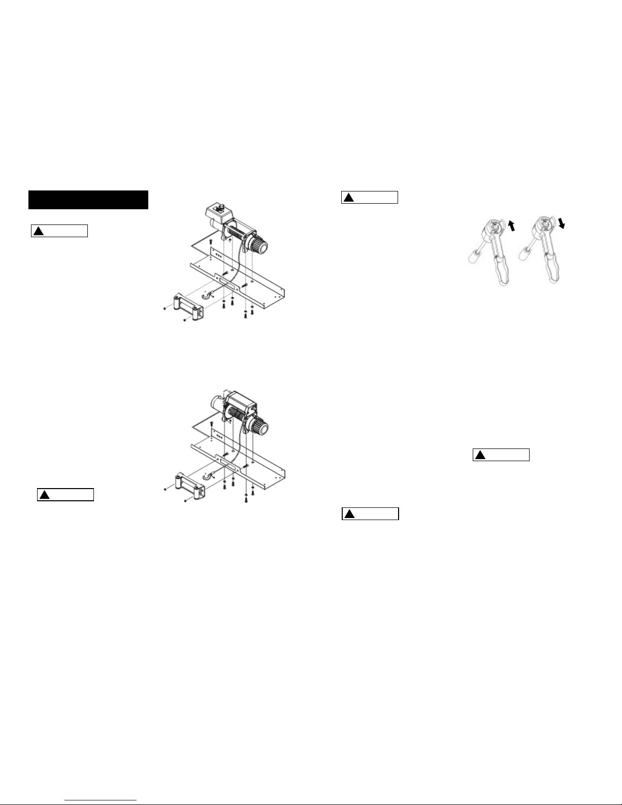
PULLING OUT THE WIRE ROPE
The wire rope has been installed on
your winch under minimal load at
the factory. The wire rope must be
respooled onto the drum under
load so that the outer layers will
not draw down into the inner ones
thereby damaging the wire rope.
Rotate the clutch lever to the “Free
position as shown in Figure 8. If
there is a load on the wire rope, the
clutch lever may not turn easily. DO
NOT FORCE THE CLUTCH LEVER.
Release tension on the wire rope by
jogging out some of the wire rope,
then try releasing the clutch. Pull
out the wire rope and secure to
anchor or load. Check that there
are at least five (5) turns of wire
rope left on the drum. Re-engage
the drum by rotating the clutch
lever to the “Engaged”position
(see Figure 8).
Lever must be in
the engaged
position and locked before winching.
TIPS FOR EXTENDING THE LIFE OF
THE WINCH
1. KEEP A TIGHTLY WOUND WIRE
ROPE DRUM. Do not allow the
wire rope to become loosely
wound. A loosely-wound drum
allows a wire rope under load to
work its way down into the layers
of wire rope on the drum. When
this happens, the wire rope may
become wedged within the body
of the windings damaging the
wire rope. To prevent this prob-
lem, keep the wire rope tightly
and evenly wound on the drum
at all times. A good practice is to
rewind the wire rope under ten-
sion after each use. One way to
do this is to attach the hook to a
stationary object at the top of a
gradual incline and winch your
vehicle up the incline.
2. DO NOT ALLOW WINCH MOTOR
TO OVERHEAT. Remember, the
winch is for intermittent use only.
During long or heavy pulls the
motor will get hot. The internal
parts will be hotter than the case.
To check the motor temperature,
stop winching and carefully touch
the motor case, if the motor is
uncomfortable to touch, allow
the motor to cool before continu-
ing. KEEP THE ENGINE RUNNING
TO RECHARGE THE BATTERY dur-
ing this break.
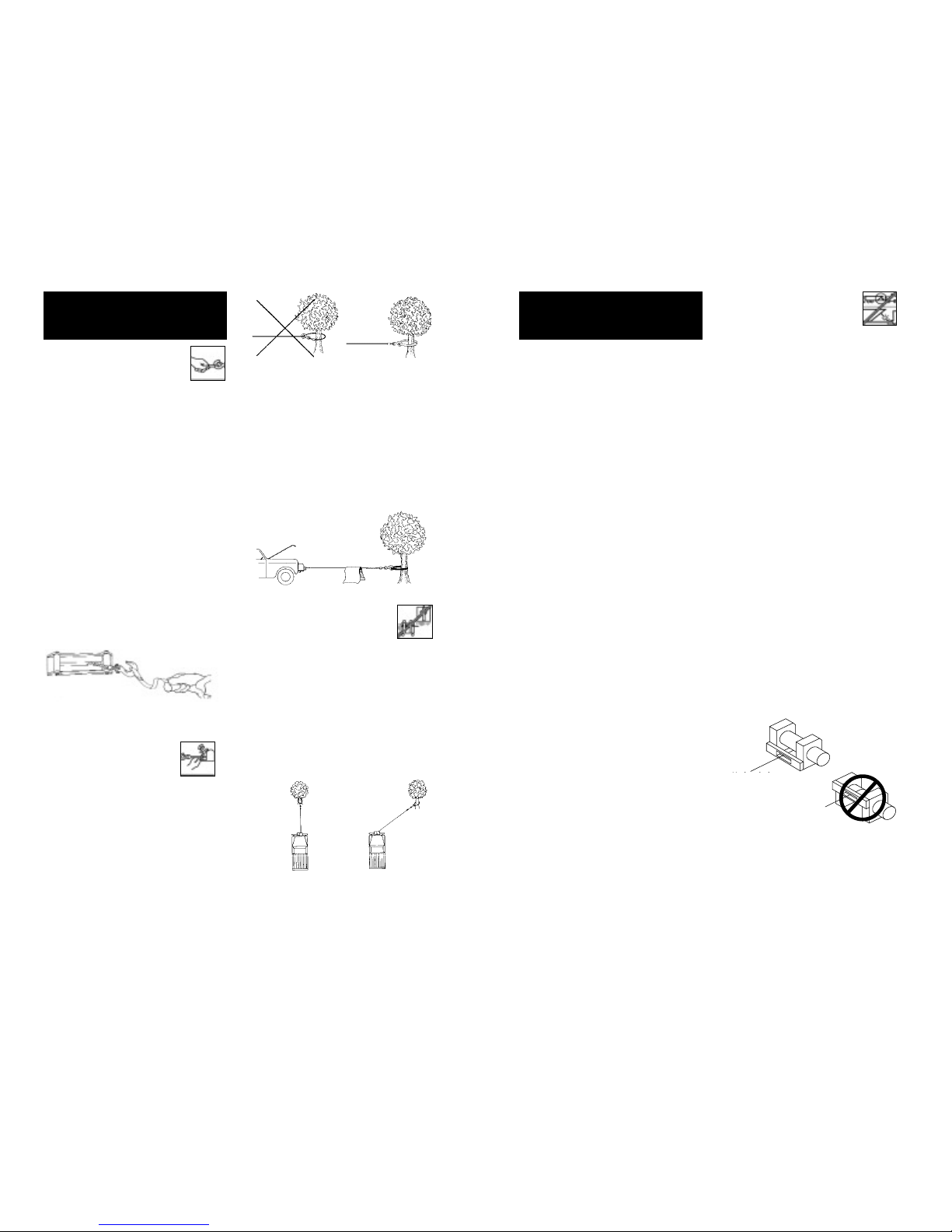
3. To maximize winch and wire rope
life, use a pulley block to double
line heavier loads (Figure 9).
4. The pull required to start a
load moving is often much
greater than the pull required
to keep it moving. AVOID
FREQUENT STOPPING AND
STARTING during pull.
5. PREVENT KINKS BEFORE THEY
OCCUR.
CAUTION
!
10 11
Figure 10
a
b
c
a. This is the start
of a kink. Wire
rope should be
straightened.
b. Wire rope was
pulled and loop
has tightened into
a kink. Wire rope
is now permanent-
ly damaged and
must be replaced.
c. Result of kink-
ing is that each
strand pulls a dif-
ferent amount caus-
ing strands under
greatest tension
to break and
reduce load capac-
ity of wire rope.
The wire rope
must be replaced.
Figure 11
MAINTENANCE
Figure 12
Figure 8
Figure 9

1 12 VDC Motor EP/EPi6.0 90-30500 1
24 VDC Motor EP/EPi6.0 90-30501 1
12 VDC Motor EP/EPi9.0 90-30502 1
24 VDC Motor EP/EPi9.0 90-30503 1
2 Motor Support Rack 90-40500 1
3 Gear Support Rack 90-40501 1
4 Drum Bushing 90-14500 1
5 Drum (3" diameter on 09332 and 09334 only) 90-30517 1
6 Gear Box 90-30504 1
7 Connecting Socket 90-20500 1
8 1st Shaft 90-20501 1
9 1st Pinion 90-20502 1
10 1st Stage Carrier 90-30505 1
11 1st & 2nd Ring Gear 90-30506 1
12 2nd Stage Carrier 90-30507 1
13 3rd Stage Carrier 90-30508 1
14 3rd Ring Gear 90-30509 1
15 3rd Washer 90-20503 1
Freespool Assembly 90-20504
16 Clutch Sleeve
17 Clutch Lever
18 Pressed Spring
19 Clutch Knob
38 Spring Pin
Brake Assembly 90-30510
20 Brake Clutch Base
21 Brake Cam
23 Cone Brake Disc
24 Spiral Spring
25 Brake Cover
27 Bearing
35 C-Rings (2 per assembly)
Hardware Kit 90-14501
29 Hex. Bolt (6 per kit)
30 Hex. Bolt (3 per kit)
31 Hex. Bolt
32 Hex. Bolt
33 Hex. Bolt
26 Bearing 90-20513 1
36 C-Ring 90-14502 1
37 Anit-leak Seal (2 included) 90-20505 1
40 Wire Rope 90-20506 1
41 Roller Fairlead 90-30511 1
42 Mounting Hardware 90-14503 1
43 Clevis Hook 90-20507 1
44 Remote Switch Assembly 90-33450-01 1
45 Handsaver Strap 87-31120 1
46 Snatch Block 90-20508 1
47 Remote Switch Socket 90-25048-01 1
48 Upper Solenoid Box 90-41144 1
49 Solenoid 12V 90-14452 1
Solenoid 24V 90-14454 1
50 Solenoid Mounting Plate 90-24051 1
51 Lower Solenoid Box 90-41145 1
53 Motor Lead Wire Set 90-20511 1
55 Tie Bar 90-20509 1
56 Tie Bar Screw 90-14504 1
57 Spring Washer 90-14505 1
REPLACEMENT
PARTS LIST
Reference
Number Description Part Number Qty
EP SERIES WINCH
ASSEMBLY
Figure 13
12 13
47
49
50
51
53
48
53
18
17
1
46
41
43
37
14
15
13
37
12
10
11
36 21
9
27
23 24
29
33 6
30
35
26 20
16
56
57
4
32
31
38
7
2
4
5
55
19
3
56 57
8
40
42
25
Freespool
Assembly
Brake
Assembly
44
45

REPLACEMENT
PARTS LIST
Reference
Number Description Part Number Qty
EPi SERIES WINCH
ASSEMBLY
14 15
1 12 VDC Motor EP/EPi6.0 90-30500 1
24 VDC Motor EP/EPi6.0 90-30501 1
12 VDC Motor EP/EPi9.0 90-30502 1
24 VDC Motor EP/EPi9.0 90-30503 1
2 Motor Support Rack 90-40500 1
3 Gear Support Rack 90-40501 1
4 Drum Bushing 90-14500 1
5 Drum (3" diameter on 09332 and 09334 only) 90-30517 1
6 Gear Box 90-30504 1
7 Connecting Socket 90-20500 1
8 1st Shaft 90-20501 1
9 1st Pinion 90-20502 1
10 1st Stage Carrier 90-30505 1
11 1st & 2nd Ring Gear 90-30506 1
12 2nd Stage Carrier 90-30507 1
13 3rd Stage Carrier 90-30508 1
14 3rd Ring Gear 90-30509 1
15 3rd Washer 90-20503 1
Freespool Assembly 90-20504
16 Clutch Sleeve
17 Clutch Lever
18 Pressed Spring
19 Clutch Knob
38 Spring Pin
Brake Assembly 90-30510
20 Brake Clutch Base
21 Brake Cam
23 Cone Brake Disc
24 Spiral Spring
25 Brake Cover
27 Bearing
35 C-Ring
Hardware Kit 90-14501
29 Hex. Bolt
30 Hex. Bolt
31 Hex. Bolt
32 Hex. Bolt
33 Hex. Bolt
26 Bearing 90-20513 1
36 C-Ring 90-14502 1
37 Anit-leak Seal (2 included) 90-20505 1
40 Wire Rope 90-20515 1
41 Roller Fairlead 90-30511 1
42 Mounting Hardware 90-14503 1
43 Clevis Hook 90-20507 1
44 Remote Switch Assembly 90-33450-01 1
45 Handsaver Strap 87-31120 1
46 Snatch Block 90-20508 1
47 Control Box Left Cover 90-30512 1
48 Control Box Right Cover 90-30513 1
49 Electric Box 90-30516 1
50 Rubber Clamp 90-20510 1
51 Hex. Bolt 90-14506 1
52 Hex. Bolt 90-14507 1
53 Spring Washer 90-14508 1
54 Solenoid 12V 90-14453 1
Solenoid 24V 90-14455 1
55 Motor Lead Wire Set 90-20512 1
56 Remote Switch Socket 90-25058 1
57 Bolt 90-23032-22 1
58 Nut 90-23149-06 1
59 Rubber Cover 90-25046 1
55
11
10
46
50
12
14
37
1
55
36
9
26
15
13
37
27
17
38
21
24
18
16
19
23
35
20
48
49
34
5
32 47
2
53 52
54
47 51
29
6
33
57
40
42 43
53
52
8
51
59
41
56
58
25
Figure 14
44
30
31
Freespool
Assembly
Brake
Assembly
45

USA
Superwinch Inc.
Winch Drive
Putnam, CT 06260
phone: 860-928-7787
Electric Motor Repair
2010 North 4th Street
Minneapolis, MN 55411
phone: 612-588-4693
Berens & Associates
124 Hegenberger Loop
Oakland, CA 94621
phone: 800-540-2858
Zorko’s Alternator Service
241 Wells Road
Home, PA 15747
phone: 800-468-5055
Electric Motors of Iowa City
50 Commercial Court
Iowa City, IA 52246
phone: 319-354-4040
CANADA
Demand Electric
228-39th St. N.E.
Calgary, AB T2E 2M5
403-230-2709
Harold Supply
3 Southerland Ave.
Sudbury, Ont. P3C 3A7
705-761-4455
Explora Industries Ltd.
9605-5th Ave.
Edmonton, AB T6E 0B2
780-430-8591
Dayworth Sales
1 Saunders Rd. Unit 2
Barrie, Ont. 9A7 9A7
705-726-7778
Les Equipment Twin
10401 Parkway Blvd.
Ville D’Anjou, PQ H1J 1R4
514-353-1190
Buffalo Industries
251-253 Princess Street
Winnipeg, Manitoba R2C 1M1
204-942-1951
Power Plus Tool Repair
57 Millenium Ave.
Moncton, NB E1E 2G2
560-855-8665
Muskoka Auto Parts
11 King William St.
Huntsville, Ont. P1H 2K8
705-789-2321
Lou Dennis Auto
Hiway 11 South
Sundridge, Ont. P0A 1Z0
705-384-5345
Outdoors Plus
128 Regional St.
P.O. Box 1349
Port Aux Basques, NF A0M 1C0
709-695-7533
Bobcaygeon Auto and Marine
91 Main St.
Bobcaygeon, Ont. K0M 1A0
705-738-2317
MAP Bracebridge
19 Taylor Rd.
Bracebridge, Ont. P1L 1W3
705-645-8785
MAP Fenelon Falls
165 Lindsay St.
Fenelon Falls, Ont. K0M 1N0
705-887-6232
Central Electric Motor Rewind
#1-1960 Windsor Rd.
Kelowna, NC V1Y 2Y3
250-860-4415
Delta Tool Repair Limited
114-7533, 135th St.
Surrey, BC V3W 0N6
604-591-3230
Ted's Power Tool Repair
426-44th St. East
Saskatoon, SK S7K OW1
306-934-6155
Bob's Electric Truck Servise
845-B Macdonald Ave.
Regina, SK S4N 2X5
306-721-4148
Off Road Canada
251-12th St. "B" North
Lethbridge, AB T1H 2K8
403-327-7722
Gary's Starter & Alternator
P.O.Box 7 Site 4
RR 1 Mount Uniacke B0N 1Z0
Contact: Gary Thorne
902-757-2388
Power Blitz Mftg. & Maintenance
577 Edgeley Blvd. Unit 6
Concord, Ont. L4K 4B2
905-669-8209
Bruce's Recreaction
92 Balbo Dr.
Shoal Harbour Nfld A5A 4A8
709-466-3355
Atlantic Recreation & Marine
5 School St.
Sydney, Nova Scotia
B1S 3G1
902-567-1697
UNITED KINGDOM
Superwinch, LTD
Abbey Rise, Whitchurch road
Tavistock, Devon PL19 9DR
+44 (0) 1822 614101
WORLDWIDEContact your Local
Superwinch Distributor or callSuperwinch.
TROUBLESHOOTING
CHART
Motor will not operate 1. Damaged or stuck 1. CAUTION: Disengage
or runs in one direction solenoid; most likely clutch before perform-
only caused by not holding ing this test to prevent
the inner nut to keep the powering the wire rope
stud from turning when drum. If a solenoid sticks
attaching wire to solenoid once, it is likely to stick
again and must be
replaced immediately.
Tap solenoid to free
stuck contacts. Check
by applying voltage to
the small solenoid ter-
minal. Be sure solenoid
is grounded back to
source. A solenoid that
is not stuck will make an
audible “click”when first
energized
2. Switch inoperative 2. Replace Switch
3. Broken wires or bad 3. Check for poor connect-
connection tions. CAUTION: Always
use two wrenches
(spanners). (See Figure 10)
4. Damaged motor 4. Replace or repair motor
5. Solenoids not grounded 5. Check the ground path
between battery
negative and solenoid base
Winch will not shut off 1. Solenoid stuck “on”1. If solenoid sticks on,
reverse direction and hold
trigger switch on until the
power lead can be discon-
nected. A safety on-off
switch is available as an
accessory
Motor runs extremely hot 1. Long period of operation 1. Allow to cool
2. Damaged motor 2. Replace or repair motor
3. Damaged brake 3. Replace or repair brake
Motor runs but with 1. Weak battery 1. Recharge or replace
insufficient power or battery. Check charging
line speed system
2. Battery to winch wire 2. Use larger gauge wire
too long
3. Poor battery connection 3. Check battery terminals for
corrosion. Clean as
required
4. Poor ground 4. Check and clean connections
5. Damaged brake 5. Repair or replace brake
Motor runs but drum 1. Clutch not engaged 1. Engage clutch
does not turn
Winch runs backwards 1. Motor wires reversed 1. Recheck wiring
2. Solenoids wired incorrectly 2. Recheck wiring
Will not hold load 1. Excessive load 1. Reduce load or double line
2. Worn or damaged brake 2. Repair or replace brake
Symptom Possible Cause(s) Corrective Action
If a problem arises, contact your nearest
Superwinch dealer or repair center.
16 17
WARRANTY REPAIR CENTERS
Other manuals for EP/EPi6.0
1
This manual suits for next models
1
Table of contents
Other Superwinch Other manuals
Popular Other manuals by other brands

Lutron Electronics
Lutron Electronics DL-9602SD Operation manual

Excalibur
Excalibur XC9946 user guide

Outdoor living today
Outdoor living today 8x8 Gardener's Shed Assembly manual

Mercedes-Benz
Mercedes-Benz TRAVEGO operating instructions

socomec
socomec RESYS M40 operating instructions

Pitsco Education
Pitsco Education Boom-I-Lever Adapter user guide