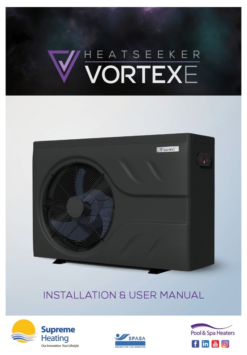
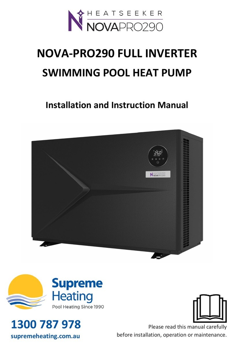
Supreme Heating HEATSEEKER VORTEXPRO Instruction Manual

Heatseeker VortexPro Inverter Heat Pump
Installation & User Manual
1
NATIONAL
INSTALLATION & USER MANUAL

Heatseeker VortexPro Inverter Heat Pump
Installation & User Manual
2supremeheating.com.au
1300 787 978
Head Ofce
Bundoora
VIC 3083
P: (03) 9460 4200
info@supremeheating.com.au
NSW Ofce
Smeaton Grange
NSW 2567
P: (02) 4648 4766
solar.nsw@supremeheating.com.au
salesnsw@supremeheating.com.au
QLD Ofce
Yatala
QLD 4207
M: 0455 064 765
solarqld@supremeheating.com.au
SA Ofce
Wingeld
SA 5013
M: 0437 947 375
solarsa@supremeheating.com.au
WA Ofce
Perth
WA 6000
M: 0447 876 786
darren@supremeheating.com.au
solar@supremeheating.com.au

INSTALLATION & USER MANUAL
HEATSEEKER VORTEXPRO INVERTER HEAT PUMP
Published October 2018
FOR USERS
1. General information 02
1.1. Contents 02
1.2. Operating conditions and range 02
1.3. Advantages of different modes 02
1.4. Kind reminder 03
2. Operations 06
2.1. Notice before using 06
2.2. Operation instructions 06
2.3. Daily maintenance and winterizing 08
3. Technical specication 09
FOR INSTALLERS AND PROFESSIONALS
4. Transportation 10
5. Installation and maintenance 11
5.1. Notice before installation 11
5.2. Installation instructions 12
5.3. Trial after installation 18
6. Vortex Switch 20
6.1. Operation 20
6.2. Heating Priority 20
6.3. Installation Instructions 21
7. Trouble shooting for common faults 22
8. Error codes 23
9. Warranty Agreement 24
Heatseeker VortexPro Inverter Heat Pump
Installation & User Manual
01

1. GENERAL INFORMATION
1.1. CONTENTS:
After unpacking, please check that you have all the following components.
1.2. OPERATING CONDITIONS AND RANGE
ITEMS RANGE
Operating Range Air temperature -7°C - 43°C
Temperature Setting Heating 18°C - 40°C
Cooling 12°C - 35°C
The heat pump will have ideal performance in the operation range Air 15°C - 25°C
1.3. ADVANTAGES OF DIFFERENT MODES
The heat pump has two modes: Smart and Silence. They have different advantages under different
conditions
MODE RECOMMENDATION ADVANTAGES
Smart mode
As standard
Heating capacity: 20% to 100% capacity
Intelligent optimisation
Fast heating
Silence mode
Use at night
Heating capacity: 20% to 80% capacity
Sound level: 3dB (A) lower than Smart mode.
Heatseeker VortexPro Inverter Heat Pump
Installation & User Manual
02

1.4. KIND REMINDER
ATTENTION
This heat pump has power-off memory function. When the power is recovered, the heat
pump will restart automatically.
1.4.1. The heat pump can only be used with pool water. It can NEVER be used to heat or cool other
ammable or turbid liquid.
1.4.2. When moving the heat pump, do not lift the water union. This will damage the titanium heat
exchanger.
1.4.3. Do not obstruct the air inlet or outlet of the heat pump.
Heatseeker VortexPro Inverter Heat Pump
Installation & User Manual
03

1.4.4. Do not obstruct or insert any objects into inlet or outlet of the heat pump. The efciency may
be reduced or even stopped.
1.4.5. To avoid re hazards, do not store or use combustible gas or liquids such as thinners, paints
or fuels near the heat pump.
1.4.6. If you detect any abnormal noises, odours, smoke or leaks from the heat pump, immediately
switch off the power supply and contact your local dealer. Do not attempt to repair the heat
pump yourself.
Heatseeker VortexPro Inverter Heat Pump
Installation & User Manual
04

1.4.7. The main power supply switch should be out of the reach of children.
1.4.8. Please disconnect the heat pump from the power supply during electrical storms.
1.4.9. Please note that following codes are not failures.
CODES
No water ow
Anti-freezing reminder
Out of the operating range
Insufcient water ow or pump blocked
Power abnormal
Heatseeker VortexPro Inverter Heat Pump
Installation & User Manual
05

2. OPERATIONS
2.1. NOTICE BEFORE USING
1. To optimise the life-cycle of the system,
the user is advised to start the water
pump before the heat pump, and turn off
the heat pump before the water pump.
2. Check for any water leakage in connecting
pipework, then turn on the power supply,
press the ON/OFF button of the heat
pump, and set desired temperature.
2.2. OPERATION INSTRUCTIONS
SYMBOL DESIGNATION OPERATION
Power ON/OFF Press to power on or off the heat pump
Up/ Down Press to set desired water temperature
Heat/Cool/Auto Press to switch between cooling, heating and auto
Fan Press to select Silence mode ON/OFF
Note:
1. You can set the desired water temperature from 12°C to 40°C.
2. The numbers on the right of the display show the inlet water temperature. The numbers on
the left of the display show the outlet water temperature.
3. Turn on the heat pump and the fan will start to run after 3 minutes. In another 30 seconds,
the compressor will start to run.
�C�C
MIN
Heatseeker VortexPro Inverter Heat Pump
Installation & User Manual
06

2.2.1 Status on the display
Auto
Mode
Defrost
Mode
Heating
Mode
Cooling
Mode
Timer
ON/OFF
2.2.2. Clock setting
1. Press
for 5 seconds to enter the clock setting. 88:88 is ashing on the display
2. Press or to adjust the time (fast adjusting by continuous pressing). Then, press to
conrm and exit.
3. If no settings are made within 30 seconds, any changes will be lost and the controller will exit
the clock setting.
2.2.3. Timer on and off
1. Press the for 10 seconds to enter the timer setting. The “ON” will be ashing to enter the
Timer ON setting. Press the or to adjust Timer ON time. You can choose Timer ON
(Display: ON), or Repeat Timer ON (Display: 1 ON) by pressing . Then press to conrm.
2. When the “ON” stops ashing, and “OFF” is ashing, you enter the Timer OFF mode. Press the
or to adjust Timer OFF time. You can choose Timer OFF (Display: OFF), or Repeat Timer
OFF (Display: 2 OFF) by pressing . Then press to conrm.
3. After entering the Timer ON/OFF setting, press directly without adjusting the time to
cancel the relevant Timer setting.
4. If no settings are made within 30 seconds, any changes will be lost and the controller will exit
the Timer ON/OFF setting.
2.2.4 Silence mode
1. The Smart mode as default will be activated when the machine is turned on. And the display
shows .
2. When machine is on, press button to enter the Silence mode. will be light. Press
again to exit.
2.2.5 Compulsory defrost
1. When the machine is on heating mode and the compressor is working continuously for
10 minutes, press both and buttons for 5 seconds to start compulsory defrost.
(Note: the break between compulsory defrost needs to be more than 30 minutes.)
2. The defrost symbol is on when machine is in compulsory defrost mode or auto defrost mode.
3. Compulsory defrost will take the same amount of time as auto defrost.
Heatseeker VortexPro Inverter Heat Pump
Installation & User Manual
07

2.3. DAILY MAINTENANCE AND WINTERIZING
2.3.1. Daily Maintenance
ATTENTION
Please don’t forget to cut off power supply to the heat pump
1. Please clean the evaporator with household detergents or clean water. NEVER use gasoline,
thinners or any similar fuel.
2. Check bolts, cables and connections regularly.
2.3.2. Winterizing - Sub-Zero Climates
In climates where the winter season reaches sub-zero temperatures, please disconnect from power
supply and drain water out of the heat pump. When using the heat pump under 2°C, make sure
there is always water ow.
Unscrew the water union of inlet
pipe to let the water flow out.
When the water in machine freezes
in winter season, the titanium heat
exchanger may be damaged.
Heatseeker VortexPro Inverter Heat Pump
Installation & User Manual
08

3. TECHNICAL SPECIFICATION
SPECIFICATIONS THREE PHASE
MODEL 10 KW 13 KW 17 KW 21 KW 28 KW 28 KW 35 KW
Mode Type Heat & Cool
Discharge Side
Fan Quantity 1
Performance at Air 26°C, Water 26°C, Humidity 80%
Heat Capacity kW 9.8 13.3 17.3 21 27.3 27 35.2
COP 6.9-15.3 6.4-15.4 5.9-15.5 5.7-15.2 6.2-15.3 6.2-15.2 5.5-15.5
Performance at Air 15°C, Water 26°C, Humidity 70%
Heat Capacity kW 6.8 9.4 11.4 14.3 18 18 24
COP 4.6-7.7 4.4-7.8 4.3-7.8 4.2-7.7 4.6-8.1 4.5-7.9 4.5-8.0
General
Rated input power
at air 15°C kW 0.21-1.4 0.27-2.1 0.3-2.6 0.36-3.3 0.53-3.8 0.53-3.9 0.63-5.15
Rated input current
at air 15°C Amps 0.91-6.1 1.17-9.1 1.3-11.3 1.57-14.3 2.3-16.5 0.76-5.6 0.91-7.4
Circuit Breaker Amps 10 15 20 25 25 10 15
Power Supply 240v / 50Hz / 1PH 380v / 50Hz / 3PH
Wiring Pre-wired for
10 amp plug Must be hard wired
Pool Volume
- Cold Climate Litres ≤20,000 ≤30,000 ≤40,000 ≤50,000 ≤60,000 ≤60,000 ≤80,000
Pool Volume
- Warm Climate Litres ≤30,000 ≤40,000 ≤50,000 ≤60,000 ≤70,000 ≤70,000 ≤100,000
Advised Flow Rate L/min 60 100 125 150 180 180 230
Inlet / Outlet mm 50
Compressor Twin-rotary Mitsubishi DC inverter
Heat Exchanger Spiral titanium tube in PVC
Casing Black ABS
Noise Level (1m) dBA 38.6-49.9 41.3-54.0 43.1-53.8 40.9-54.2 43.5-54.9 43.5-54.9 42.6-54.7
Refrigerant R410A
Weight / Dimensions
Net Weight kg 49 52 63 68 90 93 117
Net Dimensions
L x W x H mm 961 x 340 x
658
961 x 340 x
658
961 x 420 x
658
961 x 420
x 758
1092 x 420
x 958
1092 x 420
x 958
1161 x 530 x
958
The sizing of heat pumps are based on pool volume for seasonal swimming with the use of a Heatseeker Diamond Pool Cover.
1. The values indicated are valid under ideal conditions: Pool covered with an isothermal cover.
2. Related parameters are subject to adjustment periodically for technical improvement without
further notice. For details please refer to nameplate.
Heatseeker VortexPro Inverter Heat Pump
Installation & User Manual
09

4. TRANSPORTATION
4.1. When storing or moving the heat pump, please ensure the unit remains in an upright position
at all times.
4.2. When moving the heat pump, do not lift the water union. This will damage the titanium heat
exchanger.
Heatseeker VortexPro Inverter Heat Pump
Installation & User Manual
10

5. INSTALLATION AND MAINTENANCE
ATTENTION
It is strongly advised that the heat pump is installed by a professional. Unqualied
installations may result in damage to the heat pump and/or safety risks to the user.
5.1. NOTICE BEFORE INSTALLATION
5.1.1. Plumbing connections must be made with solid PVC pipe. Usage of exible PVC pipe is not
recommended.
Heatseeker VortexPro Inverter Heat Pump
Installation & User Manual
11

5.2. INSTALLATION INSTRUCTION
5.2.1. Location and size
ATTENTION
The heat pump should be installed in a place with good ventilation.
The heat pump is usually installed within a perimeter area extending 7.5m from the swimming
pool. The greater the distance from the pool, the greater the heat loss in the pipes. As the
pipes are mostly underground, the heat loss is low for distances up to 30m (15m from and to
the heat pump; 30m in total) unless the ground is wet or the groundwater level is high. A rough
estimate of the heat loss per 30m is 0.6 kWh (2,000 BTU) for every 5°C difference between
the water temperature in the pool and the temperature of the soil surrounding the pipe. This
increases the operating time by 3% to 5%.
Do not obstruct the air inlet or outlet of the heat pump. The efciency may be reduced or even stopped.
Side Discharge
2500mm
From Front
Discharge
800mm
From Sides
400mm
From Back
500mm
From Top
Heatseeker VortexPro Inverter Heat Pump
Installation & User Manual
12

Check Valve Installation
ATTENTION
Automatic Dosing
Sanitation and automatic dosing systems must be plumbed after the heat pump. A check
valve must be installed between the sanitation/automatic dosing system and the heat
pump to prevent chemicals returning to the heat pump. Failure to observe this instruction
will void the warranty.
Independent System
FROM POOL
TO POOL
3 WAY
VALVE
NON RETURN
VALVE
HEAT PUMP - BACK
OUT
IN
SOLAR PUMP
In-line System
FROM POOL
TO POOL
3 WAY
VALVE
NON RETURN
VALVE
CHLORINATOR
FILTER PUMP
FILTER
OUT
HEAT PUMP - BACK
IN
Heatseeker VortexPro Inverter Heat Pump
Installation & User Manual
13

Adjusting the Bypass
A
B
HEAT PUMP - BACK
FILTER
FILTER PUMP
FROM POOL
TO POOL
3 WAY
VALVE
CHLORINATOR
NON RETURN
VALVE
OUT
IN
Heatseeker VortexPro Inverter Heat Pump
Installation & User Manual
14

Use the following procedure to adjust the bypass:
1. Close the valve to Position A
2. Turn on the circulation pump
3. Slowly open the valve towards Position B until the display error code of “E6” disappears.
Once the message clears, the default display is the current water temperature. Starting
sequence will now begin.
Optimal operation and water ow through the heat pump occurs when the cooling gas pressure is
22 ±2 bar.
This pressure can be read on the pressure gauge next to the heat pump control panel.
ATTENTION
Bypass Installation
Operation without a bypass or with improper bypass adjustment may result in suboptimal
heat pump operation and possible damage to the heat pump. Failure to observe this
instruction will void the warranty.
Heatseeker VortexPro Inverter Heat Pump
Installation & User Manual
15

A B C D E F G H
10 kW 315 590 312 340 961 280 74 658
13 kW 315 590 312 340 961 340 74 658
17 kW 395 590 392 420 961 390 74 658
21 kW 395 590 392 420 961 460 74 758
28 kW 395 720 392 420 1092 620 74 958
28 kW (Three Phase) 395 720 392 420 1092 620 74 958
35 kW (Three Phase) 505 790 496 530 1161 650 74 958
NAME
SIZE (MM)
MODEL
Above data is subject to modication without notice.
5.2.2. Heat pump installation
1. When the heat pump is running, condensation will occur and drain from the bottom of the
unit. This is completely normal. However, consideration should be made for how to drain the
condensation away. Drainage nozzle and pipe are supplied.
Heatseeker VortexPro Inverter Heat Pump
Installation & User Manual
16

5.2.3. Wiring & protecting devices and cable specication
1. Connect to appropriate power supply. The voltage should comply with the rated voltage of
the unit.
2. Earth the machine well.
3. Wiring must be handled by a professional technician according to the circuit diagram.
4. Set leakage protector according to the local code for wiring (leakage operating current ≤ 30mA).
5. The layout of power cable and signal cable should be orderly and not affect each other.
ATTENTION
Switch on after nishing all wiring construction and re-checking.
1. Wiring Diagram
A. For power supply: 240V 50Hz
Distribution Box (Customer prepare)
Power Cord
Swimming Pool Heat Pump Wiring Board
Power Supply
240V 50Hz Breaker
Earthing
Fuse
B. For power supply: 380V 50Hz
Power Cord Swimming Pool Heat Pump Wiring Board
Power Supply
380V 50Hz
Breaker
Earthing
Fuse
Distribution Box (Customer prepare)
R
S
T
N
R
S
T
N
ATTENTION
For the detailed wiring diagram, please refer to Appendix 1.
Heatseeker VortexPro Inverter Heat Pump
Installation & User Manual
17

2. Options for protecting devices and cable specication
MODEL 10 KW 13 KW 17 KW 21 KW 28 KW 28 KW 35 KW
SINGLE PHASE THREE PHASE
Breaker Minimum Rated Current A 15.0 15.0 20.0 25.0 25.0 10.0 15.0
Rated Residual Action Current mA 30 30 30 30 30 30 30
Fuse A 15.0 15.0 20.0 25.0 25.0 10.0 15.0
Power Cord (mm2)3×2.5 3×2.5 3×2.5 3×4 3×6 5×2.5 5×2.5
Signal cable (mm2)3×0.5 3×0.5 3×0.5 3×0.5 3×0.5 3×0.5 3×0.5
NOTE: The above data is adapted to power cord ≤ 10m .If power cord is >10m, wire diameter must be increased.
The signal cable can be extended to 50m at most.
5.3. TRIAL AFTER INSTALLATION
ATTENTION
Please check all the wirings carefully before turning on the heat pump.
5.3.1 Inspection before use
1. Check installation of the whole heat pump and the pipe connections according to the pipe
connecting drawing;
2. Check the electric wiring according to the electrical wiring diagram and earthing connection;
3. Make sure that the main power is well connected;
4. Check if there is any obstacle in front of the air inlet and outlet of the heat pump
Heatseeker VortexPro Inverter Heat Pump
Installation & User Manual
18
Table of contents
Other Supreme Heating Heat Pump manuals

Supreme Heating
Supreme Heating Nova User manual

Supreme Heating
Supreme Heating HEATSEEKER VORTEXE Instruction Manual

Supreme Heating
Supreme Heating Heatseeker NovaS Instruction Manual

Supreme Heating
Supreme Heating NOVA-PRO290 Quick guide

Supreme Heating
Supreme Heating HEATSEEKER VORTEXPRO 10 KW Instruction Manual
Supreme Heating
Supreme Heating Heatseeker Nova+ Programming manual
Popular Heat Pump manuals by other brands

LG
LG MULTI F Series installation manual

York
York YZF024THRU 060*C Technical guide

Mitsubishi Electric
Mitsubishi Electric CITY MULTI PQHY- P216TSLMU-A1 quick start guide

AERMEC
AERMEC Omnia UL PC Use and installation manual

Daikin
Daikin ETVH12S18E 6V Series Operation manual

Carrier
Carrier COMFORT 50EZ-A Product data