SUR-RON Light Bee User manual

!!
SUR-RON LIGHT BEE QL3000DY-2
SERVICE MANUAL

1. Brief Introduction
1.1Safety warning
Do reading the chapter carefully before the repair & maintenance
This service manual is used to guide professional technicians. Please don’t do the repair
and maintenance with the content in this manual neither you take necessary training nor
have any operation experience.
The operations in this manual can only be done in suitable maintenance workshop.
Ensure all essential tools are well prepared before the repair and maintenance.
The power source of LIGHT BEE must be cut off before any operation on the bike. The
failure to cut off its power source may cause serious injury and even death through
electric shock or disassembly and assembly of parts.
When you do the repair and maintenance, please do wear the safety equipment (working
jacket and working boots etc.) in case of burning, cutting, collision or other accidents.
And use protective goggle or gloves if necessary.
Chongqing Qiulong Technology Co., Ltd (Hereafter called Sur-Ron) has the power
of interpretation for all information in the manual. Sur-Ron aimed to build the best
electric bike in the world, therefore, any improvements, which can make the bike have
better performance and quality, Sur-Ron will keep doing improvements(upgrade data of
specific parts design, material,surface coating and technique detail etc. will not be
provided.)Sur-Ron might discontinue or optimize a certain model to adapt to the local
regulations on specific market. If any content missed in this manual, or the bike you got
is different from the description of this manual, please ask the local importer or dealer
for help before you do the repair and maintenance.
1. Brief Introduction
1.1. Safety warning
1.2. Use of the manual
1.3. Disclaimer
2. Technical specification
2.1 Bike parameters

2.2 Torque specifications of important screws
2.3 The top speeds under different battery capacities
2.4 Bike composition
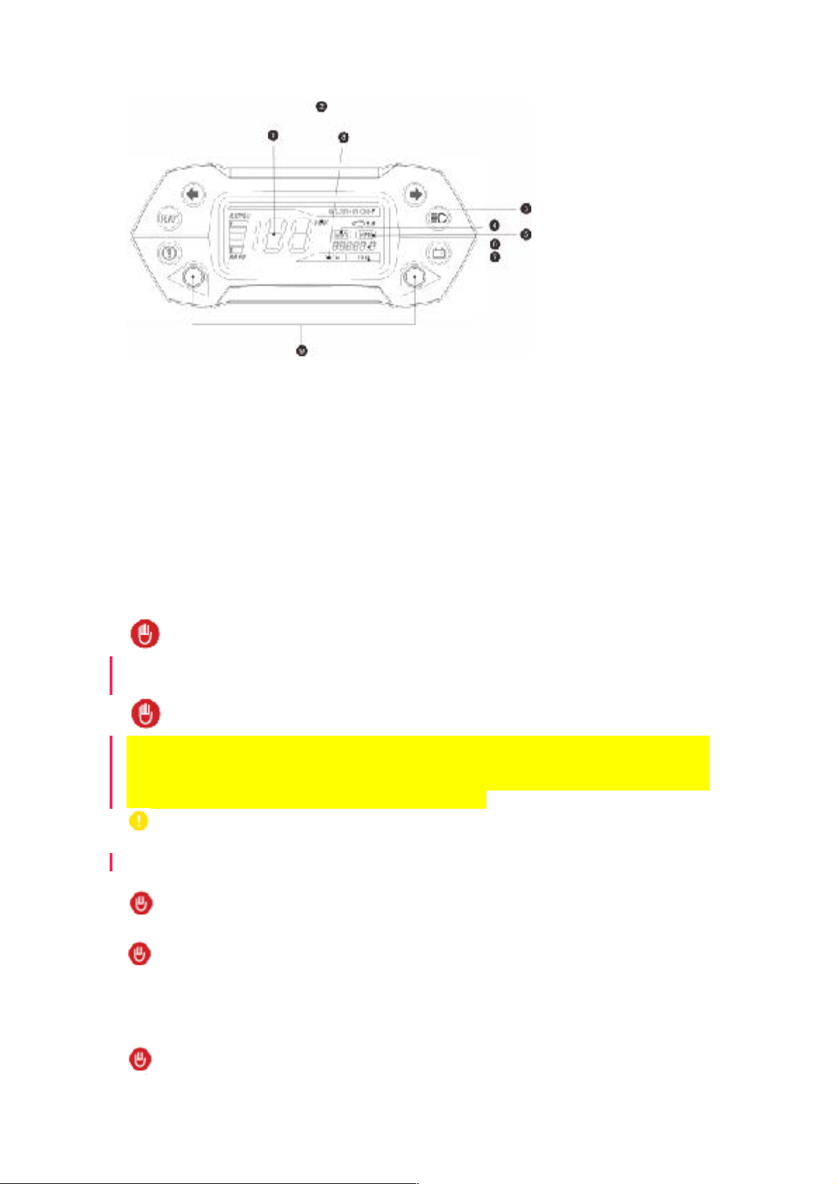
3. Bike operation
4. LIGHT BEE repair tools and preparation work
4.1. LIGHT BEE repair tools
4.2. LIGHT BEE fixing
5. Battery dismount and mount
6. Absorber dismount, mount, and adjustment
6.1 Adjust the compression damping of front absorber
6.2 Adjust setting of absorber
6.3 Absorber lubricating
6.4 Front absorber dismount and mount
6.5 Rear absorber dismount and mount
6.6 Disassembly of rear absorber
7. Check, dismount, mount of the headset
7.1 Check stroke gap of headset
7.2 Disassemble the headset
8. Disassemble and assemble handle bar assembly
9. Wheel checking
9.1 Tire checking
9.2 Rim checking
10. Braking system checking and maintenance
10.1 Brake checking
10.2 Maintenance
10.3 Brake lever dismount and mount
10.4 Brake pump dismount and mount
10.5 Brake clipper dismount and mount
10.6 Brake clipper adopter dismount and mount
10.7 Front brake assembly dismount and mount
10.8 Rear brake assembly dismount and mount
11. Bike body dissemble and assemble
11.1 Mid. Bushing dismounting and mounting
11.2 Motor side-cover dismounting and mounting
11.3 Motor side-cover dismounting
11.4 Disassemble and assemble first level transmission belt
11.5 Disassemble and assemble left pedal assembly
11.6 Disassemble left pedal assembly
11.7 Disassemble and assemble right pedal assembly
11.8 Disassemble pedal assembly
11.9 Disassemble and assemble guard plate under DC motor
11.10 Disassemble and assemble guard plate under controller
11.11 Disassemble and assemble air circuit breaker combination
11.12 Disassemble air circuit breaker combination
11.13 Disassemble and assemble USB and electric control lock combination
11.14 Disassemble USB and electric control lock
11.15 Disassemble and assemble DC motor assembly
11.16 Disassemble and assemble tailstock assembly
11.17 Disassemble tailstock assembly
11.18 Disassemble and assemble left and right limited block of battery
11.19 Disassemble and assemble horn
11.20 Disassemble and assemble back shield
11.21 Disassemble and assemble rear wheel assembly

11.22 Disassemble rear wheel
11.23 Disassemble and assemble rear fork
11.24 Disassemble rear fork
11.25 Disassemble rear fender assembly
11.26 Disassemble rear and inner fender
11.27 Disassemble and assemble cover of battery compartment
11.28 Disassemble and assemble lower stop plate of battery
11.29 Disassemble lower stop plate of battery
12. Checking and maintenance of speed regulation control and brake control device
12.1 Check brake
12.2 Check accelerator
12.3 Confirm power supply control
13. Position adjustment
13.1 Adjust handlebar
13.2 Adjust brake handle
14. Disassembly
14.1 Dismount handlebar of accelerator
14.2 Dismount handlebar
14.3 Dismount throttle bracket
15. Transmission gear
15.1 Check chain and chain wheel
15.2 Clean and lubricate chain
15.3 Disassemble and assemble chain
16. Electric system
16.1 Electric system drawing
16.1 Check electric system
17. The use and maintenance of battery
17.1 Disassembly and assembly of battery
17.2 Maintenance and storage of battery
17.3 Battery charging
18. Checking and maintenance of controller
18.1 Disassembly and assembly of controller
18.2 Checking of controller
19. Electrical failure checking and removal
20. Failure diagnosis

1.2 Use of the manual
!The symbol represents the dangers the bike may cause or other dangerous
situations.
!The symbol represents the dangers which may cause serious physical injuries.
!The symbol represents the potential dangers which can cause harm to health.
1.3 Disclaimer
Modification of the bike may cause physical injuries.
The modification of the bike without approval from Chongqing Qiulong Technology Co.,
Ltd. will lead to the following results:
• Loss of warranty.
• Needs different type of driving license.
• Accidents and serious injuries.
Please read local provisions about electrombile and motor vehicle before using Light Bee
bike.
!According to the certification of L1e-B electric moped scooter that Sur-
Ron Light Bee has passed, its highest speed is 45km/h, so it is not allowed on
expressway or the road segment with the minimum speed of more than
45km/h.
If you have any question, please contact official dealer of Chongqing Surron Technology
Co., Ltd.
The applicable laws require you to provide the following information:
•Your age.
•The equipment necessary for special route.
•Special license for the bike.
•The area with restrictions on vehicles.

2.Technical specification
2.1Bike parameters
Electromotor
type
Brushless DC motor (maximum power 4.0W)
PMAC radial flow brushless, air-cooled and integrated rotate
speed and temperature sensor.
control unit
AC/DC three-phase control unit (maximum power 60V-80A); two
available driving mode:
SPORT:2 kW ECO:0.9 kW
maximum speed
≤45 km/h
power source
type
high-expanded ternary lithium power battery(60V32AH)
rated capacity
1900wh
charger
The special edition high-performance portable charger for LIGHT
BEE QL3000DY power battery
Power: 600 W
Input: 110V AC or 240V DC (according to local voltage)
Output: 67.2V DC/10A
charging time
(standard)
0%-100% - 3.5 hours
0%-95% - 3 hours
0%-80% - 2 hours
mileage
continuation of
journey
ECO mode (average speed 25km/h)>100km
electromotor
double-stage reduction drive system
bike frame/hanger bracket/brake
bike frame
Double-beam cradle type, lightweight aluminum alloy forge
rear absorber
multi-link central shock-absorb system
stroke of front fork
200mm.
stroke of rear wheel
210mm.
front brake
target at 4-piston hydraulic disk brake, disk 203mm
rear brake
target at 4-piston hydraulic disk brake, disk 203mm
front tire
cross-country 70/100-19
rear tire
cross-country 70/100-19
front wheel disk
Aluminum- 19*1.4
rear wheel disk
Aluminum- 19*1.4

2.2 Torque specification of important screws
front absorber
double-shoulder fully adjustable oil pressure reed inverted front
absorber
rear absorber
multi-link fully adjustable damping single-tube air pressure
damping system
size
wheel base
1,230mm
height of vehicle
seat
815 mm
front rake of seat
tube
26°
ground clearance
270 mm
total length
1860 mm
width
780 mm
height
1,050 mm
weight
no battery
42Kg
bike
50 Kg
load capacity
100 Kg
serial
number
item
diameter of thread mm
tightening torque N.m
install left and right lower
controller support
M6
8N•m
fasten front brake disk
M5
8~10N•m
fasten rear brake disk
M6
10~12N•m
fasten rear chainring
M8
20~25N•m
rear absorber, rear rocker arm
connection rod
M8
20~25N•m
fasten bolt of belt wheel
M6
12N•m
fasten bolt of output shaft sprocket
M6
12N•m
fasten nut of front belt wheel
M12
40~50N•m
attachment bracket of left and
right pedals and support of left and
right pedals
M10
40~45N•m
fasten lower battery support plate
M6
8N•m
fasten bolt of connecting plate
M6
10N•m
fasten bolt of bike stem
M5*25
5-6N•m

2.3 The highest speeds under different battery capacities (reference)
2.4 Bike arrangement
2.4.1 Position of bike parts
fasten bolts of bike stem and
handlebar tube
M5
5-6N•m
fasten front wheel axle
M12
20~25N•m
fasten front disk brake
M6
12N•m
fasten back fork shaft
M10
35N•m
fasten auxiliary frame and bike
frame
M8
20N•m
fasten nut of seat cushion
M6
8N•m
rear absorber, bike frame and back
fork
M8
25-30N•m
fasten rear wheel axle
M12
55~60N•m
fasten rear disk brake
M6
12N•m
fasten electrical motor
M8
25N•m
fasten controller and controller
support
M6
8-10N•m
fasten pedal and bike frame
M8
25-30N•m
fasten controller protector bolt
M8
20N•m
serial
numb
er
battery capacity
speed(km/h)
1
100%
42.8
2
90%
42.3
3
80%
41.6
4
70%
40.9
5
60%
40.1
6
50%
39.4
7
40%
38.7
8
30%
37.8

!
Fig 1
1. Rear fender assembly
2. Rear bottom fork
3. Seat cushion
4. Rear absorber
5. Tire
6. Bike frame
7. Three-phase brushless DC motor
8. Ternary power lithium battery
9. Control system
10. Headlight
11. Front absorber
2.3.2 Position of head parts
!
Fig 2
1. LCD Speedometer
2. Front brake handle
3. Rear brake handle
4. Throttle grip
5. Control switch
6. Rear-view mirror
2.3.3 LCD Speedometer functions

!
Fig 3
1.current speed
2.Top speed notice
3.brand logo
4.KMH indication
5.MPH indication
6.Mileage
7.Single trip distance
8.Trip distance in total
9.Buttons for function selections
3. Vehicle operation
This chapter includes all necessary knowledge related to Light Bee operation you need to
learn about:
!
When stop using SUR-RON light bee QL3000DY, cut off main power switch.
Just to move the bike, turn off power switch.
!
If you plan to use the bike after more than 30 days, we suggest you to take
battery down, keep its capacity not less than 50% and charge it at least once
per month. Only the charger and cable equipped for the bike can be used
because they are specially designed for the bike.
!
Only original charger can be used in charging
In order to achieve the best battery performance, charge the bike
immediately after use every time.
!
Full discharge may damage battery
!
The charging and electric power storage not conforming to the instructions in
the manual will invalidate the warranty of battery. These instructions are the
results of strict test and can help to achieve the maximum performance and
longest service life of battery.
!

Cut off air circuit breaker or dismount battery in repair or maintenance of
bike. Hot-line work is not allowed in case of part damage or accidents
3.Repair tools and preparation work (tools can be arranged by yourself or purchased
from Chongqing SUR-RON Technology Co., Ltd.. The special brake mineral oil should be
purchased from Chongqing SUR-RON Technology Co., Ltd.)
4.1 Light Bee’s special repair and maintenance tool kit
1、inner hexagonal spearhead: S3, S4, S5, S6, S10
2、outer hexagonal spearhead: S12, S17
3、Round nut four-claw sleeve: S10
4、cross screw driver
5、AVO meter
6、original special brake mineral oil (LBN)
7、lubricating grease
4.2 Fix Light Bee
In terms of some maintenance operation of Light Bee, we suggest to fix Light Bee
according to the step.
In an open area, turn off power source, open Light Bee’s side stand on floor.

5. Disassemble and assemble battery (see Fig 4)
5.1After turn off power switch, plug key into①battery compartment, then turn key
anticlockwise to open cover of battery compartment②
!
Fig 4
!
Fig 5
Cut off air circuit breaker, power source and disconnect output power line and signal line
of battery③,④
Hold the lifting handle of battery, lift it, then take battery out (see Fig 5)
5.1.1 Assembly
• Assemble battery according to the inverse disassembly steps.
6. Disassemble, assemble and adjust damping system
6.1 Adjust compression damping of front absorber (see Fig 6)
!
Fig 6
The compression damping of front absorber is adjusted through the standard valve core
at the lower right. High-pressure pump is necessary. The recommended pressure is
7-10BAR(100-150 psi).
6.2 Adjust the setting of absorber
6.2.1 Tune front absorber (see Fig 7)
Adjust rebound damping (right absorber)
turn to +
restrain increase (slower)
turn to -

restrain decrease (faster)
preload adjustment (left absorber)
turn to +
increase of spring preload
turn to -
reduction of spring preload
!
Fig 7
6.2.2 Tune rear absorber (see Fig 8)
regulating valve of compression damping force
turn to +, compression pressure increases(harden)
turn to -. compression pressure lowers (soften)
regulating valve of rebound damping force
turn to +, restrain increase (slower)
turn to -, restrain decrease (faster)
!
Fig 8
adjustment of spring preload
turn nut clockwise to increase preload force
turn nut anticlockwise to reduce preload force
6.3 Damping and lubrication
!
Warning: Light Bee QL3000DY absorber is designed for non-detachable, don’t
attempt to open or disassemble absorber.
Don’t disassemble Light Bee QL3000DY’s absorber. Please lubricate absorber according to
the following steps and keep its best state:
•dismount protective cover. (see Fig 9)
•unscrew dustproof ring support and slide it along stanchion
•clean the dust on absorber stanchion (mud and old lubricating oil)
•Apply a layer of special lubricating oil for Light Bee QL3000DY between stanchion fixed
seat of dustproof ring.
•Tighten dustproof ring to keep lubricating oil inside absorber.

!
Fig 9
6.4 Disassemble and assemble front damping system
6.4.1 Disassemble front case and instrument (see Fig 10)
•Dismount bolts of case①②, take down front case and disconnect lamp line
•Dismount bolts of support of front case③④, disconnect instrument line and take down
instrument and support of front case.
6.4.1.1Assembly
• Assemble front damping system according to the inverse disassembly steps and fasten
it with the torque force of 10~12N.m.
!
Fig 10
6.4.2 Disassemble headlight and front turning light (see Fig 11)
.Dismount turning light, install nuts and take down turning light⑤
.dismount bolts of support of front case②and separate headlight and front case①③
.dismount bolts of headlight and separate headlight and front case①④
6.4.2.1 Assembly
• Assemble headlight and turning light according to reverse disassembly steps and fasten
them with the torque force of 10~12N.m.
!
Fig 11
6.4.3 Disassemble front wheel assembly(Fig 12)
• Loosen bolts of wheel and axle of lower support of front absorber①
• Dismount fastening bolts of front wheel and axle, draw wheels and axles out and

dismount front wheel assembly
• Dismount bolts of front fender and lining②and front fender
6.4.3.1 Assembly
• Assemble front wheel assembly according to the inverse disassembly steps, fasten front wheel and
axle with the torque force of 10~12N.m and bolts with the torque fore of 20-30N.m.
!
Notice: it is important to fasten fastening bolts of wheel and axle alternatively
and repeated in order to disperse loads uniformly. Fastening the second bolt
may cause the first bolt loose.
!
Ensure brake disk is between brake pads in assembly of front wheel.
Otherwise, brake lining or brake disk may be damaged.
Fig 12
6.4.4.Dismount front brake disk (Fig 13, 14)
• place front wheel assembly flatwise with disk upwards. Clean and protect it.
• Dismount bolts of front brake disk①, take down front brake disk②and avoid
contaminating brake disk
6.4.4.1 Assembly
• Assemble front brake disk according to the inverse disassembly steps, use thread
locking glue (Loctite 243) on bolt, fasten it with the torque force of 8-10N.m. Pay
attention to rotation and install direction of brake disk, avoid contaminating brake disk,
use absolute ethyl alcohol in cleaning
• Ensure disk is at a correct position (see the following figure)
! ! 图注
Fig 13 Fig 14
6.4.5Dismount front absorber (see Fig 15)
• Dismount bolts of front brake caliper and take down front brake caliper③
• loosen bolts of front stanchion①from front absorber, take down steering limiting rubber
bearing of absorber②, and take down front left and right absorbers

6.4.5.1Assembly
• Assemble front absorber according to the inverse disassembly steps and fasten it with
the torque force of 10~12N.m.
!
Notice: it is important to fasten bolts of absorber alternatively and repeatedly
in order to disperse loads uniformly. Fastening the second bolt can make the
first bolt loose.
!
Fig 15
6.5 Dismount rear absorber and rocker arm (see Fig 16, 17)
Dismount rear absorber according to the following steps:
•Put LIGHT BEE QL3000DY on platform or support plat at bottom bracket area
•Loosen the bolts of connector at the upper part of absorber②: fix rear wheel make
sure it not falls off and dismount bolts. Put the bike on floor.
•Loosen the bolts of connector at the lower part of absorber②
•dismount absorber②
•Dismount bolts of rocker arm and take down connecting rod of rocker arm④and rocker
arm⑤.
6.5.1 Assembly
• Assemble rear absorber and rocker arm according to the inverse disassembly steps.
Fasten M8 bolt of absorber with the torque force of 25-30N.m.
!
Don’t damage the paint on rocker arm and bike frame in disassembly and
assembly of absorber.
! !
Fig 16 17Fig 17

6.6 Disassemble damping spring
Disassemble damping spring according to the following steps:
• Dismount absorber (see “6.5 dismount rear absorber”)
• Unscrew preloaded adjustment nut to loosen spring.
• Dismount gasket of spring seat
• Dismount spring
6.6.1Assembly
• Assemble damping spring according to the inverse disassembly steps.
!
Fig 18
7.Check, disassemble and assemble head parts
7.1Check the stroke gap of head parts
Fig 15
If head parts have gap or steering position has resistance, check the tightness of bolt①
of cover of head parts. The correct torque is 8-10N.m. Before adjusting the bolt, fasten
the two fastening bolts between handlebar and stand pipe②and the fastening bolts on
connecting plate③.
• If necessary, fasten or unscrew bolts. If the recommended torque can’t be achieved by
fastening, star nuts may be damaged. In the case, you must use new head parts.
• If head parts can’t work normally (resistance in steering, gap or overhigh resistance)
after the recommended torque is achieved by tightening, some parts on bearing may be
damaged. In the case, you must use new head parts.
7.2 Disassemble head parts
Disassemble the head parts of Light Bee QL3000DY according to the following steps:
• Put Light Bee QL3000DY on support at bracket area
• Dismount front case and instrument (see “6.4.1 disassemble front case and
instrument). Do not damage instrument connection line.
• Dismount front fender and front wheel (see “6.4.3dismount front wheel assembly”)
• Dismount brake handle (see “separate brake handle from handlebar”)
• Loosen locking bolts between handlebar and stand pipe of steering column (see Fig
16).
• Loosen locking bolts of upper and lower connecting plate of front absorber
• Dismount lower connecting plate and absorber assembly and ensure no parts missing
• Dismount bearing cover of hear parts
• Dismount star nuts. Install nuts inside stand pipe of steering column through pressure.
Use M6 thread rod to push nuts out from above.
!
If any part is damaged when drawing out head parts, install new head parts to
ensure the functional of system.

!
Fig 19
7.2.1 Assembly
• Assemble head parts according to the inverse disassembly steps and with the following
torque values:
!
Important notice: fasten cover of head parts, upper connecting plate and
clamp bolts between handlebar and steering column and locking bolt of
absorber of upper connecting plate successively.
• Fasten upper connecting plate,handlebar and stand pipe of steering column using the
M5 bolt withtorque of 8N.m.
front absorber M16 Locking bolt: 10-12N.m
Use special tool to pass new star nuts through the upper hole of stand pipe of steering
column.
!
Be careful when inserting star nuts. If it is at a deeper position than the
designed depth, locking bolts are not long enough to achieve proper
fastening.
!
Fig 20
8 Disassemble and assemble handlebar assembly (Fig 21)
Disassemble head parts of Light Bee QL3000DY according to the following steps:
• Put Light Bee QL3000DY on support at bracket area
• Dismount left and right rearview mirror
• Dismount handle grips, throttle and switch. Do not damage switch line.
• Dismount upper pump of brake (see “dismount upper pump from handle bar”)
• Dismount locking bolts between handlebar and handlegear tube (see Fig 16), take
handle gear down
8.1.1 Assembly
• Assemble handlebar assembly with the following torque and according to the inverse
disassembly steps:
• Fasten main pump of disk brake and M5 bolts between handlebar and handlebar tube
with the torque of 8-10N.m.

!
Fig 21
9. Check wheel
9.1 Check tire
9.1.1 Tire status
The height of sliding block of mud tire must be checked regularly. The acceptable
minimum height is 2mm. If its height is lower than 2mm, must replace new tire.
9.1.2 Pressure
Tire pressure examination is aimed at cooled tires, so tires should not be used within a
few hours before examination. The recommended pressure for front and rear wheels is
225KPa.
Inappropriate pressure or tire may cause:
-unexpected cracking
-lose control of bike
-low tire pressure causes increased rolling resistance
-reduce service time
-clamping and piercing
9.2 Check wheel rim
Deformation examination for wheel rim should be conducted according to the following
steps:
• Put Light Bee QL3000DY on support at bracket area
• Confirm wheels rotate properly. Check whether wheels swing transversely (see Fig 22).
If swing transversely occurred, measure their transverse motion through indicator. If
transverse motion exceeds 1.5mm, check whether wheel rim is deformed or bearing is
damaged. If wheel rim is in a good condition, check whether tire is installed on wheel
rim correctly.
!
Fig 22
If wheel rim is in normal condition but the wheel rotate surface is not vertical to the
ground (see Fig 23), bottom fork may be bended or installed incorrectly. Check bottom
fork.

!
Fig 23
9.2.1 Tension of spoke of wheel
Ensure the tension of spoke of wheel is normal. Otherwise, bike may become unstable.
Check whether spoke of wheel is tense. If any spoke of wheel is not tense, fasten them
and check status of wheel rim and gap of wheel hub
10. Checking and maintenance of brake system
10.1 Check brake
10.1.1 Power examination
Before use, check whether the power and brake is normal. must feel the brake point. If
there is no brake point at two thirds of stroke of brake handle, press brake handle
repeatedly until it reaches brake disk.
Adjust the contact area of brake handle according to the indications in the following
figure.
If brake point is not found at the starting point of stroke of brake handle, deflate brake
system (see “10.2.1 deflate brake”)
10.1.2 Check the status of flexible brake pipe
Check the length of all flexible brake pipes and accessories connect with brake handle
and callipers to find any potential damage or fluid leakage.
10.1.3 Check brake pad
As shown in Fig 24, the thickness of brake pad is 2.5mm at least (including metal
support). Replace the brake pads if the thickness is less than 2.5mm immediately.
!
Fig 24
10.1.4 Check the thickness of brake disk
As shown in Fig 25, the thickness of brake disk is 1.6mm. Replace the brake disks if the
thickness is less than 1.6mm immediately.
!
Fig 25
10.1.5 Check brake disk
Brake disk must be kept horizontal in order to ensure functional. Bended brake disk will
make braking feeling irregular, worsen power and control of brake and accelerate the
Other manuals for Light Bee
2
Other SUR-RON Scooter manuals