Sure Torque ST-LAB User manual
rev. 08.15.2006. 1-1
Read This First!
TO UNPACK AND SET UP YOUR SURE TORQUE BENCHTOP TORQUE TESTER, PLEASE PERFORM THE
FOLLOWING STEPS:
Tools needed: Screwdriver, Allen wrench set.
1. Carefully remove the crating box cover to expose the machine, which is mounted on the crate’s base. Then using an
Allen wrench set, unscrew four screws in the machine’s base.
2. Next, unscrew the screws holding the machine tight in the crating box then identify the other components and
assembly hardware.
3. Connect the main air supply to the rear air plug (refer to section 2.5.1 in the manual for specifications).
4. Attach the provided CE marked power supply to the rear of the system.
5. Run unit in manual cycle first to check component operation and alignment before running automatic cycle.

rev. 08.15.2006. 1-2
Corporate Overview
Sure Torque (ST) began the development of the first electronic torque tester in 1985 in response to the needs
of manufacturing and quality control engineering departments for precision torque testing instrumentation, capable of
accurate, NIST certifiable torque measurement. Our equipment line offers rigorous testing of closure integrity, and is a
necessary requirement to meet today’s stringent specifications for quality control and data collection.
Our torque testers are currently an invaluable part of the production and quality control departments for major
corporations such as Abbott, Eli Lilly, Schering, Upjohn, Procter & Gamble, Coca Cola, S.C. Johnson, Gerber,
Seagram, Hershey, Warner Lambert, and Kraft General Foods, to name a few.
Container cap torque is important, not only for package appearance and product integrity, but mainly for
customer satisfaction and consumer safety. We fully support a total commitment to quality control at ST; after all, we
developed this advanced technology in response to the needs of our customers. ST continues to respond to our
customers’ needs by developing and manufacturing the most sophisticated, up to date electronic torque testers
available in the world today.
We know today’s consumers judge product quality based on many criteria, which include packaging,
appearance and overall effectiveness of the product. Cap torque not only impacts the package’s appearance, but more
importantly, the customer’s perception of the manufacturers’ level of quality and concern.
In today’s competitive market, the consumer avoids buying products if there is detectable evidence of product
leakage, product tampering or something as simple as a difficult to remove closure.
Quality control of the filling operation is concerned with possible product loss due to loose caps on liquid
products and the stability of both liquid and dry products. Stability is of particular concern with moisture sensitive
products, which require that the integrity of the container cap and the internal seal be maintained. Stability
considerations are critical since product loss due to evaporation or moisture absorption can cause significant changes
in potency and thereby the efficacy of the product.
Container closure application can significantly affect the success of a product and closure application defects
are detectable with the correct torque testing protocols in place, thus assuring closures meet certain specifications,
thereby assuring product integrity.
To achieve the desired level of product quality, manufacturers set certain specifications for acceptable torque
values, based upon container closure testing conducted on each container type.
At ST, our line of torque testing equipment is designed to not only conduct precise closure torque testing, but
to also provide data necessary for evaluation of a closure system’s compatibility to a container, efficiency of tamper
evident bands and closure or liner durability. This data will help determine a closure’s conformance to performance
specifications, and evaluate a capper’s capability.
Our customer service and parts departments are always willing to help you with ordering the proper parts, and
will answer any questions you may have about operation and maintenance of your machine.
ST invites you to attend a guided tour of our manufacturing facility including demonstrations of our laboratory
torque testing equipment. Please feel free to contact ST for information, brochures and specification literature for our
quality, state of the art, precision instrumentation.
Thank you for your interest in Sure Torque
We look forward to supporting your closure testing requirements.
Dan Delzer
President
Sure Torque
2532-34 Trailmate Drive
Sarasota, Florida 34243
Office: (941) 753-1095
Fax: (941) 756-8425
http://www.suretorque.com

rev. 08.15.2006. 1-3
Preface
Thank you for the confidence you have shown in Sure Torque, as demonstrated by your purchase of our
equipment.
Although many machine concepts and subsystem operations may be common to several different Sure Torque
machine models, this Operation and Maintenance Manual (O&M) applies to your specific packaging system.
This manual is intended to provide a comprehensive description of your system’s machine concepts, safety
precautions, operation, basic maintenance, and adjustments necessary to assure optimum performance. A
troubleshooting and replaceable parts section is included (section 5) to aid in prolonging maximum machine
productivity and packaging line “up-time.” We at ST take great pride in you, our customer, and dedicate this manual to
support your goal of prolonged system productivity throughout the years.
ST machines normally require little special attention other than routine lubrication and cleaning. Routine
preventative maintenance procedures, however, should always be followed, especially those recommended in this
manual. In particular, component contact areas should be inspected regularly for proper alignments and for possible
wear or damage. The handy “Replaceable and Spare Parts List” (optional) will aid in rapid replacement of worn, or
damaged parts, and will help return your machine to on-line productivity in the shortest possible time.
It is also extremely important to observe good shop safety practices in all aspects of installation, lubrication,
operation, maintenance, and adjustments of all ST packaging equipment. Safety instructions given in this manual
should be followed strictly, without exception under all circumstances.
If this manual does not answer a particular question, or leaves doubts in the proper operation of your machine, do
not hesitate to contact our Customer Service department in Sarasota, Florida (941) 753-1095.
Your ST representative is eager to help you get the most production possible out of your torque tester. Our staff
can ensure that you receive any additional information you may need. We will work with you in solving interfacing or
mechanical problems, and will guide you in ordering the proper equipment, or replacement parts.
Again, thank you for becoming another loyal ST customer.
Sincerely,
Dan Delzer
President
SURE TORQUE Worldwide Torque Testing Equipment Specialists!

rev. 08.15.2006. 1-4
rev. 08.15.2006. 1-5
Safety Comes First With ST
Throughout this manual, ST will emphasize safety precautions that should be adhered to by all personnel setting
up, operating, maintaining and repairing all ST equipment. Machine and personal safety depends on adherence to ALL
CAUTIONS and WARNINGS. Since actual working environments vary greatly, it is impossible to mention ALL
precautions that should be taken in any particular situation. It is your responsibility to be alert while working with any
machinery. Failure to do so will cause personal injury or equipment damage.
All precautions and warnings should be discussed with All personnel operating, working on, or near any packaging
equipment or production lines.
Follow All Safety Precautions In This Manual
NOTE:
Generally, CAUTION conditions refer to equipment damage, whereas WARNING conditions alert personnel to the
possibility of bodily injury. One hazardous condition, however, could easily cause the other.
WARNING
Personal Injury Or Equipment Damage May Result If The
Following 10 Safety Precautions Are Not Observed At All Times.
1. DO NOT operate any machine until you have completely read the manual.
2. DO NOT operate machine without safety guards in place. Stop the machine if guards are opened.
3. STAY CLEAR of all moving parts, AND NEVER wear baggy clothes around machines. Protect long hair with a
hair net.
4. STOP the machine before clearing container jams.
5. STOP the machine before cleaning.
6. STOP the machine before performing maintenance or lubrication procedures.
7. Disconnect power BEFORE changeovers or adjustments.
8. ENSURE machine is properly grounded.
9. Permit ONLY qualified personnel to open the electrical enclosure.
10. Ensure that All personnel are clear of the machine BEFORE starting.
REMEMBER!
ADHERE TO ALL SAFETY PRECAUTIONS LISTED ABOVE
AND THROUGHOUT THIS MANUAL
SURE TORQUE Worldwide Torque Testing Equipment Specialists!
rev. 08.15.2006. 1-6
Electronic Torque Tester: Model ST-LAB
Operation and Maintenance Manual
With Appendix A containing:
• Machine Tuning Sheet
• Certification Records
• Closure Records
• Top Load Setup Procedure – Optional
• Sure Torque DAQ Software – Optional
• Sure Torque DAQ Plugin Torque-Time/Angle Analysis – Optional
• Instructions for Optional Sure Torque Test Methods – Optional
• Instructions for Decay, Alarm, four level Password Protection,
Adaptive Torque application features – Optional
Information provided in this document contains proprietary data on patented products and systems. This
information is furnished for the exclusive use of the customer to install, maintain, repair, and operate the
equipment covered in a specific purchase agreement. Disclosure of the data contained herein to any individual or
organization not a party to the specific purchase agreement and all other uses, including reproduction by any
means, is strictly prohibited without the express written consent of Sure Torque Acceptance and use of this
manual constitutes acceptance of these terms and conditions.
PREPARED BY:
SURE TORQUE
2532-34 Trailmate Drive
Sarasota, Florida 34243
Tel: (941) 753-1095 Fax: (941) 756-8425
SURE TORQUE Worldwide Torque Testing Equipment Specialists!

rev. 08.15.2006. 1-7
Table of Contents
Read This First!...............................................................................................................................................1-1
Preface.............................................................................................................................................................1-3
Safety Comes First With ST............................................................................................................................1-5
Electronic Torque Tester: Model ST-LAB .....................................................................................................1-6
1. General Information..............................................................................................................................1-10
1.1. System Overview ..........................................................................................................................1-10
1.1.1. Control Interface....................................................................................................................1-10
1.1.2. Mechanical Assembly ...........................................................................................................1-10
1.1.2.1. Stand Assembly.............................................................................................................1-12
1.1.2.2. Chuck Assembly............................................................................................................1-12
1.1.2.3. Change-Parts .................................................................................................................1-12
1.1.2.4. Pneumatic Assembly.....................................................................................................1-12
1.1.3. Electronic Assembly..............................................................................................................1-14
1.1.3.1. Transducer.....................................................................................................................1-14
1.1.3.2. Programmable Logic Controller....................................................................................1-14
1.2. Operational Sequence of the Test Cycle Functions.......................................................................1-14
1.2.1. Clamping Sequence...............................................................................................................1-14
1.2.2. Head Lowering Sequence......................................................................................................1-14
1.2.3. Chuck Actuation Sequence ...................................................................................................1-14
1.2.4. Torque-Test Sequence...........................................................................................................1-14
2. Installation Instructions.........................................................................................................................2-15
2.1. Receiving the Unit.........................................................................................................................2-15
2.1.1. Inspecting ..............................................................................................................................2-15
2.1.2. Unpacking .............................................................................................................................2-15
2.2. Positioning the Unit.......................................................................................................................2-16
2.3. Pre-Run, Sure Torque Check-out..................................................................................................2-16
2.4. Electrical Installation.....................................................................................................................2-16
2.4.1. Precautions ............................................................................................................................2-17
2.4.2. Connections...........................................................................................................................2-17
2.5. Pneumatic Installation...................................................................................................................2-17
2.5.1. Air Supply .............................................................................................................................2-17
2.5.2. Plumbing ...............................................................................................................................2-17
2.5.3. Air Pressure Settings.............................................................................................................2-17
2.6. Machine Tuning Sheet...................................................................................................................2-17
3. Operating Instructions...........................................................................................................................3-18
3.1. Controls and Indicators .................................................................................................................3-18
3.2. Machine Setup...............................................................................................................................3-19
3.2.1. Mechanical Setup..................................................................................................................3-19
3.2.2. Electronic Setup ....................................................................................................................3-20
3.2.2.1. Timer configuration.......................................................................................................3-21
3.2.2.2. Speed Settings ...............................................................................................................3-22
3.2.2.3. Miscellaneous................................................................................................................3-23

rev. 08.15.2006. 1-8
3.2.2.4. Load/Save Presets..........................................................................................................3-24
3.2.2.5. Serial communication, Data table setup........................................................................3-25
3.2.2.6. Unlocking operation modes, optional features..............................................................3-26
3.2.2.7. Alarm settings................................................................................................................3-27
3.2.2.8. Calibration.....................................................................................................................3-28
3.3. Displayed messages, options and instructions. .............................................................................3-30
3.3.1. Display...................................................................................................................................3-30
3.3.2. Power On...............................................................................................................................3-30
3.3.3. The Mode Screens.................................................................................................................3-31
3.3.3.1. Manual Mode ................................................................................................................3-31
3.3.3.2. Applied Mode................................................................................................................3-33
3.3.3.3. Release Mode................................................................................................................3-34
3.3.3.4. Multiple Applied Mode.................................................................................................3-34
3.3.3.5. Applied then Release Mode ..........................................................................................3-35
3.3.3.6. Multiple Release Mode .................................................................................................3-35
3.3.3.7. Release and Applied Mode............................................................................................3-35
3.3.3.8. Reverse Ratchet Mode...................................................................................................3-35
3.3.3.9. Shelling Mode ...............................................................................................................3-35
3.3.3.10. Strip Test .......................................................................................................................3-35
3.3.3.11. Nondestructive Release Mode.......................................................................................3-35
3.3.3.12. Various Dispenser Pump Head Tests............................................................................3-35
3.3.3.13. Sealed closure torque testing methods ..........................................................................3-36
3.3.3.14. Precision Applied and Release tests..............................................................................3-36
3.3.3.15. Topload measurements..................................................................................................3-36
3.3.4. Historical Data Screens.........................................................................................................3-36
3.3.5. Serial Communication...........................................................................................................3-37
3.3.5.1. Sure Torque Data Acquisition.......................................................................................3-37
3.3.5.2. Customisation of the communication string..................................................................3-37
4. Maintenance ..........................................................................................................................................4-38
4.1. Cleaning.........................................................................................................................................4-38
4.2. Preventive Maintenance................................................................................................................4-38
4.3. Pneumatic Maintenance ................................................................................................................4-39
4.3.1. Air Leaks...............................................................................................................................4-39
4.3.2. Air Filter................................................................................................................................4-40
4.3.3. Solenoid Valves.....................................................................................................................4-40
5. Troubleshooting Guide..........................................................................................................................5-41
6. Sure Torque Warranty, Limitation of Liability and Service Information.............................................6-43
7. Sure Torque Options List......................................................................................................................7-44
7.1. Software Mode List.......................................................................................................................7-44
7.1.1. Release Mode........................................................................................................................7-44
7.1.2. Applied Torque Mode...........................................................................................................7-44
7.1.3. Multiple Applied Mode.........................................................................................................7-44
7.1.4. Applied then Release Torque Mode......................................................................................7-44
7.1.5. Release then Re-Apply Mode................................................................................................7-44
7.1.6. Non-Destructive Release Mode.............................................................................................7-44

rev. 08.15.2006. 1-9
7.1.7. Non-Destructive Release and Re-Apply Mode.....................................................................7-45
7.1.8. Repetitive Applied then Release (Fatigue) Mode .................................................................7-45
7.1.9. Multiple Peak Mode..............................................................................................................7-45
7.1.10. Reverse Ratchet Mode...........................................................................................................7-45
7.1.11. Shelling Fixture Mode...........................................................................................................7-45
7.1.12. Strip Test ...............................................................................................................................7-45
7.1.13. Various Dispenser Pump Head Tests....................................................................................7-45
7.1.14. Sealed closure torque testing methods ..................................................................................7-45
7.1.15. Precision Applied and Release tests......................................................................................7-45
7.1.16. Topload measurements..........................................................................................................7-46
7.2. Other Options list..........................................................................................................................7-46
7.2.1. 360°/720° Degree Test Mechanism.......................................................................................7-46
7.2.2. Metric/US Measurement .......................................................................................................7-46
7.2.3. RS-232 Interface....................................................................................................................7-46
7.2.4. Real Time Clock (RS-232 serial port required) ....................................................................7-46
7.2.5. Verification Kits....................................................................................................................7-47
7.2.6. STDA Software.....................................................................................................................7-47
7.2.7. Password Protection Feature.................................................................................................7-47
7.2.8. Time Decay Feature..............................................................................................................7-47
7.2.9. Historical Data Option...........................................................................................................7-47
8. Glossary.................................................................................................................................................8-48
9. Data Acquisition Program for the ST-LAB Bench Top Torque Tester................................................9-51
9.1. General ..........................................................................................................................................9-51
9.2. System Requirements....................................................................................................................9-51
9.3. Installation.....................................................................................................................................9-51
9.3.1. Hardware Installation............................................................................................................9-51
9.3.2. Software Installation..............................................................................................................9-51
9.4. Operation.......................................................................................................................................9-51
SURE TORQUE Worldwide Torque Testing Equipment Specialists!

rev. 08.15.2006. 1-10
1. General Information
Sure Torque recommends that all operators and service personnel scan the Table of Contents to familiarize
themselves with the contents and layout of this technical manual. Since certain modifications have been made or
requested by our customers, this is a general guide and all of the technical information in this manual may not pertain
to your specific machine. Changes in machine design or specifications are a result of continual machine improvement
and Sure Torque reserves the right to change specifications without prior notice.
The following chapter gives a brief description of the operational philosophy of your fully automated ST-LAB, Sure
Torque Electronic Torque Tester System.
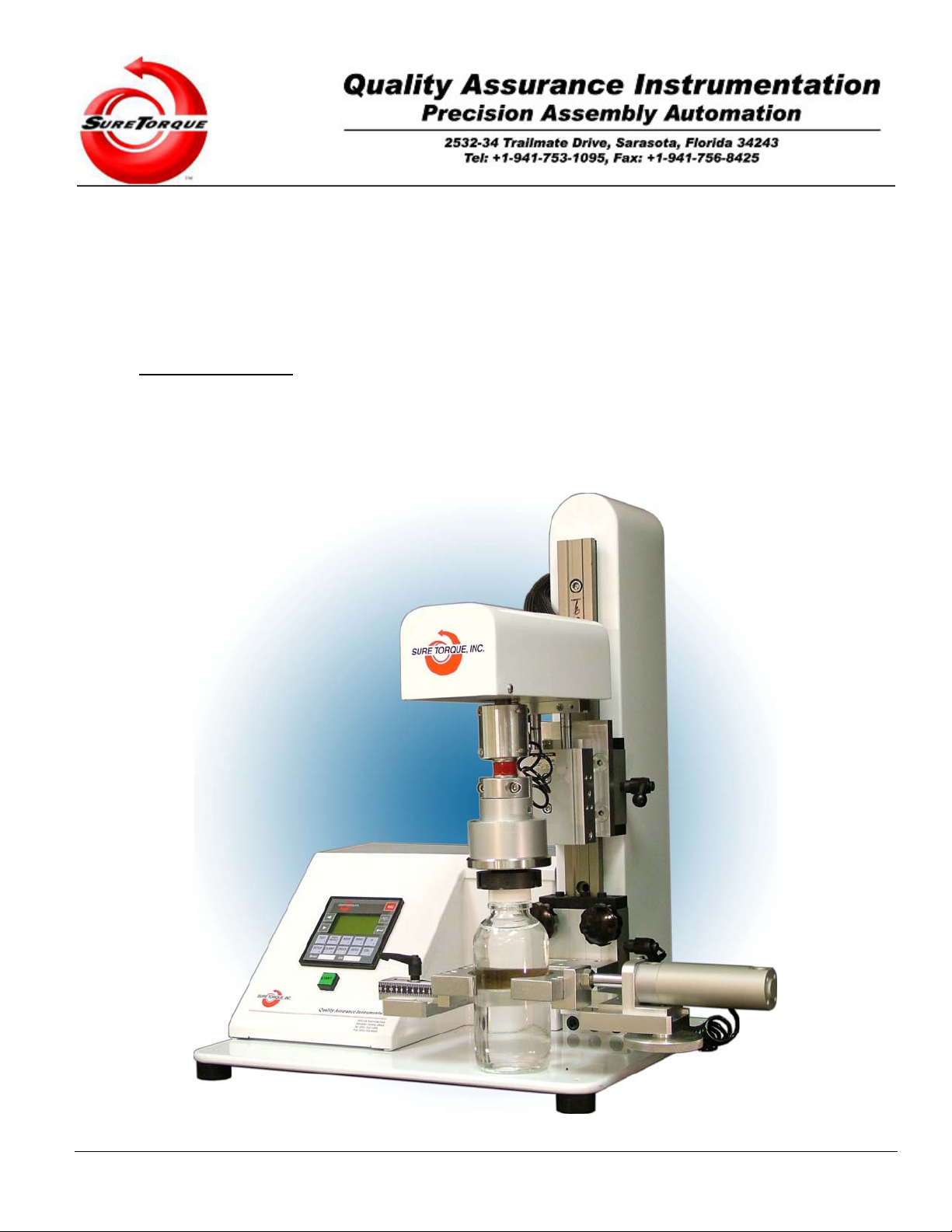
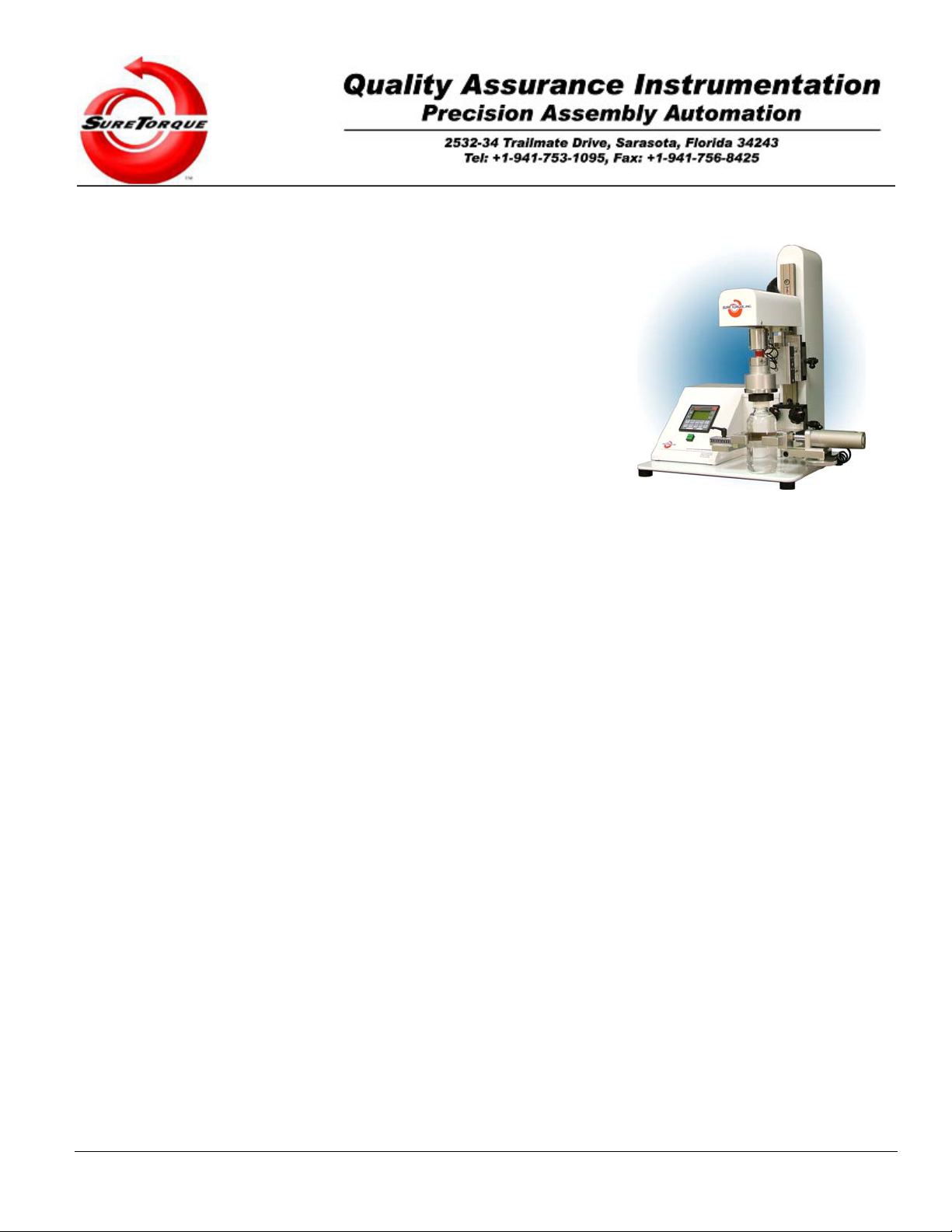
Major components and assemblies are called out on Figure 1-1, ST-LAB Torque Tester General Arrangement,
and referred to in this chapter, and throughout this manual as well. Any optional equipment included with your
machine is listed on the Owners Fact Sheet. Any Changeover specifications are listed on the Machine Tuning Sheet
for the particular closure and container being tested.
Your ST-LAB, “Sure Torque” Electronic Torque Tester, is a fully automated precision instrument designed for a
wide array of container closure test functions. The ST-LAB electronically measures the forces required to apply or
remove threaded screw caps from the containers. Your ST-LAB, with available options, will also apply downward
forces to a childproof closure for the required protocol tests under the Poison Prevention and Packaging Act. The ST-
LAB can also be used for any other test that requires the measurement of an increasing rotary, or linear force to a
peak point, closure container compatibility or failure analysis.
The Sure Torque’s modular design assures minimum maintenance, ease of operation in a minimum of space, and
wide-range of container acceptance capabilities.
ST offers an optional 360° degree test mechanism (refer to section 7.2.1 in this manual) for our ST-LAB unit. This
option measures the largest release torque sensed during a full 360° degree turn of a closure.
1.1. System Overview
The following paragraphs are intended to give an outline of the major components and operational sequences
required to perform the ST-LAB, Sure Torque functions. Major components and assemblies are called out on Figure
1-1, ST-LAB Torque Tester General Arrangement.
The basic ST-LAB Torque Tester System consists of:
1. Control Enclosure.
2. Sturdy mechanical assembly.
3. Integrated pneumatic systems.
4. Electronic components and assemblies required to perform various operational test functions.
The following four sections give a detailed description of each of these assemblies:
1.1.1. Control Interface
The operator’s interface with the Sure Torque unit is controlled through the PLC mounted in the head of the ST-
LAB that regulates the operational cycles, processes the input/output data, and acts as the overall communications
link with the line operator or test engineer. This PLC can easily interface with an on-line or remotely operated host
computer for data collection. Sure Torque will gladly integrate this host computer interface controller PC in your
system.
1.1.2. Mechanical Assembly
The Mechanical System consists of a Base, Chuck and Change Part Components. Please refer to Figure 1-2, ST-
LAB Torque Tester Mechanical Components (Chuck Assembly).

rev. 08.15.2006. 1-11
ST-LAB
MECHANICAL COMPONENTS
Figure 1-1, ST-LAB Torque Tester General Arrangement.
Figure 1-2, ST-LAB Torque Tester Mechanical Components (Chuck Assembly).

rev. 08.15.2006. 1-12
1.1.2.1. Stand Assembly
The Base is an aluminum fixture which supports the Container Platform, Clamp, Chuck, and ST-LAB Control
Head Assembly. The stand has a wide stable base to minimize motion during the test cycle, and a rugged main
support post on which the neck clamps and the chuck platform is attached. The neck clamps manually raised or
lowered to accommodate the different container / bottle heights and locked into position by a “quick-release” half-turn
locking handle.
On top of the stand’s Main Column (slide or support post) is the ST-LAB’s Main Head Assembly, which contains
all of the main pneumatic and force-sensing components required for the actual torque testing function operations.
The base of the control head assembly is a solid aluminum plate, which acts as a sturdy mounting surface for all
these components. The cover of the control head is removable for component cleaning, servicing and calibrating.
1.1.2.2. Chuck Assembly
The Chuck is the mechanical component, which holds the Collet that “grasps” the various closure devices, and
transmits the force to actually remove the closures. Both the “grasping” and the “turning” forces of the Chuck are
applied pneumatically, via electronic control. The Chuck rotates on a shaft, actuated by the pneumatic Test Cylinder
located in the Main Head Assembly. This Test Cylinder applies the required force to perform all torque-test functions.
1.1.2.3. Change-Parts
Each different container and closure “combination” requires a different set of change-parts, (please refer to the
Machine Tuning Sheet for the required change-parts for the particular container/closure combination being tested).
The change-parts, (or tooling package), for the basic ST-LAB consists of:
a. Container Base Clamp (when applicable) holds the container’s base.
b. Container Neck Clamps which hold the container’s neck as close to the closure as possible.
c. Closure Collet, which actually “grasps” the closure during the test cycle.
1.1.2.4. Pneumatic Assembly
Understanding the Pneumatic Assembly and its components is the key to understanding your ST-LAB Sure
Torque system and receiving optimum production and maintenance free operation from your unit. Please refer to
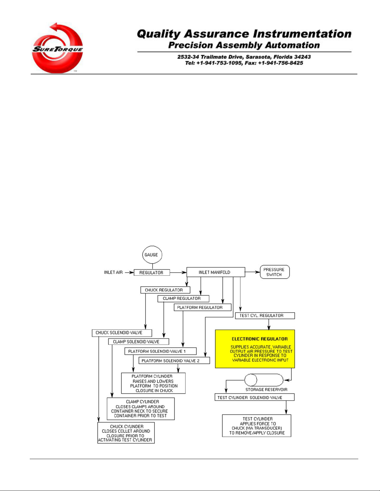
Figure 1-3, ST-LAB Pneumatic Diagram.
The pneumatic components control these 4 major Sure Torque functions:
1. Holding the container, (the Clamp function).
2. “Grasping” the closure, (the Chuck function).
3. Raising and lowering the Platform.
4. Activating the Test Cylinder to apply or remove the closure.
The Pneumatics Operational Philosophy is as follows:
Air pressure is applied to the ST-LAB through a panel-mounted regulator. ST offers an optional filter package for
those locations, which do not have a clean air supply.
The central air supply is then distributed via an inlet manifold to four regulators, which individually control the air
supply to the four main operation functions listed above. The manifold air supply is also monitored by a pressure
switch that will warn the Sure Torque operator if incoming air supply falls below a preset value. The air pressure is
sent directly to the Platform, Clamp, and Chuck air valves, which control the air cylinders that activate these
components.
The air pressure to the Test Cylinder, however, is first routed to a special electronic regulator, and a small
cylindrical storage reservoir. The electrical regulator is an electrically operated, pneumatic control device that utilizes
a variable electronic input signal to control a pneumatic output pressure. The input voltage to the electronic regulator
is steadily increased, producing an increase in the output pressure to the Test Cylinder, thus increasing the Chuck
torque for both the applying and releasing of closures. This output pressure is not affected by changes in input
pressures that may occur from normal plant air variations.
rev. 08.15.2006. 1-13
The small Air Storage Reservoir, located between the electronic regulator and the Test Cylinder, provides
smooth, pulse-free and constant pressure airflow to the Test Cylinder, smoothing out the rates of change in the
pressure being fed to the cylinder. This airflow of constantly increasing pressure produces a pulse-free and smoothly
increasing “force” that allows very accurate readings of peak torque values. Clean airflow to the Test Cylinder is
critical for proper operation of this component, and that of the overall machine as well.
Adjusting the “Release/Applied Impulse Time” in the set-up menu regulates the rate of increasing the air
pressure. This number is expressed as 00:00:00 (minutes:seconds:milliseconds) and usually it is in the milliseconds
range. Faster/less accurate or slower/more accurate torque application may be configured with this timer. It directly
controls the rate of the impulses on the PLC output, and this rate is proportional to the torque applied by the chuck.
The rate is programmable in 2 modes. In the first mode the rate is automatically adjusted by the PLC, and this
method is based on special considerations to low torque application (syringes) and high torque applications as well (1
gallon container for chemicals). This mode is optional and does not come with the default configuration. In the other
modes, the operator can change the rate to a static value. The faster the torque application rate is, the worse the
accuracy of the measurement and the shorter the cycle time. A slower rate minimizes the effects of acceleration on
the final torque reading.
It is important to understand that the decreasing this timer will make the torque application faster, while increasing
this timer will make the application slower, because the torque is proportional to the number of the control impulses,
and this timer changes the frequency of these control impulses.
The overall speed/accuracy performance is highly affected by the starting PWM rate as well. This number
controls the zero offset of the torque application. By default we configure the testers with 0 lbfin zero offset, but in
many cases it is adviseable to evaluate the best starting rate for the specific torque application.
Figure 1-3, Standard ST-LAB Torque Tester Pneumatic Diagram.

rev. 08.15.2006. 1-14
1.1.3. Electronic Assembly
A basic knowledge of the Electronic Assembly and related components will aid greatly in the understanding of the
function of your ST-LAB Torque Tester.
The main electronic components of the ST-LAB are as follows:
1. The Transducer and the signal conditioning/PLC interface circuit.
2. The PLC.
1.1.3.1. Transducer
The force applied to the Chuck by the Test Cylinder (the application or removal torque), is measured by an
electronic Strain Gauge Transducer. A strain gauge operates by measuring minute changes in a solid-state electrical
conductor as it is flexed or strained. The changes show up as measurable increases or decreases in electrical
resistance to a current flow through the conductor caused by the variation in the cross-section of the conductor.
The Transducer in the ST-LAB is designed to compensate for temperature, vibration and other possible causes of
resistance variation, and to convert the change in electrical resistance into a linear electrical signal, which is
proportional to the force applied to the closure device. In this way, the mechanical force (torque) applied to the
closure device is converted into an electrical signal. This signal is then sent to the PLC, which monitors the torque,
and controls the operating functions of the ST-LAB Sure Torque system.
1.1.3.2. Programmable Logic Controller
The PLC monitors the torque signal and records the peak signal as the actual application or removal torque. This
signal is displayed on the digital display on the screen of the PLC, and can also be output to a variety of data
collection/analization devices.
The PLC also controls the operating cycle of the Sure Torque system. Additionally, the PLC can display
diagnostic and error messages and allows the operator to program various parameters of the test cycle to achieve
optimum performance and accuracy.
1.2. Operational Sequence of the Test Cycle Functions
The basic operational sequence of your ST-LAB Sure Torque system is as follows:
1.2.1. Clamping Sequence
In the first step of the Sure Torque’s operational cycle, the Clamp air cylinder is activated and closes the Clamps
around the neck of the container being tested. Since each set of Clamps has been made to fit a particular container,
the container is firmly held in place, preventing it from bending, twisting or slightly rotating, thus affecting the closure
test results.
1.2.2. Head Lowering Sequence
The second step in the operational cycle is to pneumatically lower the head on which the chuck has been placed.
The head lowers to a height at which the container closure is securely inserted into the Chuck mechanism.
1.2.3. Chuck Actuation Sequence
In the third step in the operational cycle, the Collet closes around the closure being tested, and securely “grasps”
the closure prior to the Chuck rotating it either on, or off the container.
1.2.4. Torque-Test Sequence
In the fourth and final step of the operational cycle, The Test Cylinder is activated, and the torque applied to the
closure being tested is linearly/adaptively increased. The peak torque applied to the closure is measured by the
Transducer. The measurement is displayed on the digital display of the PLC and is available for other optional
functions, (eg: data collection and reporting, statistical analysis, graphic printout, automated capper torque control,
etc.).
The factory default operational test mode of the ST-LAB is the release mode, but it may be programmed to some
of the other available operational mode screens as well in the Miscellaneous Setup screen.

rev. 08.15.2006. 2-15
2. Installation Instructions
The following paragraphs explain the required information and procedures to properly install your ST-LAB Sure
Torque Electronic Torque Tester. CAUTION
Read this section completely before installing your new unit.
2.1. Receiving the Unit
Your ST-LAB Sure Torque System is shipped with the mechanical component already assembled. It has to be
hooked up with the electronic control unit, the air supply and the optional printer and/or computer.
2.1.1. Inspecting
Sure Torque urges you to give your machine a complete inspection as soon as it is received. Any machine
damage and/or missing parts should be reported to Sure Torque immediately.
CONTACT:
SURE TORQUE
2532-34 Trailmate Drive
Sarasota, Florida 34243
Phone: (941) 753-1095 Fax: (941) 756-8425
IMPORTANT
Please Follow These Simple Inspection Steps:
1. Check the packing list that accompanies the equipment to ensure that ALL loose parts have been included.
2. Check the unit completely for possible shipping damage.
3. Check the unit completely for any screws, bolts, belts, wheels, or other parts that may have loosened
during shipment. These parts should be tightened and/or properly adjusted before operating the equipment.
4. Assemble the unit according to the following Unpacking instructions.
2.1.2. Unpacking
Remove all packing, shipping wire, and/or other materials that might interfere with machine operation or safety
and proceed with the following unpacking and set-up procedures.
IMPORTANT
To unpack and set up your new Sure Torque
Electronic Torque Tester, follow the steps below:
NOTE:
Tools needed: Screwdriver, Allen wrench set.

rev. 08.15.2006. 2-16
1. Carefully remove the crating box cover to expose the machine, which is mounted on the crate’s base. Then
using a screwdriver, unscrew the screws.
2. Next, unscrew the screws holding the machine tight in the crating box then identify the other components
and assembly hardware.
3. Connect the main air supply to the rear of the machine (refer to section 2.5.1 in the manual for
specifications).
4. Attach the provided power supply to the rear of the unit.
5. Turn on the unit by pushing the switch on the rear of the machine.
6. Run unit in manual cycle first to check component operation and alignment before running automatic cycle.
IMPORTANT
See “Section 3, Operating Instructions” for complete instructions.
2.2. Positioning the Unit
Simply place the Sure Torque unit on a large table or flat platform allowing plenty of side room to perform
proper torque testing in an uncluttered area. Only qualified personnel should move or install this equipment. Failure
to comply may cause equipment damage and/or personal injury.
2.3. Pre-Run, Sure Torque Check-out
NOTE:
The following six operators functions Must be performed prior
to the running and/or operation of the ST-LAB Sure Torque System.
1. Be sure the power on switch is off. Check that all electrical connections are installed as per the wiring
diagram and that no loose or unfastened wires are evident.
2. Connect the Power Supply to the unit. (Input: AC 100-250V, 50-60Hz, 1.3A, Output: DC +24V, 2.0A)
3. Hook-up a clean, dry, filtered air supply of 80 psi at 4 cfm. Connect the air line to the 1/8” NPT fitting at rear
panel of the Test Head. (If optional filter is installed, connect the air line to the 1/8” NPT filter inlet.).
4. Check that all pneumatic connections are installed properly, and that no loose or unfastened hoses or
lines are evident. With air pressure on, listen for any air leaks throughout the system, and correct. Set the
Regulator at the Rear Panel to 80 psi on the Pressure Gage.
5. Visually inspect the entire unit for any loose brackets, bolts, etc. Check to see that there are no loose items
on or around any of the moving parts.
6. Check to see that the Tuning Sheet adjustments are appropriate for the container size to be run. (Please
refer to the Machine Tuning Sheet in Appendix-A).
+1. Optional: Connect the communication cable (RS-232/RJ11) to the PLC’s COM port 2 (the bottom one, on
the back plate of the unit).
2.4. Electrical Installation
CAUTION
Damage to electrical components can result if improper electrical connections
are made. Be sure to check all connections before applying power.

rev. 08.15.2006. 2-17
WARNING
1. Only qualified personnel should perform electrical installation of this equipment.
2. To avoid electrical shock, do not install this machine with any power active.
Failure to comply with these Warnings, may cause
extensive equipment damage and severe personal injury.
2.4.1. Precautions
The electrical supply requirements of your ST-LAB Sure Torque are designed to meet your individual
specifications. Therefore, the Owners Fact Sheet in this manual should be checked before any electrical connections
are installed, or power is put to the unit.
2.4.2. Connections
All electrical connections should be made by a qualified electrician and in accordance with the local electrical
codes.
2.5. Pneumatic Installation
Individual regulators have been provided by ST (refer to Figure 1-3, ST-LAB Torque Tester Pneumatic Diagram).
Filtering systems for air supplies are the machine owner’s responsibility. Contaminated air will cause excessive
wear, erratic operation, and eventual failure of pneumatic components.
2.5.1. Air Supply
A clean and moisture-free air supply of 80 psi should be available to mate with the existing air connection on your
machine. Sure Torque recommends the use of a 5µ filtration.
2.5.2. Plumbing
Customers piping for the air supply can run to the rear of the machine from any convenient point.
2.5.3. Air Pressure Settings
Normal pressure setting for operation is 80 PSI. The automatic pressure switch will shut down machine if inlet
pressure falls below 65 PSI.
2.6. Machine Tuning Sheet
(Refer to the Machine Tuning Sheet in the Appendix-A, accompanying this manual). The Machine Tuning Sheet
shows the recommended mechanical adjustments for the different change parts ordered with your machine. The
Tuning Sheet is a valuable tool for all those operating the ST-LAB Sure Torque Unit. It is recommended that this
tuning sheet be reviewed by All personnel involved in machine operation and change-over procedures, before
initiating machine start-up. Sure Torque should be contacted immediately if there are any questions or problems
pertaining to any specific Tuning Sheet data, its understanding, or application.
The final run and fine tune settings for your machine, may be slightly different from the ones on the Tuning
Sheet, thus, the customer’s set-up and change-over personnel should note these changes, for future
reference, on the Tuning Sheet.
SURE TORQUE Worldwide Torque Testing Equipment Specialists!
rev. 08.15.2006. 3-18
3. Operating Instructions
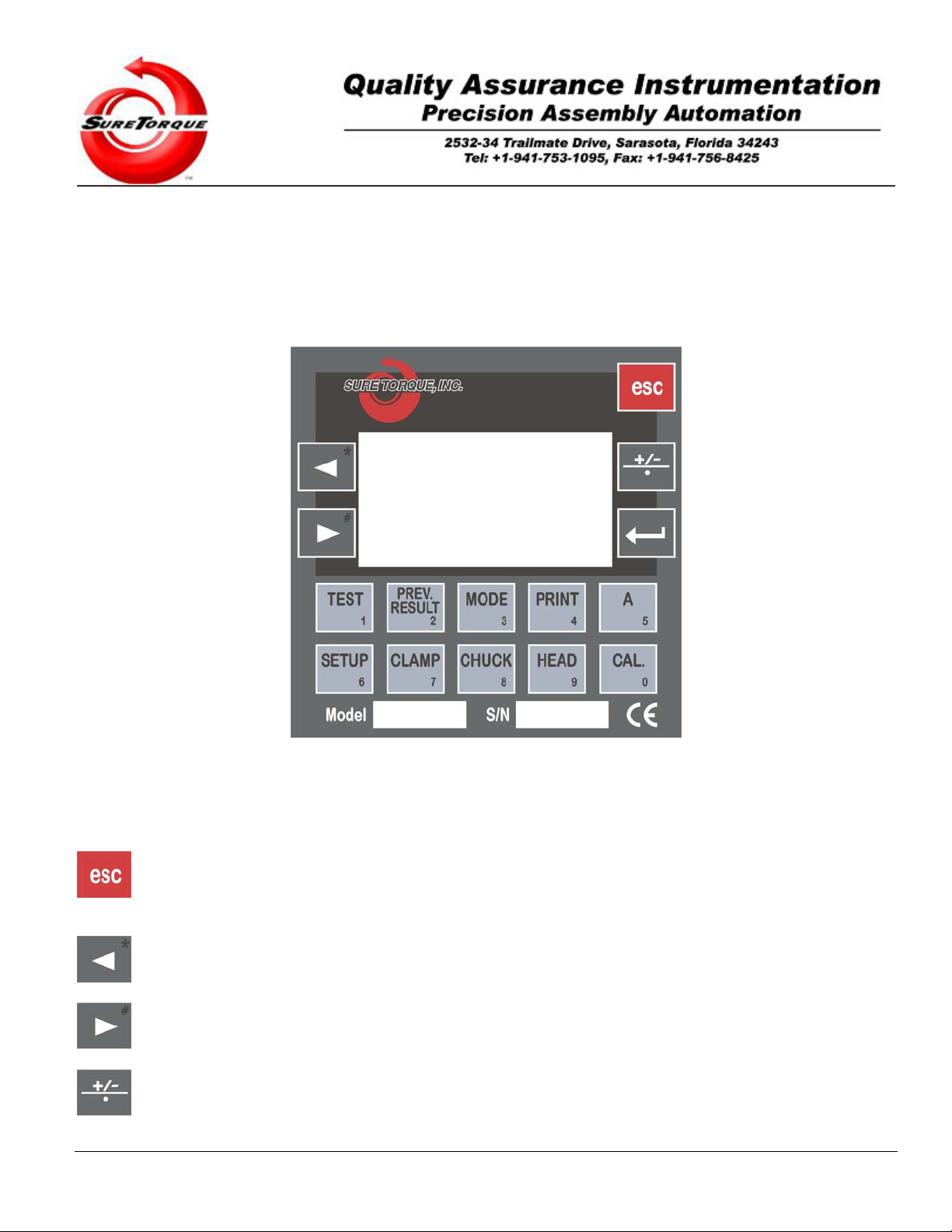
3.1. Controls and Indicators
The ST-LAB Torque Tester Control Unit has operator controls and indicators necessary for torque testing functions.
Refer to Figure 3-1, ST-LAB Controls and Indicators, for a drawing of all operator’s controls and indicators, listing their
types and functions.
Figure 3-1, ST-LAB Controls and Indicators.
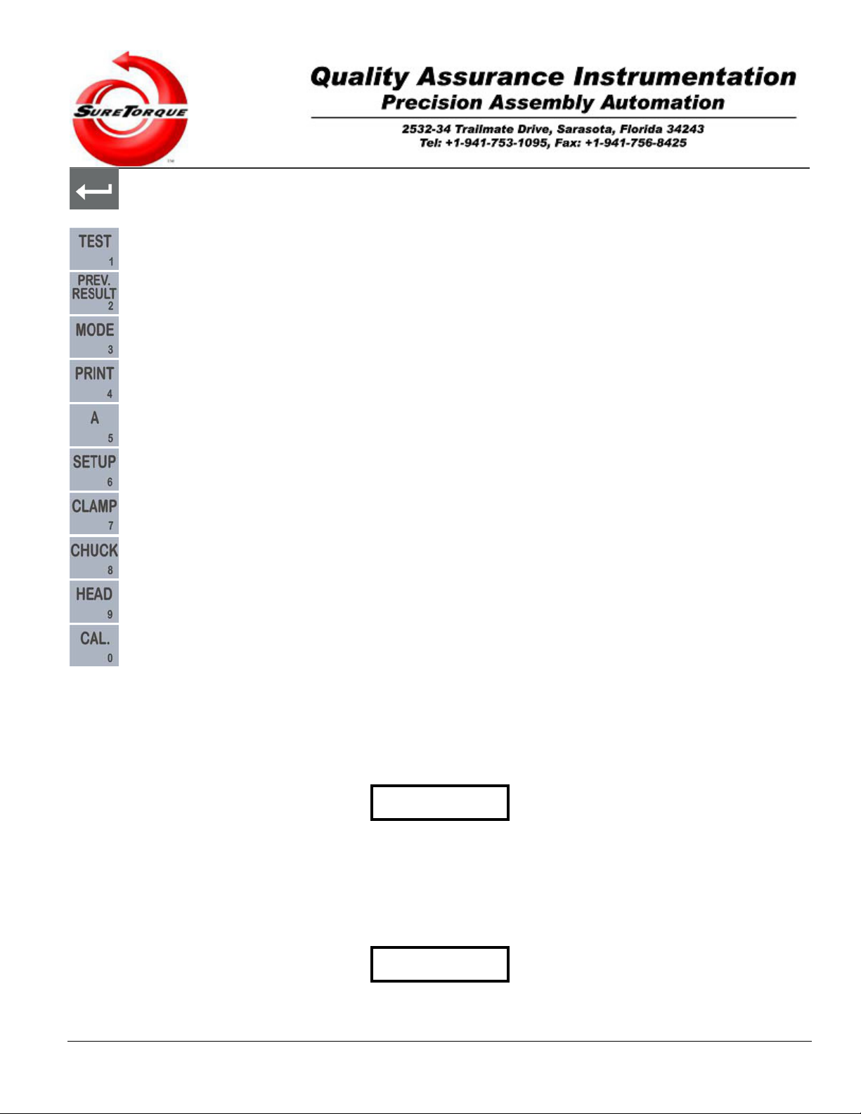
There are 15 push-button switches available to the user to operate the ST-LAB Sure Torque Control Unit. They are
used as “Soft Keys”; that is to say, their functions depend on the operational test mode in use.
- This button is used to go back to the previous screen (on screens without edit fields), go forward to the next
screen (on screens with edit fields), or stop the machine and go back to the mode screen in which the operator
actuated the last test (while measurement is in progress).
- This button is used to navigate within edit fields/menu points and mode screens. In Manual Mode it is used to
decrease the torque, and on the historical screens it may be used to navigate between the records.
- This button is used to navigate within edit fields/menu points and mode screens. In Manual Mode it is used to
increase the torque, and on the historical screens it may be used to navigate between the records.
- Toggles the topload application switch in Manual Mode, when the tester is equipped with the topload option.
rev. 08.15.2006. 3-19
- This button is called “ENTER” (based on PC terminology), and used to get in submenus. Toggles the torque
application switch in Manual Mode.
- This button is used in Manual mode, to toggle the test output.
- This button is used to get in the historical screen.
- This button is used to select the operation mode.
- This button is used to send out historical data on communication port #2, when purchased.
- This button is used in Manual mode.
- This button is used in Manual mode.
- This button is used to toggle the clamp in manual mode.
- This button is used to toggle the chuck in manual mode.
- This button is used to toggle the table in manual mode.
- This button is used to check the device calibration and to start the calibration process.
3.2. Machine Setup
Prior to initial and/or routine machine startup, it is essential to perform a detailed and accurate inspection to the
overall system. As well, a proper “Set-up” procedure is necessary to assure the accuracy, and optimum trouble-free
operation of your ST-LAB Torque Tester.
IMPORTANT
Refer to Section 2, Installation Instructions, Section 2.3, Pre-run, Sure Torque Check-out Before attempting to start or
operate your ST-LAB Sure Torque System.
3.2.1. Mechanical Setup
Follow these procedures to assure proper ST-LAB Sure Torque set-up, and operation.
IMPORTANT
These steps must be performed whenever the size of the
closure and/or container to be tested, is changed.

rev. 08.15.2006. 3-20
To set-up your Sure Torque Unit, proceed as follows:
1. Install the proper Collet for the “closure” being tested into the Chuck Housing utilizing the Lock Pin
(Press Lock Pin handle button during installation and removal).
2. Push the “POWER” button On (located on rear of the head).
3. Go to Manual Mode/Control
Container Platform Adjustment:
4. Obtain a container to be tested, with its closure on and insert it to the collet. If it is CR collet and it is a
Child-Resistant closure, then make sure that the plunger has a fair spring load on the cap. Activate the “Chuck”
by pushing the “CHUCK” button on the keypad.
5. Press the “HEAD” and then the “CAL” pushbuttons, energizing the vertical actuators to the measurement
position.
6. Set the height of the Head, and the Clamp block with the container/closure to be tested in the chuck.
Manually set the height of the head block so the container will stand firmly on the base and tighten the locking
handle. Adjust the height of the clamp block, so the clamps will have a strong grip on the container and lock
the clamp block securely.
Adjusting the table’s regulator valve - on the back panel - compensates for the additional vertical force created
by the closure’s thread travel and any unnecessary pressure is reduced accordingly. On the “CR” type closure,
while setting up to engage the closure’s ratchets prior to obtaining thread engagement, the proper head height
is first set (static) conforming to the parameters described in your Sure Torque ST-LAB tuning sheet. Next, feel
the upward travel allowed in release mode by pulling up the head when only the low pressure valve is active.
By adjusting the table’s regulator valve to obtain a constant vertical load on the component and closure, this
assures a dynamic engagement of the closure’s ratchet feature.
Clamp Adjustment:
7. Set the Left Hand, Stationary Clamp in a position that will ensure a centralized position of the container on
the Platform.
8. Press the “CLAMP” pushbutton, energizing the Air Clamp.
9. Adjust the Air Clamp in or out until both stationary and moveable Clamp sections perfectly align the
container (and closure) in the Collet.
10. Press the “CLAMP” pushbutton, opening the Clamp.
11. Press “ESC” pushbutton to return to main menu, the tester is setup for your container.
Confirm your settings by running an automatic cycle:
13. Press “ENTER” on any mode screen to configure the desired torque and cycle settings (Password may be
required) then hit “ESC” to go back to the mode screen. Push the “MODE/Navigation Arrows” button(s) until
you reach the desired one, and hit the Start button to start the test.
14. Place the container/closure to be tested, onto the Container Platform snugly against the Stationary Clamp.
15. Press the Start buttons on the two sides of the head.
16. Read the “Applied”, or “Release” Torque finding for this particular test on the PLC screen at the end of the
test cycle.
3.2.2. Electronic Setup
The ST-LAB Setup Mode provides several options to set-up and alter electronic or pre-programmed software
settings. Select the Setup Mode using the arrow buttons on the main navigation screen, then hit ENTER. Depending
on the purchased configuration, the PLC will inquire you for your password on the next screen (the default password
to get in the setup is 1111). After entering the last digit of the password the “Password accepted” screen appears. If
the password is not accepted then the user may reenter the correct password or hit the ESC to cancel the password
Table of contents
Other Sure Torque Test Equipment manuals


