Sureguard Wireless Dog e-Fence User manual


2

3
Dog Fencing Re-envisioned
Sureguard's Latest Wireless Dog Fence.
Combines recent innovations in solar panel and battery technologies.
Prevent Your Dogs
•Jumping, Climbing & Digging at fences.
•Digging up your garden.
•Escaping through an open driveway.
•Running at speed to escape or chase other animals.
How does the Wireless Dog Fence Work?
Install the Boundary Wire to create the no-go area. At a pre-set distance the Radio Collar
warns your dog to stop. If your dog ignores this opportunity to back away, then the collar
emits a static correction. It is safe and humane because your dog is in control of the
situation. Some initial training teaches your dog.
Is this like an electric fence? No, there is no electrified wire to touch.
What’s in the Box?

4
Specification
Energiser
•Maximum Boundary Length: 1600m
•Minimum Containment Area Width or Length: 10m
Radio Collar
•Wearing Duration: Maximum 12 hours in any 24-hour period.
•Dimensions: 55.7mm x 41.6mm x 30.0mm
•Weight: 53g
•Ingress Protection Rating: IP57 (30 minutes water immersion at 1m)
•Activation Distance: Each collar individually adjustable approximately 1m to 4m
•Correction Levels: 10
•Correction Output Min: 31mA peak, 2.3mA RMS, 0.4mJ/S
•Correction Output Max: 77mA peak, 34mA RMS, 12mJ/S
•Battery Running Time: 1 to 6 Months (depends on amount of correction)
•Battery Charge Time: 3 hours
Collar Fabric
•Dimensions: 19mm wide, 1.8mm thick.
•Sizes:
oSmall-Medium 20cm to 40cm
oMedium-Large 30cm to 62cm
•Material: High grade TPU with encapsulated nylon webbing.

5
Boundary Design
To create your no-go area, place the
Boundary Wire along fences, around
garden beds, across lawn areas, across
open driveways and gates, etc.
The Boundary Wire may be pegged to the
ground, covered, buried or attached low
down on a fence.
Example 1: Simple single wire installation
around the whole property. The Activation
Distance is selected on the collar.
Example 2: Doubled Wire installation for
customised shapes. The Doubled Wire
technique loops back on itself with a wire
separation of between 30cm and 2m.
Activation Distance on the collar is set to
maximum. The wire separation governs
the Activation Distance (small separation for shorter distances).
See the next two pages, examples 3,4,5,7,8 & 9.
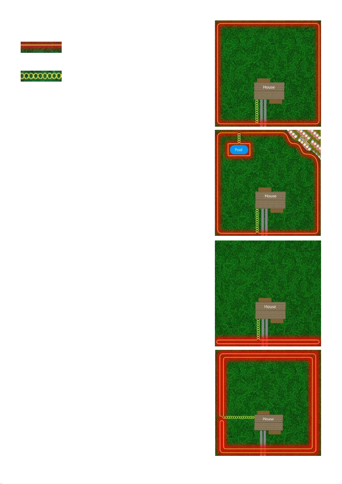
Boundary Wire Examples
Your Wireless Dog Fence boundary can be as simple or intricate as you need. The following
examples illustrate various wire installations to achieve different effects.
NOTE:
1/ In the following examples we've located the Boundary Wire Energiser at the house, but it
can generally be installed anywhere in sunlight.
2/ “Activation Distance” is defined as the distance between the Boundary Wire and when
the Collar begins to detect signal (see page 16).
3/ No matter what design you employ, the boundary is formed by only ONE piece of wire
and each end of this is connected to the Boundary Wire Energiser.
Tip: Do you have areas where you don't want the Boundary Wire to activate your dogs’
collars? Sureguard makes a Dual-Wire that creates a cancellation of the signal while still
allowing the main signal to pass to other areas of your boundary. By deleting the signal,
your dog's collar won't activate next to this Dual-Wire.
6
KEY Features:
Yellow represents the Boundary Wire and
Red the radio signal.
This double Yellow represents the Dual-
Wire with signal deleted.
(1) Simple Boundary
The most common installation is this simple boundary
design consists of a single wire running around the whole
property. The Collar’s Activation Distance is constant
around the boundary. Notice no signal is emitted from
the Dual-Wire running back to the house.
(2) Inner Boundary
It is possible to create a no-go area inside the main
boundary. Notice the Dual-Wire used to divert signal
from the main boundary to the wire around a pool area.
Your dog's Radio Collar will activate around the pool and
main boundary. However, around the pool it will be a
shorter Activation Distance. See (9) on page 7.
(3) Frontage Only
To protect a full single boundary, install a long thin
rectangle as illustrated. This is called a Doubled Wire
installation. The width of the rectangle is a minimum
30cm but can be up to 2m for greater Activation
Distance. (Adjust as required). This design may also be
used to protect small areas, for example, around an open
driveway. Install the rectangle at least 2m beyond the
opening, and at least 1m apart. So, for a typical 4m wide
driveway, the rectangle is at least 8m by 1m. For more
details, refer to illustration (9) on page 7.
(4) Small Properties
When the minimum dimension (width or depth) of your
containment area is around 10-20m, you MUST install a
Doubled Wire as illustrated. It is a technical requirement
of radio collar systems. This design makes the radio signal
diminish rapidly with distance thereby reducing false
triggering of correction inside the containment area.

7
(5) Cancel Boundary
Use the Dual-Wire as illustrated to cancel the signal on a
small section of the boundary. Your dog will have access
to this area.
(6) Incorrect Usage
This example shows a common mistake when using Dual-
Wire to cancel the signal. When the signal travels through
each of the dual wires in the same direction, the signal
does not cancel.
(7) Backyard Only
This doubled wire configuration confines your dogs to the
backyard while still allowing them access to the back
door.
(8) Vary Frontage Activation Distance
For more effective containment on the frontage, increase
the wire separation for a greater Activation Distance.
(9) Doubled Wire –Increasing Activation Distance
You can increase the Activation Distance of Doubled Wire
installations in two ways.
1/ Increasing the separation of the wires up to 2m apart.
2/ Encircling the boundary 2, 3 or 4 times. More turns
give greater distance. Refer to illustration (9).
NOTE: This is a single continuous piece of boundary wire
Use this technique on open gateways and driveways, and
on inner boundaries like example 2.

8
Wiring Techniques
•Try to keep the wire at about the same height above or below ground otherwise the
Activation Distance will vary around the boundary.
•The Activation Distance at corners can be greater than straight sections because the
signal is detected from two directions at once and added together. If the
containment area is small, you may want to reduce this effect by:
Simple Boundary –Starting 2m to 4m from each corner, gradually raise the wire to
the top of the corner. Ramp back down over the same distance after the corner.
Adjust wire corner height to adjust the Activation Distance at the corner.
Doubled Boundary –Starting 2m to 4m from each corner, reduce the separation
between the doubled wires. Smaller separation reduces the Activation Distance.
Testing Distance - Set the collar to Training Mode and check the Activation Distance.
•Burying the Boundary Wire is optional. Depth between 5cm and 20cm. DO NOT bury
damaged, repaired or joined sections of wire.
•Wire Tie-Down Pegs (see Starter Kit) are a convenient alternative to burying.
•Do not create a trip hazard with the wire!
•Protect the wire when crossing a driveway. On concrete you might push the wire into
the expansion joint. With gravel you MUST protect the buried wire inside hard PVC
conduit. Over bitumen, use soft black polythene irrigation pipe which can be driven
over. On pavers you can often lift them and place the wire directly underneath.
•Signal anomalies: Keep the boundary wire at least 30cm from large steel objects
because the radio signal can distort into and around them. This may cause the collar
to activate where you do not want. Steel may also reduce the Activation Distance.
Check your Activation Distance around the full perimeter before your bury wire!
Steel Object
Problem
Solution
Steel framed house or
staircase.
False activation near
metal frame.
Install like #4, #5, #7 or #8.
Shed/Car/Trampoline/etc.
next to Boundary Wire.
Collar may activate
around the object
Increase distance between wire to object or
install like #4, #5, #7 or #8
Steel Fence.
Activation distance may
be shorter than non-
metal fenced areas.
Difference may be acceptable. If not, move wire
at least 20cm away from the metal fence.
Cattle Grid
Activation Distance may
be reduced significantly.
For single or doubled wire installation, keep the
boundary wire at least 30cm from the cattle grid.
For doubled wire installation, increase the
minimum rectangle from 1mx8m to 8mx8m.
Concrete Driveway
Activation Distance is
shorter in this area.
Increase Activation Distance on the collar. Check
if this is acceptable for other areas. Or, consider
wiring like example #8.

9
Joining & Repairing Boundary Wire
Wherever the Boundary Wires are joining, always use Sureguard heat shrink caps. Some are
included in your kit and more can be ordered separately. DO NOT substitute: electrical
tape, wire nuts, automotive connectors, solder splices or ordinary heat shrink.
Boundary Wire Energiser - Features

10
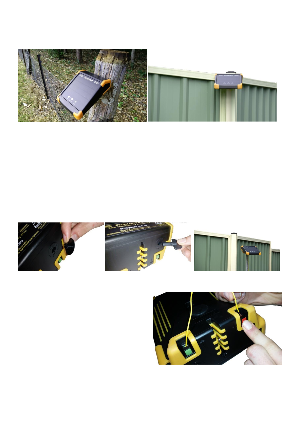
Mounting Location
The Energiser is solar powered so must have an uninterrupted view of the sky from east to
west. The Energiser should face towards the equator; in Australia that means northward. In
the northern hemisphere the equator is southward. The solar panel will charge quickly in
full sunlight. In cloudy conditions the solar panel collects power from the full view of the
cloudy sky. The intensity is lower, and the charge time is longer. If the battery power
indicates low, you should check to validate your solar setup. Low battery is not typical.
NOTE: The Solar Panel only charges while the Energiser is switched ON
and connected to the boundary.
Mounting Options
The Energiser has several mounting options –see points #3, #4 & #6 illustrated on page 9.
Plastic Mounting Post
To use the plastic Mounting Post, assemble its three parts. Remove the protective rubber
bung (see point #6) and push the post firmly into the base of the Energiser. Push the
pointed end of the post into soil or screw it to an existing fence using two 25mm Saddle
Clamp (clamps not included).
11
Screw Mounting
Insert a single M4 screw (4mm with head no more than 9mm) into timber, steel or plastic
fencing or posts to hang the Energiser using the screw mounting option (see Point #3).
Steel Post Anti-Theft Mounting
You can mount the Energiser on top of most sizes of steel posts or “star pickets” (see Point
#4 & #2). Check your local hardware store for sizes. The Energiser locks to the post using
the supplied key to open the mounting bolt. Locking Procedure: 1/ Remove the rubber
sealing plug off the key hole and insert the supplied key (see Point #2). 2/ Align the
mounting bolt (see Point #4) with the top hole in the post. 3/ Rotate the key anticlockwise
to retract the mounting bolt. 4/ Push the Energiser onto the post. 5/ Rotate the key
clockwise to lock. 6/ Make sure the mounting bolt is passing through the hole in the steel
post. The Energiser should not pull off. 7/ Remove the key. 8/ Reinsert the rubber seal.
Connecting to Boundary Wire
Prepare both ends of the Boundary Wire:
1/ Remove 12mm of the yellow insulation.
2/ twist the exposed copper wires together.
3/ Fold the twisted copper wires back over
themselves 5mm to double the thickness.
Then push the Green Terminal button to
open the metal jaw, insert the copper wire
then release the button to hold the wire.
Repeat for the Red Terminal. It doesn’t usually matter which wire end goes to which
terminal, however, the Activation Distance can vary up to 30% by reversing the polarity.
This can be useful to fine-tune the system to get more distance or less distance.

12
Switch Energiser ON
Using the Energiser is as simple as pressing the ON/OFF
button on the underside of the case (see Point #7).
When the Energiser is switched ON you will see two LED
lights (POWER and FENCE) glow continuously Green. GREEN
means you are good to go! The lights may also glow RED or BLUE depending on your fence
or device Status. Refer to the Table below for details.
NOTE: Critical issues will cause the LED to flash RED & alarm buzzer (if active) to sound.
What the LED Colours Mean:
NOTE: For troubleshooting procedures, please refer to Rectifying Power Faults and
Rectifying Fence Faults later in this manual.
POWER
LED
GREEN
Normal operation. The internal battery has plenty of power.
RED
The internal battery is low. Check solar panel is clean and setup correctly.
RED
FLASHING
Critically low battery. Rectify immediately!
BLUE
Displayed while using the advanced option setting switch.
NO LIGHT
Standby Mode because the battery is very low. Leave the device switched
ON in full sun and wait for it to charge.
FENCE
LED
GREEN
Normal operation. The Boundary Wire is active.
RED
Transmission fault occurred during the last 24 hours but is currently okay.
This may indicate an intermittent fault or that you disconnected the wire.
RED
FLASHING
Transmission fault: Check for Boundary Wire breakage. Rectify
immediately! Your dog’s collar will not operate in this state.
BLUE
You have selected the ON/OFF Timer. The transmission is currently inactive.
NO LIGHT
Standby Mode because the battery is very low. Leave the device switched
ON in full sun and wait for it to charge.
Advanced User Features
The cog icon on the solar panel is a
touch switch. The touch switch is
activated for up to 60 seconds whenever
the Energiser is switched ON. During this
time, you can customise the operation of
the Energiser.

13
How to Use the Touch Switch
1. Touch the cog icon for about 1 second until you see both LED lights glow BLUE.
TIPS: Touch lightly, don’t press hard. If your finger is small, use your thumb.
2. As soon as you see both LEDs glow BLUE, remove your finger off the cog.
3. Wait briefly until the BLUE LEDs switch off.
4. Momentarily touch & release the cog icon. The number of times you touch and
release the cog determines the function you select, as per the meaning below.
TIP: You’ll find the switch responds best when you move your finger at least 2cm
away from the cog each time you touch.
❖Touch once: (Function #1)
Reset all options to factory default, then the device tests the hardware as follows:
1/ LEDs. 2/ Alarm Buzzer. 3/ Solar charger. 4/ Reboot automatically after 20 seconds.
❖Touch twice (Function #2):
Timer is switched OFF. Energiser will operate 24 hours a day. (Factory default).
❖Touch 3 times (Function #3):
Timer is switched onto Night Mode & will only operate at night (from 30 minutes
after sunset). During the day the Energiser is OFF and the FENCE LED glows BLUE. The
buzzer is set to 24-hour mode but can be customised with Functions #5, #6 or #7.
❖Touch 4 times (Function #4):
Timer is switched onto Day Mode & will only operate during the day (from 30
minutes after sunrise). At night the Energiser is OFF and the FENCE LED glows BLUE.
❖Touch 5 times (Function #5):
Internal alarm buzzer is switched OFF. It will not sound if a status error occurs.
❖Touch 6 times (Function #6):
Internal alarm buzzer will only sound during daylight hours. (Factory default setting.)
❖Touch 7 times (Function #7):
Internal alarm buzzer is switched ON and can sound at any time of day or night.
❖More than 7:
Does nothing. Beeps an error.
Rectifying Power Faults
POWER LED Flashing RED:
1/ Check the solar setup. The panel must be clean, facing toward the equator (not east or
west), not covered or experiencing shadowing and should see as much of the sky in all
directions as is possible (avoid trees and buildings).
2/ Do a solar panel self-test. This test is best performed first thing in the morning* before
solar charging starts. Select Function #1. At the end of the test cycle notice whether the
POWER LED flickers BLUE. If it does, this confirms the panel is working. After 20 seconds the
device will reboot. *NOTE: If the battery is already fully charged this test method is not
valid.

14
POWER LED Continuously RED:
This may happen during dark cloudy conditions. The Energiser will automatically lower its
power consumption to continue operation. We also recommend you check your solar
setup. The panel must be clean, facing toward the equator (not east or west), not covered
or experiencing shadowing and should see as much of the sky in all directions as is possible.
POWER LED is OFF:
The Energiser has entered a low power stand-by mode to avoid the battery becoming fully
depleted. This condition might happen if you forgot to switch the Energiser OFF when
putting it into storage. To rectify this, switch the Energise OFF for at least 24 hours. Then, at
the start of a sunny day, place the Energiser in FULL sun and switch ON. As it commences
charging, the Blue LED should flash briefly once per second. If it doesn’t, switch OFF for
another 24 hours then try charging again. If the battery still does not come good, contact
Sureguard for advice. After several hours, the Power LED will go GREEN and the fence
commence working.
Rectifying Fence Faults
FENCE LED Flashing RED:
Perform the following self-test of the Energiser:
1. Switch OFF the Energiser.
2. Disconnect the Boundary Wire from the Red and Green Terminals.
3. Attach a short piece of wire to connect the Red and Green Terminals together.
4. Switch ON the Energiser. If the Energiser works properly, this test indicates you have
a breakage somewhere on your Boundary Wire. If the Energiser does not pass this
test, then call Sureguard for advice.
FENCE LED Continuously RED:
This indication happens whenever the transmission experiences a fault but then restarts.
The LED Status will reset at midnight or when you switch the Energiser OFF then ON. This
fault could happen during setup if you broke the Boundary Wire. It can also indicate an
intermittent break in the Boundary Wire. You can reset this at any time by switching the
power OFF, waiting 10 seconds, then switching back ON.
NOTE: The battery only charges while
the Energiser is switched ON.

15
Radio Collar Receiver
Illustrated Features
Collar Fabric
Collar Receiver
Correction Probes
Charging Port
Correction Control
Status Light
Distance Control
Correction Control
OFF is the position you should select when the
collar is not in use. Rotate the Correction Control
knob slightly clockwise to switch the collar ON.
AUTO position will automatically increase the
correction based on your dog’s recent history of
attempted escapes. This takes the guess work out
of selecting a manual correction setting. After you switch the device ON, AUTO starts at the
lowest correction level #1. The level increases after each attempted escape. Once your dog
stops trying to escape, the correction level will automatically reduce over a few weeks. To
select a manual correction level, continue to rotate clockwise. MAX is the maximum
correction level. There are 10 levels of correction, but the intensity of MAX is about 30
times that of level 1. Level 1 is low and designed for sensitive dogs. MAX is high and
designed for stubborn dogs.
In TRAIN position the correction is switched off. Use this for: 1/ Initial training (described
later). 2/ Whenever you adjust or test the Activation Distance.
Distance Control
The Activation Distance is the distance between the Boundary Wire and the maximum
distance at which the collar starts to sound its warning. MIN is less than 1m. MAX can be
4m or more. Each collar may be set to its own distance according to your dog’s behaviour
or the type of boundary you have. (See Guidelines below). For best results we recommend
a greater distance during the first week or so which can be reduced once reliable
containment is achieved.
16
How to Set the Activation Distance:
The radio antenna inside the collar “looks” for the radio signal through the front of the
case, basically in the same direction your dog looks. To set the Activation Distance:
•Rotate the Correction Control knob to position TRAIN.
•Rotate the Distance Control knob to MIN.
•Hold the collar as follows:
oAt the desired Activation Distance.
oAt the same height as your dog’s neck.
oWith the front of the collar facing the
boundary wire.
oWith the collar controls uppermost.
oWith the collar tilted slightly forward like your dog’s neck angle.
•Starting from distance-MIN, slowly rotate the Distance Control knob clockwise until
the warning sound starts. (NOTE: The control dial offers more precision for shorter
distances. Near the MAX setting the incremental change of distance is much more.)
•To check this setting:
oMove the collar away from the Boundary Wire until the sound stops.
oHolding the collar as before, move slowly toward the boundary.
oWhen the warning sound starts, this is the Activation Distance.
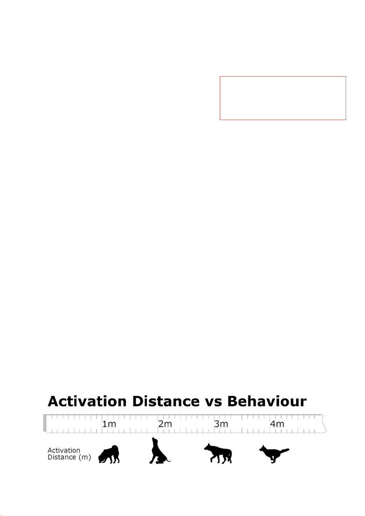
Activation Distance - Selection Guidelines:
Use the following as a guide. Keep the Activation Distance to less than 15% of your
minimum boundary dimension. For example, if your boundary is 20m by 100m then the
Activation Distance is best no more than 3m (15% of 20m).
•Dog digging under a fence: 1m or less.
•Dog walking into garden beds: 1-1.5m (depending on size of dog).
•Dog jumping a fence from stationary: 1.5-2m (depending on size of dog).
•Dog jumping a fence while running: 2-4m (depending on size & speed of dog).
•No fence and dog runs: Set to MAX (about 4m).
•No fence but dog doesn’t run: Set to MAX or 1/8th turn back from MAX
To set or measure the Activation
Distance you MUST use the
TRAIN position (page 15).
17
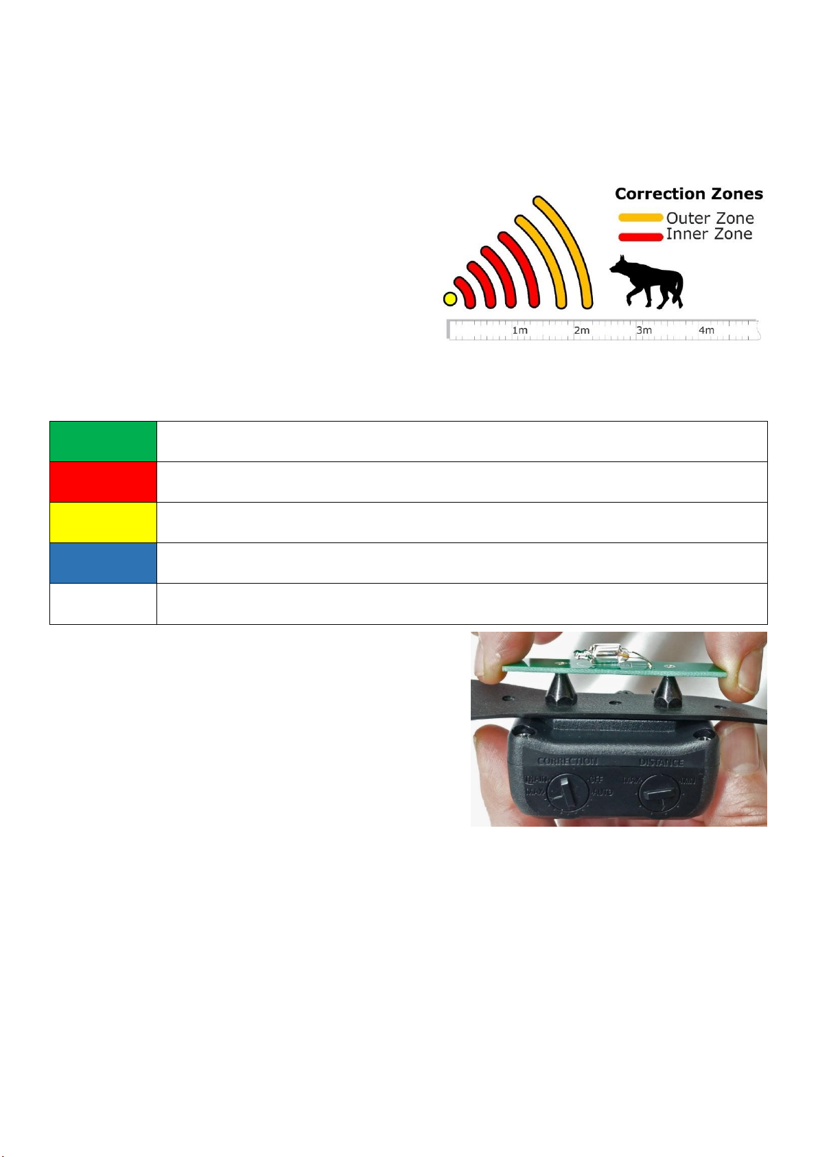
Activation Distance “Zones”
Around the Boundary Wire are two signal zones, as illustrated below. The Activation
Distance is the start of the Outer Zone. In the Outer Zone, the Radio Collar emits a warning
sound for 3 seconds before giving a correction, so your dog has time to back away. If your
dog enters the Inner Zone, the correction starts immediately. After 7 seconds of correction,
a cut-out will stop further correction, but the
warning sound will continue. When your dog
moves away from the zones the warning and
correction ceases. After a further 5 seconds
the collar will once again be ready to activate.
Status Light
The Status Light is a multi-colour light that tells you information about the collar’s operating
state. It flashes with a colour every 2 seconds (no sound) with meanings as follows:
GREEN
Normal operation. No issues.
RED
Battery is low. Time to recharge.
YELLOW
Collar is in Training Mode. Will not generate Correction.
BLUE
Your dog felt nothing during the last correction. Check fit & trim fur.
WHITE
The Recharge Adapter is connected and charging the battery.
BLUE Status
Your dog was corrected but nothing past through
your dog’s skin. Your dog felt nothing.
This is a serious problem. Rectify Immediately!
Perform all the following checks:
1. Trim the fur behind the Radio Collar so the
Correction Probes make good physical
contact with your dog’s neck skin. Do this even if you think your dog has short fur!
2. Ensure the collar is not loose. Adjust to a comfort fit. You should be able to insert two
fingers under the collar without it feeling too loose or too tight.
3. Test the collar voltage emitted from the Correction Probes:
a. Set Correction to MAX.
b. Firmly hold the Collar Tester against the two Correction Probes (see above).
c. Take the Radio Collar within 30cm of the Boundary Wire.
d. The tester should flash for about 5 seconds. If it doesn’t, contact Sureguard.

18
Escape Indicator
The Status Light normally flashes ONCE every 2 seconds. If your dog tried to escape during
the last 10-hours, the Status Light will flash TWICE every 2 seconds. If your dog tests the
boundary regularly, you should investigate your dog’s behaviour.
Battery Charger
The battery inside the collar will need
charging about every 1 to 6 months.
Battery life depends on the correction
strength and how often your dog visits
the boundary. Wait for the Status Light
to flash RED before charging. Then
recharge immediately. IMPORTANT:
Leave the collar switched ON because it
will not charge if you switch it OFF. Plug
the Power Charger into a wall socket.
Carefully lift the rubber bung from the
charging port on the rear of the collar.
Plug the charging cable into the
charging port. The Status Light should
glow white while charging is working.
When charging is complete the collar
will sound a momentary chime, then the Status Light will flash GREEN. Charging time is
about 3 hours. When the charger is finished, insert the rubber bung back into the charge
port so it protects the contacts. NOTE: If the Status Light is GREEN (meaning battery okay),
the charger won’t start. This is normal.
Correction Probes
For your dog’s comfort, Sureguard Correction Probes come in three lengths and are made
from low allergenic stainless steel. The probes sit next to your dog’s neck skin so it’s
important to choose the right length according to the thickness of fur. Most dogs will use
the short 10mm probes. If your dog has thick fur, then use the 15mm probes. The 10mm
and 15mm probes come standard in the Starter Kit. An optional 19mm version is available
for very thick fur.

19
Collar Assembly
Always use the collar fabric supplied. Other materials can
cause damage or interfere with the correction.
Adjust the collar size to fit your dog. You should be able to
comfortably insert two fingers under the collar without it
feeling loose. Mark the position of the buckle and remove
collar off your dog. Fasten the buckle again according to
your mark, then position the collar receiver diagonally
opposite as illustrated. Screw on the probes finger-tight.
After a few days on your dog, check to ensure the fit and
probe-length are comfortable.
When you have the right collar position, we recommend you apply Sureguard Threadlocker
to reduce the likelihood of the probes working loose. This is included in your Starter Kit.
Before commencing, read the full instructions on the bottle of Threadlocker Fluid. If you
have a puppy, you may want to delay this step while your puppy is still growing.
Follow these instructions (as illustrated):
1/ Place a 1mm to 2mm drop of Threadlocker onto just the END of one screw. It’s
important to avoid excess liquid running down the thread.
2/ Attach the probe just finger tight.
3/ Repeat step 1 & 2 for the second probe.
NOTE: When disassembling, a little resistance is normal but if the probes are locked, do not
force off with a tool - call Sureguard for advice.

20
Collar Maintenance
•The collar fabric is durable but eventually will need replacing. Use only Sureguard
approved collar fabric.
•If required, the collar may be cleaned. Only use mild soapy water. Never use cleaning
solvents or chemicals.
•The collar receiver is sealed for water tightness. DO NOT open it. Damage to the
water seal may void your warranty. No internal maintenance is necessary.
•Recharge the collar battery as indicated by a RED Status Light.
Problem Solving Collar Faults
*The Radio Collar activates everywhere inside the boundary.
The Activation Distance is too great and must be reduced. Adjust the distance control knob.
Alternatively, if your boundary width is less than 20m you should re-wire the boundary
using the Doubled Wire technique discussed on pages 6 & 7.
*The Radio Collar sometimes activates when well away from the Boundary Wire.
The collar may be sensing a signal at that location due to signal anomalies. To diagnose:
1/ Re-read the section “Wiring Techniques – signal anomalies”on page 8.
2/ The transmission signal radiates around the case of the Boundary Wire Energiser. If this
is causing false activation, then move the Energiser to a more appropriate location.
3/ The Activation Distance can be affected by ferrous metal objects worn near the Collar
Receiver. These can unpredictably make the receiving antenna inside the collar more
sensitive, which in turn might cause signal to be detected at a greater distance than you
originally set. If your dog is wearing a second collar, do not allow metal tags to dangle near
the collar and do not use metal chain collars.
*The dog’s neck is irritated by the collar.
This may be a pressure sore (pressure necrosis) or a shaving rash. Remove the collar and
wait for the skin to heal before using the collar again. If skin is broken, regularly apply an
antiseptic medication until healed. To rectify this issue, try:
1/ The collar is not intended to be worn continuously. Maximum wear time is 12-hours per
day. Try reducing the maximum wear time to 8 hours.
2/ Readjust the collar fit because it may be too tight. This will reduce pressure on the skin.
3/ When you cut the fur behind the collar box, never shave smooth to the skin but leave a
little fur to protect against rubbing the skin.
* Can I reduce the Radio Collar’s MIN distance or increase the MAX distance?
Try reversing the polarity of the signal by swapping the boundary wires between the red
and green output terminals. Take the boundary wire from the red output terminal and put
it into the green terminal and take the boundary wire in the green terminal and put it into
the red terminal.
Table of contents
Other Sureguard Pet Care Product manuals


