Surtek TRHB15 User manual

ATENCIÓN: lea, entienda y siga las instrucciones de seguridad contenidas en este
manual antes de operar esta herramienta.
WARNING: read, understand and follow the safety rules in this manual, before operating this tool.
TRHLI2
TRHD15
TRH5
TRHL35
TRHB15
TRANSPALETAS
HIDRÁULICAS
PALLET TRUCKS
MANUAL DE USUARIO Y
GARANTÍA.
USER’S MANUAL AND WARRANTY

2
ENGLISHESPAÑOL
General safety rules
Personal safety
Features
· Technical data
Operation instructions
Maintenance
Troubleshooting
Warranty policy
Normas generales de seguridad
Seguridad personal
Características
· Especificaciones técnicas
Instrucciones de operación
Mantenimiento
Solucionador de problemas
Garantía
7
7
7
7
8
9
9
12
3
3
3
3
4
5
5
12
CONTENIDO CONTENT
SÍMBOLOS SYMBOLS
PELIGRO, ADVERTENCIA, PRECAUCIÓN:
Indica un riesgo personal o la posibilidad de
un daño.
Herramientas tipo II: doble aislamiento,
protege las herramientas eléctricas.
Lea el manual de usuario: lea las instruccio-
nes contenidas en este manual.
DANGER, CAUTION, WARNING: indicates risk of
personal injury and/or the possibility of damage.
Type II power tools: indicates double insulation.
Read the user manual: read all the instructions in
this manual.

3
ESPAÑOL•Manual de usuario
NORMAS GENERALES DE SEGURIDAD
Su transpaleta está fabricada en acero de
alta calidad y esta diseñada para la elevación
horizontal y transporte de cargas en un
plataforma o contenedor estandarizado en una
base nivelada y fija.
1. Los paquetes de residuos deben clasificarse
y colocarse en recipientes sólidos de basura
acorde al material, ser recolectados por la
oficina de protección al ambiente local. Para
evitar la contaminación, está prohibido tirar
los desechos al azar.
2. Para evitar fugas durante el uso del
producto, el usuario debe preparar algún
material absorbente (restos de madera o
paños secos) para absorber fugas de aceite
en tiempo. Para evitar daños secundarios
al medio ambiente, los materiales
absorbentes usados deben entregarse a un
departamento especial en los términos de
las autoridades locales.
Nota: toda la información reportada aquí
esta basada en la información disponible al
momento de la impresión. Nos reservamos
los derechos para modificar nuestro propio
producto en cualquier momento sin previo
aviso ni responsabilidad por cualquier sanción.
Por lo tanto, se sugiere verificar siempre posible
actualizaciones y cambios.
ADVERTENCIA: lea todas las advertencias de
seguridad y todas las instrucciones. La omisión
de alguna de las advertencias e instrucciones
que se enlistan a continuación puede dar
como resultado un choque eléctrico, fuego
y/o un daños serios. CONSERVE TODAS LAS
ADVERTENCIAS Y TODAS LAS INSTRUCCIONES.
Mantenga alejados a los niños y curiosos
mientras maneja una herramienta. Las
distracciones pueden causarle la pérdida del
control.
SEGURIDAD PERSONAL
1. El operador debe leer todas las señales de
precaución e instrucciones de este manual y
de la transpaleta antes de usarla.
2. No usar en un terreno inclinado.
3. No operar la transpaleta a menos que se
este familiarizado con ella y haya tenido
entrenamiento o autorización para hacerlo
4. No usar la transpaleta a menos que se
hayan revisado estas condiciones. Tener una
especial atención para las ruedas o rodillos,
la unidad del maneral, las unidad de Barra
de empuje y la palanca de control.
5. Para jalar la transpaleta, siempre cloque
la palanca de control en la posición
manejar. Esto facilita mover el maneral
y despresurizar la sección de la bomba
del sistema hidráulico. Esto preserva los
sellos hidráulicos y los componentes de las
válvulas. Se puede esperar una larga vida
útil.
6. No subir a ninguna persona a la transpaleta.
7. Es mejor que el operador use guantes para
protección laboral.
8. Cuando los bienes sean transportados, las
personas deben mantenerse lejos de las
Barras de empuje a una distancia de 600mm
9. No cargar bienes como en la fig 5/B.
10. No cargar la transpaleta por encima de su
máxima capacidad.
11. En lugares o condiciones especiales, el
operador debe ser cuidadoso al operar la
transpaleta.
CARACTERÍSTICAS
CONOZCA SU HERRAMIENTA
Antes de intentar usar este producto,
familiarícese con todas sus características de
operación y requerimientos de seguridad.
Fig.4
Fig.5

4
ESPECIFICACIONES TÉCNICAS
TRH5
CAPACIDAD 5 t
ANCHO TOTAL 68,5 cm
DISTANCIA ENTRE BRAZOS 36,5 cm
ANCHO DE BRAZOS 18 cm
LONGITUD DE BRAZOS 122 cm
ALTURA TOTAL 123 cm
ALTURA DE ESTRUCTURA 42,1 cm
ALTURA MÍNIMA DE ELEVACIÓN 7,5 cm
ALTURA MÁXIMA DE ELEVACIÓN 18,5 cm
DIÁMETRO DE RUEDA 18 cm
DIÁMETRO DE RODILLOS 8 cm
TRHB15
CAPACIDAD 1,5 t
ANCHO TOTAL 54 cm
DISTANCIA ENTRE BRAZOS 22 cm
ANCHO DE BRAZOS 16 cm
LONGITUD DE BRAZOS 115 cm
ALTURA TOTAL 123 cm
ALTURA DE ESTRUCTURA 42,1 cm
ALTURA MÍNIMA DE ELEVACIÓN 5,1 cm
ALTURA MÁXIMA DE ELEVACIÓN 16,5 cm
DIÁMETRO DE RUEDA 18 cm
DIÁMETRO DE RODILLOS 5,8 cm
TRHD15
CAPACIDAD 1,5 t
ANCHO TOTAL 68,5 cm
DISTANCIA ENTRE BRAZOS 36,5 cm
ANCHO DE BRAZOS 16 cm
LONGITUD DE BRAZOS 122 cm
ALTURA TOTAL 123 cm
ALTURA DE ESTRUCTURA 35,5 cm
ALTURA MÍNIMA DE ELEVACIÓN 8,5 cm
ALTURA MÁXIMA DE ELEVACIÓN 21 cm
DIÁMETRO DE RUEDA 20 cm
DIÁMETRO DE RODILLOS 6,5 cm
TRHL35
CAPACIDAD 3,5 t
ANCHO TOTAL 68,5 cm
DISTANCIA ENTRE BRAZOS 36,5 cm
ANCHO DE BRAZOS 16 cm
LONGITUD DE BRAZOS 180 cm
ALTURA TOTAL 123 cm
ALTURA DE ESTRUCTURA 35,5 cm
ALTURA MÍNIMA DE ELEVACIÓN 8,5 cm
ALTURA MÁXIMA DE ELEVACIÓN 20 cm
DIÁMETRO DE RUEDA 20 cm
DIÁMETRO DE RODILLOS 8 cm
TRHLI2
CAPACIDAD 2 t
ANCHO TOTAL 68,5 cm
DISTANCIA ENTRE BRAZOS 36,5 cm
ANCHO DE BRAZOS 16 cm
LONGITUD DE BRAZOS 122 cm
ALTURA TOTAL 123 cm
ALTURA DE ESTRUCTURA 42,1 cm
ALTURA MÍNIMA DE ELEVACIÓN 7,5 cm
ALTURA MÁXIMA DE ELEVACIÓN 19 cm
DIÁMETRO DE RUEDA 18 cm
DIÁMETRO DE RODILLOS 7,3 cm
INSTRUCCIONES DE OPERACIÓN
FIJACIÓN DEL MANERAL A LA UNIDAD DE
BOMBA
Si usted compro una caja de madera de
transpaleta, se requiere algún montaje.
Ciertamente, usted necesita algunas
herramientas, martillo, un alicate, una llave, etc.
Y algunas partes, un eje con orificio , dos Perno
elásticos (Tenga en cuente que uno esta en el eje
), esas partes son puestas en una bolsa plástica,
la cual se coloca dentro del maneral.
Nota: el numero de barra de tiro y bomba debe
ser el mismo.
1. MANERAL.
2. PERNO.
3. EJE CON ORIFICIO.
4. ALFILER ELÁSTICO.
5. CUADRO DE BARRA DE EMPUJE.
Cuando coloque en maneral, es mejor estar en
cuclillas detrás de la transpaleta. Entonces:
En el maneral de esta transpaleta, tu puedes
encontrar la palanca de control el cual puede
estar ajustado en tres posiciones:
Fig.1

5
ESPAÑOL•Manual de usuario
1. Inserte el maneral
dentro del pistón
de la bomba , luego
utilice el martillo
para insertar el
eje con orificio
dentro de la bomba
hidráulica y la barra
de tiro de derecha a izquierda.
(Ver la fig. 2).
2. Deje la palanca de control en la posición
“BAJAR”, entonces pase la tuerca de ajuste,
el perno de ajuste, y la cadena a través del
orificio del eje con su mano (ver la fig. 3).
3. Presione el maneral hacia abajo, quite el
alfiler (#2) (ver la Fig. 1)
4. Deje la palanca de control en posición
“LEVANTAR”, entonces eleve la placa de
palanca con el alfiler (#2) e inserte el perno
de ajuste dentro de la ranura frontal de la
placa de palanca , tome en cuenta mantener
la tuerca de ajuste en la parte inferior de la
placa de palanca.
5. Use el martillo para golpear ligeramente el
otro alfiler elástico dentro del eje con orificio.
El maneral ahora esta ensamblado con la
bomba.
AJUSTE DE FUNCIONES
Levantar: palanca abajo.
Manejar: palanca en la posición central.
Bajar: palanca arriba, la palanca regresa a la
posición de manejar cuando se suelta. (Fig.4)
1. Si las Barras de empuje se elevan mientras
bombea en la posición “MANEJAR”, gire la
tuerca de ajuste en el perno de ajuste o el
tornillo en sentido horario hasta que la acción
de bombeo no eleve las Barras de empuje y la
función “MANEJAR” funcione correctamente.
2. Si las Barras de empuje descienden mientras
bombea en la posición “MANEJAR”, gire la
tuerca o el tornillo en sentido contrario a las
manecillas del reloj hasta que las Barras de
empuje no desciendan.
3. Si las Barras de empuje no decienten cuando
la palanca de control esta en la posición
“BAJAR” gire la tuerca o el tornillo en sentido
de las manecillas del reloj acorde a el punto
1 y 2, debe estar seguro que la tuerca y el
tornillo esta en la correcta posición.
4. Si las Barras de empuje no se elevan mientras
bombea en la posición “LEVANTAR”, gire la
tuerca (104) ó el tornillo en sentido contrario
a las manecillas del reloj hasta que las Barras
de empuje se eleven mientras bombea en la
posición “LEVANTAR”. Entonces, verifique las
posiciones “BAJAR” y “MANEJAR” acorde al
punto 1, 2 y 3.
MANTENIMIENTO
La transpaleta es libre de mantenimiento en
gran medida.
1. Aceite: por favor revisar los niveles de
aceite cada seis meses. El aceite puede ser
aceite hidráulico: iso vg32, esta viscosidad
puede ser 30cst en 40°, el volumen total es
aproximadamente de 0.4lts.
2. Retirar el aire: el aire puede entrar al aceite
hidráulico debido al transporte o la bomba
en posición arriba. Esto puede causar que
las barras de empuje no eleven mientras se
bombea en la posición “levantar”. El aire
puede ser removido de la siguiente manera:
suelta la palanca de control en la posición
“bajar”, después mueve el maneral hacia
arriba y abajo en repetidas ocasiones.
3. Revisión y mantenimiento diario: la revisión
diaria de la transpaleta puede limitar en gran
medida el desgaste. Se debe poner especial
atención en las ruedas, los ejes, las roscas,
paños, etc. Pueden bloquear las ruedas. Las
barras de empuje deben estar vacías y en la
posición mas baja cuando el trabajo finalice.
4. Lubricación: todos los rodamientos y ejes están
provisionados con grasa de alta duración.
Usted solo necesita proveer con grasa de alta
duración en intervalos mensuales o después
de cada limpieza a fondo en los puntos de
lubricación.
SOLUCIONADOR DE PROBLEMAS
LAS BARRAS DE EMPUJE DE EMPUJE NO SE
ELEVAN A SU MÁXIMA CAPACIDAD.
Problema: el aceite hidráulico no es suficiente.
Solución: verter aceite.
Fig.3
Fig.2

6
LAS BARRAS DE EMPUJE NO PUEDEN LEVANTARSE.
Problema: sin aceite hidráulico.
Solución: llenar de aceite.
Problema: el aceite tiene impurezas.
Solución: cambiar el aceite.
Problema: la tuerca está demasiado alta, mantenga
abierta la válvula de bombeo.
Solución: ajustar la tuerca o el tornillo.
Problema: entra aire en el aceite hidráulico.
Solución: eliminar el aire.
LAS BARRAS DE EMPUJE NO PUEDEN SER
BAJADAS.
Problema: el vástago del pistón o la bomba se
deforman como resultado de la carga parcial
inclinada hacia un lado o sobrecarga.
Solución: reemplazar el vástago del pisto o la
bomba.
Problema: la barra de empuje se mantuvo en la
posición alta durante mucho tiempo con el vástago
del pistón al descubierto para oxidarse y atascarse.
Solución: mantener las barras de empuje en la
posición mas baja si no se esta usando y poner
mayor atención para lubricar la varilla.
Problema: la tuerca de ajuste o el tornillo no está en
la posición correcta.
Solución: ajustar la tuerca o tornillo.
FUGAS
Problema: daño o desgaste en partes selladas.
Solución: reemplazar con una nueva pieza.
Problema: algunas partes de desgastaron o
dañaron en pequeñas.
Solución: reemplazar con una nueva pieza.
LAS BARRAS DE EMPUJE BAJARON SIN ACCIONAR
LA VÁLVULA DE TRABAJO.
Problema: los contaminantes en el aceite causan el
que la válvula de accionamiento no pueda cerrarse.
Solución: remplazar con nuevo aceite.
Problema: algunas partes del sistema hidráulico
están quebradas o desgastadas.
Solución: inspeccionar y remplazar las partes
desgastadas.
Problema: existe aire dentro del aceite.
Solución: retirar el aire.
Problema: hay daños o desgaste en las piezas
selladas.
Solución: reemplazar con una nueva.
Problema: la tuerca de ajuste o el tornillo no están
en la correcta posición.
Solución: ajustar la tuerca o el tornillo.

7
ENGLISH•User's Manual
GENERAL SAFETY RULES
Your pallet truck is made of high quality steel
and is designed for the horizontal lifting and
transport of loads on a pallet or standardized
containers on a level, fixed base. For your safety
and correct operation, please carefully read this
instruction before using it.
1. The waste packages should be sorted and put
into solid dust bins according to the materials
and be collected disposal by local special
environment protection bureau. To avoid
pollution, it’s forbidden to throw away the
wastes randomly.
2. To avoid leaking during the use of the
products, the user should prepare some
absorbable materials (scraps of wooden or
dry duster cloth) to absorb the leaking oil
in time. To avoid second pollution to the
environment, the used absorbable materials
should be handed in to special departments
in terms of local authorities.
NOTE: All of the information reported herein is
based on data available at the moment of print-
ing. We reserves the right to modify our own
products at any moment without notice and
liability in any sanctions. So, it is suggested to
always verify possible updates and changes.
WARNING: read and understand all instruc-
tions. Failure to follow all indications listed be-
low, may result in electric shock, fire and/or seri-
ous personal injury.
SAVE THESE INSTRUCTIONS.
SAFETY IN WORKING AREA
Keep your work area clean and well lit. Clut-
tered benches and dark areas may cause acci-
dents.
Keep away observers, children and visitors
while operating a power tool. Distractions can
cause you to lose control.
PERSONAL SAFETY
1. Operator should read all warning signs and
instructions here and on the pallet truck
before using this truck.
2. Do not use on a slopping ground.
3. Do not operate a pallet truck unless you are
familiar with it and have been trained or
authorized to do so.
4. Do not operate a pallet truck unless you
have checked its condition. Give special
attention to the wheels or rollers, the draw-
bar unit, the fork unit, the lever plate, etc. .
5. To pull the truck, always move the control
handle into the drive position. This
makes the draw-bar easier to move and
depressurizes the pump section of the
hydraulics. This preserves the hydraulic seals
and the valve components. A long service
life can be expected.
6. Do not take up any people on the pallet
truck.
7. The operator had better take on gloves for
labor protecting.
8. When the goods have been transported, all
people should be away from the forks for
600 mm.
9. Do not load goods like fig. 5/B .
10. Do not load over maximum capacity.
11. At others special condition or place, the
operator should be carefully to operate the
pallet truck.
Fig.4
Fig.5

8
FEATURES
KNOW YOUR TOOL
Before attempting to use this product, become
familiar with all of its operating features and
safety requirements.
TECHNICAL DATA
TRH5
CAPACITY 11 023 lb
OVERALL WIDTH 27"
DISTANCE BETWEEN FORKS 14-3/8"
FORKS WIDTH 7"
FORKS LENGTH 48"
TOTAL HEIGHT 48-7/16"
STRUCTURE HEIGHT 16-9/16"
MINUMUM LIFTING HEIGHT 3"
MAXIMUM LIFTING HEIGHT 7-1/4"
WHEEL DIAMETER 7"
ROLLERS DIAMETER 3-1/8"
TRHB15
CAPACITY 3 307 lb
OVERALL WIDTH 21-1/4"
DISTANCE BETWEEN FORKS 8-11/16"
FORKS WIDTH 6-5/16"
FORKS LENGTH 45-1/4"
TOTAL HEIGHT 48-7/16"
STRUCTURE HEIGHT 16-9/16"
MINUMUM LIFTING HEIGHT 2"
MAXIMUM LIFTING HEIGHT 6-1/2"
WHEEL DIAMETER 7"
ROLLERS DIAMETER 2-1/4"
TRHD15
CAPACITY 3 307 lb
OVERALL WIDTH 27"
DISTANCE BETWEEN FORKS 14-3/8"
FORKS WIDTH 6-5/16"
FORKS LENGTH 48"
TOTAL HEIGHT 48-7/16"
STRUCTURE HEIGHT 14"
MINUMUM LIFTING HEIGHT 3-5/16"
MAXIMUM LIFTING HEIGHT 8-1/4"
WHEEL DIAMETER 7-7/8"
ROLLERS DIAMETER 2-9/16"
TRHL35
CAPACITY 7 716 lb
OVERALL WIDTH 27"
DISTANCE BETWEEN FORKS 14-3/8"
FORKS WIDTH 6-5/16"
FORKS LENGTH 70-7/8"
TOTAL HEIGHT 48-7/16"
STRUCTURE HEIGHT 14"
MINUMUM LIFTING HEIGHT 3-5/16"
MAXIMUM LIFTING HEIGHT 7-7/8"
WHEEL DIAMETER 7-7/8"
ROLLERS DIAMETER 3-1/8"
TRHLI2
CAPACITY 4 409 lb
OVERALL WIDTH 27"
DISTANCE BETWEEN FORKS 14-3/8"
FORKS WIDTH 6-5/16"
FORKS LENGTH 48"
TOTAL HEIGHT 48-7/16"
STRUCTURE HEIGHT 16-9/16"
MINUMUM LIFTING HEIGHT 3"
MAXIMUM LIFTING HEIGHT 7-1/2"
WHEEL DIAMETER 7"
ROLLERS DIAMETER 2-7/8"
OPERATION INSTRUCTIONS
ATTACHING DRAW-BAR TO PUMP UNIT
If you have purchased a wooden box of pallet
truck, some assembly is required. Certainly, you
need some tools, a hammer, a pliers, a spanner,
etc; and some parts, one axle with hole , two
elastic pins (Note one is in the axle ), these parts
are putted in a plastic bag, which is putted into
the draw-bar.
NOTE: The number of draw-bar and pump
should be the same.
1. DRAW-BAR.
2. PIN.
3. AXLE WITH HOLE.
4. ELASTIC PIN.
5. FORK FRAME.
When attaching the handle, you had better
squat just behind the pallet truck. Then you:
1. Insert the draw-
bar into the pump
piston, then use a
hammer to insert
the axle with hole
into the hydraulic
pump and draw-bar
from the right to left. (See fig. 2 ).
Fig.2
Fig.1

9
ENGLISH•User's Manual
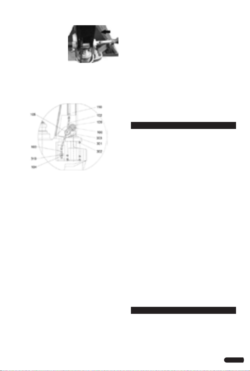
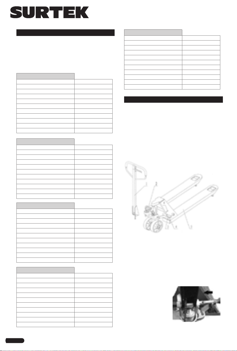
2. Let control handle to the ‘LOWER’ position,
then pass the adjusting nut, adjusting bolt
and chain through the hole of axle with your
hand (See fig. 3).
3. Press the draw-bar) down, take away the
pin(#2) (See Fig. 1).
4. Let the control handle on ‘RAISE’ position,
then raise the lever plate with the pin (#2)
and insert the adjusting bolt(103) into the
front slot of lever plate , note to keep the
adjusting nut on the under side of the lever
plate.
5. Use a hammer to tap another elastic pin into
the axle with hole. The draw-bar is now as-
sembled to the pump.
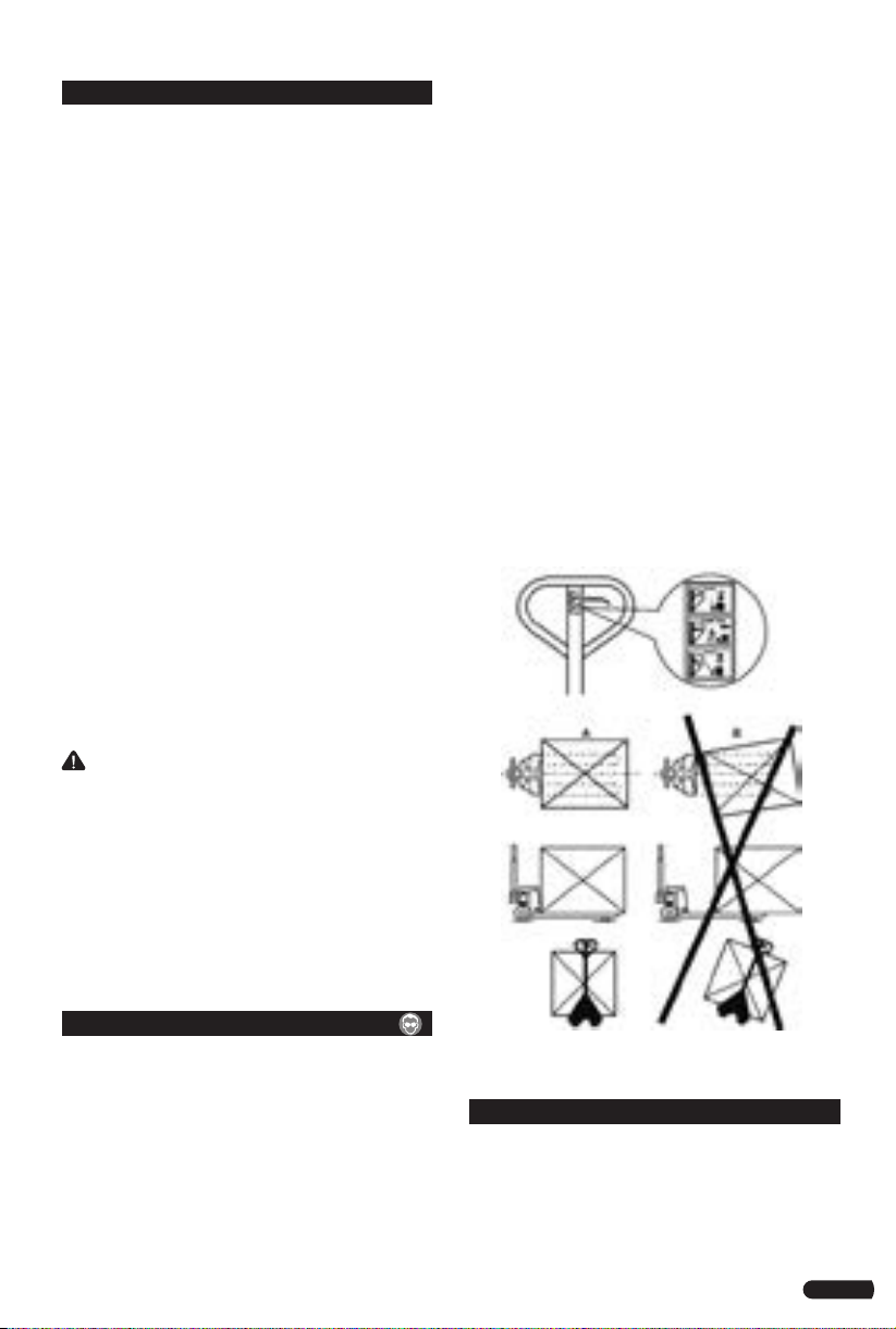
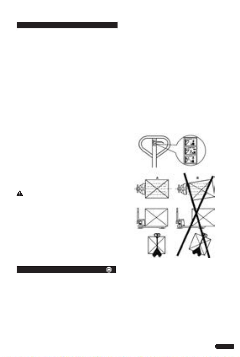
ADJUSTING RELEASE DEVICE
On the draw-bar of this pallet truck, you can
find the control handle which can be adjusted
in three positions:
1. Raise: handle down
2. Drive: handle in center position
3. Lower: handle up, the lever moves back
the drive position when released.
If however they have been changed, you can
adjust according to following step:
1. If the forks elevate while pumping in the
DRIVE position, turn the adjusting nut on the
adjusting bolt or screw clockwise until pump-
ing action does not raise the forks and the
DRIVE position functions properly.
2. If the forks descend while pumping in the
DRIVE position, turn the nut or screw counter-
clockwise until the forks do not lower.
3. If the forks do not descent when the control
handle is in the LOWER position, turn the
nut or screw clockwise until raising the con-
trol handle lowers the forks. Then check the
DRIVE position according to item 1 and 2 to
be sure the nut and screw is in the proper
position.
4. 3.4 If the forks do not elevate while pumping
in the RAISE position, turn the nut or screw
counter-clockwise until the forks elevate
while pumping in the RAISE position. Then
check the LOWER and DRIVE position accord-
ing to item 1, 2 and item 3.
MAINTENANCE
The pallet truck is largely maintenance-free.
1. OIL: Please check the oil level every six
months. The oil can be hydraulic oil: ISO
VG32, its viscosity should be 30cSt at 400 C,
total volume is about 0.4lt.
2. TO BANISH THE AIR: The air may come into
the hydraulic oil because of transportation or
pump in upset position. It can cause that the
forks do not elevate while pumping in the
RAISE position. The air can been removed in
the following way: let the control handle on
the LOWER position, then move the draw-bar
up and down for several times.
3. DAILY CHECK AND MAINTENANCE: Daily
check of the pallet truck can limit wear as
much as possible. Special attention should be
paid to the wheels, the axles, as thread, rags,
etc. It may block the wheels. The forks should
be unloaded and lowered in the lowest posi-
tion when the job is over.
4. LUBRICATION: All bearings and shafts are
provided with long-life grease at the factory.
You only need provide with long-life grease
at monthly intervals or after each time the
truck is cleaned thoroughly to the lubrication
points.
TROUBLESHOOTING
THE FORKS CAN NOT BE LIFTED UP THE
MAXIMUM HEIGHT.
Problem: The hydraulic oil is not enough.
Solution: Pour in the oil..
THE FORKS CAN NOT BE LIFTED UP.
Problem: Without hydraulic oil.
Solution: Fill in the oil.
Problem: The oil has impurities..
Solution: Change the oil.
Problem: The nut is too high, keep the pumping
valve open.
Solution: Adjust the nut or screw.
Problem: Air come into the hydraulic oil.
Solution: Banish the air.
Fig.3

10
ENGLISH•User's Manual
THE FORKS CAN NOT BE LOWERED.
Problem: The piston rod or pump is deformed
resulting from partial loading slanting to one
side or over-loading.
Solution: Replace the piston rod or pump.
Problem: The fork was kept in the high position
for long time with piston rod bared to arise in
rusting and jamming of the rod.
Solution: Keeping the fork in the lowest
position if not using, and pay more attention to
lubricate the rod.
Problem: The adjusting nut or screw is not in
correct position.
Solution: Adjust the nut or screw.
LEAKS.
Problem: Sealing parts worn or damaged.
Solution: Replace with the new one.
Problem: Some part cracked or worn into small.
Solution: Replace with the new one.
THE FORKS LOWERED WITHOUT THE RELEASE
VALVE WORKING.
Problem: The impurities in the oil cause the
release valve to be unable to close tight.
Solution: Replace with new oil.
Problem: Some parts of hydraulic system is
cracked or bored.
Solution: Inspect and replace the waste parts.
Problem: Air come into the oil.
Solution: Banish the air.
Problem: Sealing parts worn or damaged.
Solution: Replace with the new one.
Problem: The adjusting nut or screw is not in the
correct position.
Solution: Adjusting the nut or screw.

11
Notas / Notes

12
URREA HERRAMIENTAS PROFESIONALES S.A.
DE C.V. Warranties this product for a period of 1
years in its parts, components and manual labour
against any manufacture defect from the purchas-
ing date.
Purchase date: ____/____/____
Product:____________________
Brand:______________________
Model:______________________
______________________________
Distributor seal and signature
Sold and Imported by:
URREA HERRAMIENTAS PROFESIONALES S.A. DE
C.V. Carretera a El Castillo, km 11.5, C.P. 45680,
El Salto, Jalisco, México. R.F.C. UHP900402Q29.
Terms:
In order to make warranty effective you must pres-
ent the product along with the warranty properly
filled and signed to an authorized distributor or
service center.
Present the invoice or ticket with official registra-
tion info of the trade from where the product was
purchased. The guarantee is effective as of the date
of purchase stated on the invoice or ticket; or with
the distributor’s stamp (with delivery date in this
policy).
URREA HERRAMIENTAS PROFESIONALES S.A.
DE C.V. Will cover the transportation cost related
to the warranty.
This warranty is not applicable in the follow-
ing cases:
· When the product has not been used according to
normal conditions or natural wear of its parts.
· When the product has not been used according
with this user’s manual instructions.
· When the product has been fixed or modified by
unauthorized or unqualified person.
URREA HERRAMIENTAS PROFESIONALES S.A.
DE C.V. garantiza este producto por el termino de
1 años en sus piezas, componentes y mano de obra
contra cualquier defecto de fabricación a partir de
la fecha de entrega.
Fecha de venta: ____/____/____
Producto: ___________________
Marca: ______________________
Modelo: ____________________
______________________________
Sello y firma de distribuidor
Comercializado e Importado por:
URREA HERRAMIENTAS PROFESIONALES S.A. DE
C.V. Carretera a El Castillo, km 11.5, C.P. 45680,
El Salto, Jalisco, México. R.F.C. UHP900402Q29.
Condiciones:
Para hacer efectiva la garantía deberá presentar
el producto junto con la póliza de garantía debi-
damente firmada y sellada por el establecimiento
donde la adquirió, en cualquiera de los centros de
servicio autorizados.
Presentar la factura o ticket con datos fiscales del
comercio de donde se adquirió el producto. La ga-
rantía cuenta a partir de la fecha de la nota o factu-
ra de compra o el sello con fechador del distribuidor
(con fecha de entrega en esta póliza).
Los gastos de transportación que se deriven del
cumplimiento de la garantía serán cubiertos por:
URREA HERRAMIENTAS PROFESIONALES S.A.
DE C.V.
Esta garantía no será valida en los siguientes
casos:
· Cuando el producto haya sido utilizado en condi-
ciones distintas a las normales o al desgaste natural
de sus partes.
· Cuando el producto no haya sido operado de
acuerdo al instructivo de uso que lo acompaña.
· Cuando el producto haya sido alterado o reparado
por personas no autorizadas.
ESPAÑOL
PÓLIZA DE GARANTÍA
ENGLISH
WARRANT POLICY
This manual suits for next models
4
Table of contents
Languages: