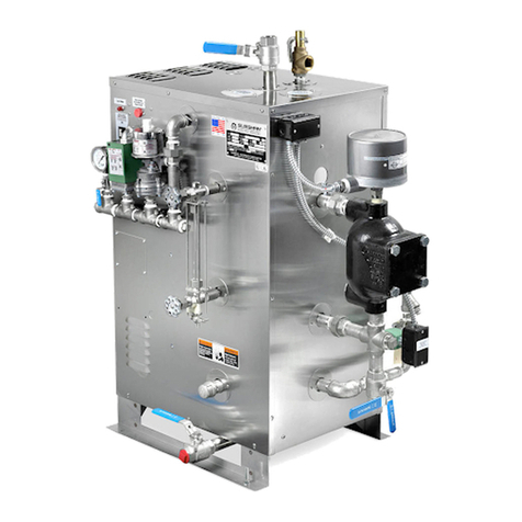
Before Installing your new elements be sure
the McDonnell Miller low water cut-off and aux. low water cutoff
(if supplied) is operating properly. The float chamber and lower
equalizer column of the MM control must be completely clear of
sludge or other foreign matter. Failure to do this may cause the
immediate burn-out of the new elements. If the unit is probe
equipped, check condition of the probes and isolator.
All elements are thoroughly checked before shipment. The manufac-
turer cannot be responsible for burn-outs caused by a faulty
low water cut-off.
The lower equalizer column can best be examined by breaking the
unions on either side and then visually and manually examining the
piping with your finger or probes to see if it is clear and clean.
1.
Disconnect boiler from electric power supply at main safety switch or fuse panel.
Then turn boiler switch to “OFF" position.
2.
Close water supply valve on incoming water supply line. Drain boiler completely of
water.
3.
Open boiler door to access heating element.
4.
Disconnect wire (electric) leads connecting element to main power system of boiler.
Again, note wire connections to facilitate re-assembly. Proceed to remove and discard
(6) bolts from flange.
IMPORTANT:
Note the wire connections to facilitate re-assembly (see wiring schematic).
Remove and discard six (5/16"-1 ) bolts from flange. Do not reuse these bolts.
5.
Thoroughly clean boiler flange of all foreign material. Be certain no part of old gasket
remains on flange.
6.
Apply "Slic-Tite" Gasket Compound (or equal) to both surfaces of new gasket supplied
with replacement element. Proceed to install element flange assembly with gasket
between boiler flange and element flange. In doing this, be careful to align flange holes
so element wire connection terminals on element assembly are in line with previously
disconnected wire leads to facilitate easy connections.
NOTE:
Observe markings on element flange. Install element marking “TOP” on top.
7.
Use only new element flange bolts. Tighten all (6) element flange bolts to a torque value
of 22 lb-ft each (see illustration).
.
Connect all wires to the terminals. Tighten all element terminals to a torque value of
20 lb-in each (see illustration). Make sure all wires are clean and bright to assure good
electrical contact.
9.
Check that the wires are correctly connected to the contactor terminals and are tight-
ened to the torque listed on the contactor. Make sure all wires are clean and bright to
assure good electrical contact.
10.
Open water valve to allow water supply to reach boiler feed mechanism.
11.
As boiler automatically refills, observe the new flange assembly for possible leaks.
If water is noticed, the bolts must be re-tightened. Before doing this, turn the boiler off
at the main fuse safety switch.
12.
When boiler reaches working pressure, check flange assembly again for leaks.
Follow maintenance instructions provided with the boiler.
ES 30A - ES36A - HP 30A Electric Steam Generator Installation, Operation and Maintenance Manual
_____________________________________________________________________________
7
Torque Values:
Element Flange Bolts 22 lb-ft
Element Terminals 20 lb-in
Contactor Terminals see Torque chart
For Illustrative Purposes Only.
Power wiring shown in approximate
factory-installed location
Torque
Wrench
Torque
Wrench
Torque
Wrench
READ INSTRUCTIONS COMPLETELY BEFORE STARTING WORK
Boiler with
McDonnell Miller
11⁄2
1 Steam Equalizing Pipe
Pump and Low Water Control
Normal Boiler Water Line
Cut-Off Level is Arrow Mark
Blowdown Valve
1 Water Equalizing Pipe
Element Replacement
TORQUE VALUES
Element Flange Bolts 22 lb-ft
Element Terminals 20 lb-in
Contactor Terminals Tighten to torque
specified on contactor
!CAUTION
!CAUTION


