PLUMBER’S INSTALLATION INSTRUCTIONS. PLEASE
READ CAREFULLY BEFORE INSTALLATION.
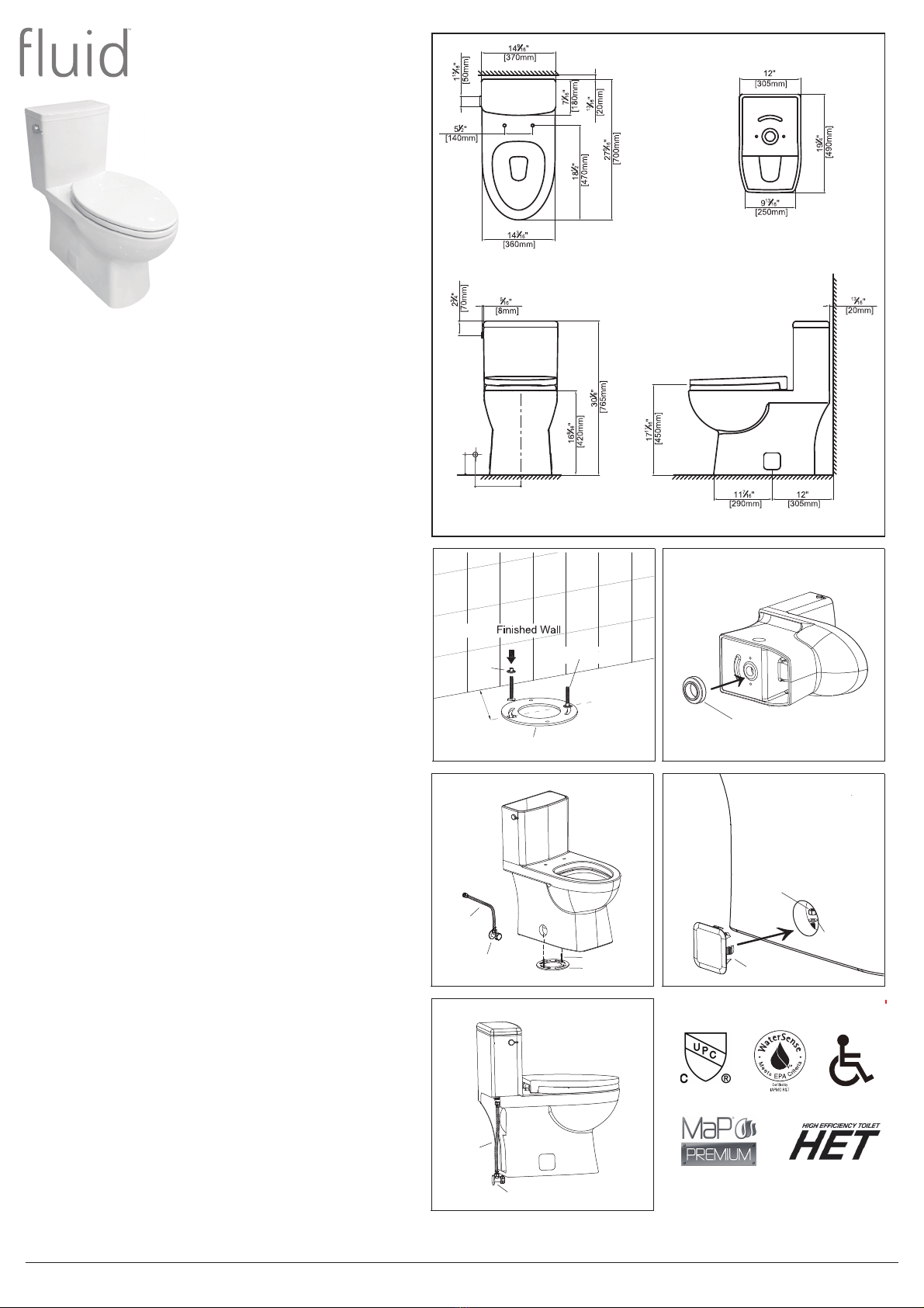
Rough in:
It is essential for the installation of the Quad Siphonic Rimless
One Piece Toilet that the closet flange must be accurately
set out from the finished wall as detailed in Fig.1.
Working Water Pressure:
USA & Canada: Recommended working water pressure is
20-80psi (140-550Kpa).
Installation Procedure:
1- Position closet bolts into closet flange (not supplied), as
detailed in Fig.1. Make sure two closet bolts are pointing
straight up and are directly across from each other.
4- Position and firmly place the supplied wax ring onto the
trapway, as detailed in Fig.2.
5- Accurately align the toilet over the closet bolts and flange
and lower into position as detailed in Fig. 3.
6- Secure the toilet by hand tightening nuts and metal
washers onto the closet bolts through the side opening.
Apply an additional 1/2 turn with a wrench tool for final
installatioin, as detailed in Fig. 4.
8-
Remove any excess silicone caulking.
9-
for leaks. Note: The tapered rubber seal and wing nut
assembled at the inlet valve connection end is a 3/8” hard
tube/pipe connection. Remove them if a braided toilet
supply line connector is used.
All measurements are subject to accepted manufacturing tolerances.
To ensure complete accuracy, please check actual product dimen-
sions before drilling for installation. The manufacturer reserves the
right to change specifications at any time without giving prior notification.
Date of Issue: Oct 2022
Vitreous China Dual Flush
High Efficiency (UHET)
For further information please visit our website
www.sustainablesolutions.com
3- Ensure that the area around the toilet bottom is clean and
free from building material.
7-
It is recommended that a bead of silicone caulking is
applied fully around base of the closet bowl.
Sustainable Solutions Vancouver BC + Ferndale WA
Quad Siphonic Rimless
1.28/0.8 gpf (4.8/3 lpf)
Easy Height & Elongated
One Piece Toilet with
Side Lever Handle
LH Lever FT160110W
RH Lever FT160110W-R
Connect the water supply line to toilet inlet valve
connection as detailed in Fig. 5 and check all connections
10-
Install the toilet seat according to the instructions included
with the seat.
Fig. 1 Fig. 2
Fig. 4Fig. 3
Install the side handle lever according to the instructions
included with the side lever.
11-
Cover the round holes on both sides of toilet with the
supplied square covers.
This product should be installed by a qualified plumber. Local authority,
Water Board, and Building Regulations may apply to the installation of
this product, and you should consult the appropriate bodies on these
requirements. Failure to comply may invalidate the product warranty.
Fig. 5
Location of
Angle Stop
216 mm
8-1/2”
140mm
5-1/2”
12-
Push side lever down firmly for a full flush and pull side
lever up for a reduced flush.
13-
Closet Bolt
Closet Flange
Wax Ring
12”
[305mm]
Water
Supply
Line
Angle Stop Valve Closet Bolt
Closet Flange
Water
Supply
Line
Angle Stop Valve
Square Cover
Nut
Metal Washer
Flange
Lock
Nut
2- Securely attach the two closet bolts onto the closet flange
using the supplied flange lock nuts.


