suter/ohlhorst System 515 User manual

suter/ohlhorst
Modular Loudspeaker Systems
Manual
revision 22
System 515
System 515/9
System 515/99
System 519
System 519/9
Signalprozessor 4.8
NetControl


suter/ohlhorst
Modular Loudspeaker Systems
READ THIS FIRST!
DO NOT HOT PLUG
THE SPEAKERS!
•Please make sure all amps are configured for the mains
voltage of your country (e.g. 230V, 115V).
•To avoid damaging the speakers and voiding your warranty
you have to ensure the following speaker connection
sequence:
1. Connect all XLR cables (1-6)
2. Connect all power cables
Disconnection of the cables needs to be done in reversed
order.
Never connect or disconnect a XLR cable of an already
powered amp since this might damage the speakers! (*)
•It is strongly recommended to not switch the loudspeaker
presets during high listening volumes.
(*) The reason for that is, because we want to have as few parts in the audio chain
as possible to ensure maximum transparency. Due to that, each of our speaker
chassis is directly connected to the amp.

suter/ohlhorst
Modular Loudspeaker Systems
Content
1. Introduction ................................................................................................................................6
2. System Setup ..............................................................................................................................7
2.1 Input Connection.................................................................................................................7
2.1.1 Analog connection .......................................................................................................7
2.1.2 Digital connection via AES/EBU ...................................................................................8
2.2 Output Connection..............................................................................................................9
2.2.1 System 515 ...................................................................................................................9
2.2.2 System 519 ................................................................................................................ 10
2.2.3 System 515/9 ............................................................................................................ 11
2.2.4 System 519/9 ............................................................................................................ 12
2.2.5 System 515/99 .......................................................................................................... 13
3. Signalprozessor........................................................................................................................ 14
3.1 Overview........................................................................................................................... 14
3.1.1 Front view ................................................................................................................. 14
3.1.2 Rear view................................................................................................................... 14
3.1.3 Bar LED Display.......................................................................................................... 15
3.1.4 Display and controls.................................................................................................. 15
3.2 Main Menu ....................................................................................................................... 15
3.2.1 Available Operations in the main menu ................................................................... 16
3.3 Load preset 'LOAD PRESET' .............................................................................................. 16
3.4Save preset 'STORE PRESET' ............................................................................................. 16
3.4.1 Edit preset name ....................................................................................................... 17
3.5 Mute ................................................................................................................................. 17
3.6 Menu navigation .............................................................................................................. 17
3.6.1 Channel Settings ....................................................................................................... 17
3.6.2 Select Input ............................................................................................................... 18
3.6.3 Info ............................................................................................................................ 18
3.6.4 AES-Mode.................................................................................................................. 18

suter/ohlhorst
Modular Loudspeaker Systems
3.6.5 EQ Settings ................................................................................................................ 19
3.6.6 Outsum...................................................................................................................... 19
3.6.7 Set IP-Address ........................................................................................................... 20
3.6.8 Special Functions....................................................................................................... 20
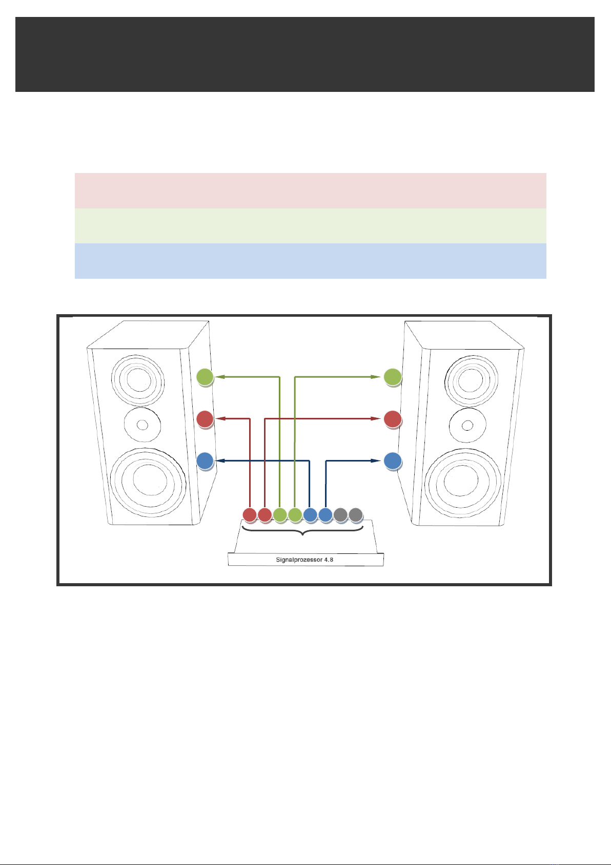
3.7 Diagrams........................................................................................................................... 21
3.7.1 Audio routing ............................................................................................................ 21
4. NetControl Software................................................................................................................ 22
4.1 Setup of Signalprozessor IP Address ................................................................................ 22
4.2 NetControl Interface ........................................................................................................ 24
4.2.1 Scan ........................................................................................................................... 24
4.2.2 Type in of IP Address................................................................................................. 24
4.2.3 Main Window............................................................................................................ 25
4.2.4 IN Input Window....................................................................................................... 26
4.2.5 IIR Input Filter window.............................................................................................. 26
4.2.6 Output window ......................................................................................................... 27
4.2.7 Limiter Window......................................................................................................... 28
4.2.8 Presets Window ........................................................................................................ 29
4.2.9 Loading and Saving Presets....................................................................................... 29
5. Specifications ........................................................................................................................... 31
5.1 Speaker Models................................................................................................................ 31
5.1.1 Dimensions and Weight ............................................................................................ 31
5.2 Amplification .................................................................................................................... 31
5.2.1 Specifications ............................................................................................................ 31
5.3 Signalprozessor................................................................................................................. 32
5.3.1 Audio ......................................................................................................................... 32
5.3.2 DSP ............................................................................................................................ 32
5.3.3 Display....................................................................................................................... 32
5.3.4 Network..................................................................................................................... 32
5.3.5 Dimensions and Weight ............................................................................................ 33
6. Warranty.................................................................................................................................. 34

- 6-
suter/ohlhorst
Modular Loudspeaker Systems
1. Introduction
The suter/ohlhorst system is a modular speaker system. It has been developed by the two
engineers Dan Suter (echochamber / Switzerland) and Jan Ohlhorst (finemastering / Germany).
Our approach was to listen and work with as much as possible different speaker chassis, speaker
chassis combinations in various cabinets (closed & ported) with different crossovers & settings in
various rooms. Additionally acoustical measurements have been performed for understanding
and verification.
The system is DSP-based which provides the possibility to tune it to the room and listeners taste.
It is also modular and can be easily extended with additional ways.

- 7-
suter/ohlhorst
Modular Loudspeaker Systems
2. System Setup
2.1 Input Connection
The input of the Signalprozessor can be connected as analog (left/right) or digital audio.
2.1.1 Analog connection
Connect the XLR output cable for left channel to input 1 and for right channel to input 2 of the
Signalprozessor as shown in the figure below.
Monitorcontroller
analog output
1
2
3
4
Inputs

- 8-
suter/ohlhorst
Modular Loudspeaker Systems
2.1.2 Digital connection via AES/EBU
The Signalprozessors digital input accepts digital Signals in the AES/EBU format (110ohm).
Connect the AES XLR cable of your digital Monitor-/Volumecontroller to the Input 2 of the
Signalprozessor as shown in the figure below.
1
2
3
4
Inputs
Monitorcontroller
digital output (AES/EBU)

- 9-
suter/ohlhorst
Modular Loudspeaker Systems
2.2 Output Connection
The amp(s) of each speaker model are directly connected to the Signalprozessors outputs. In the
following the connection of the XLR cables to various Systems is shown.
Please make sure to connect your System as shown in the figures to avoid damaging the
speakers.
2.2.1 System 515
Connect the XLR cables of the Signalprozessors analog outputs (1-4) to the corresponding inputs
of the speaker amp. Make sure to connect as follows:
•Outputs 1/2 are always used for the HIGH speaker chassis (tweeter), where output 1 is for
left and output 2 for the right speaker
•Outputs 3/4 are always used for the MID speaker chassis, where output 3 is for left and
output 4 for the right speaker
•Outputs 5-8 are unused in that configuration
outputs
MID MID
HIGHHIGH
1
2
3
4
5
6
7
8
1/2
3/4
1/2
3/4

- 10-
suter/ohlhorst
Modular Loudspeaker Systems
2.2.2 System 519
Connect the XLR cables of the Signalprozessors analog outputs (1-6) to the corresponding inputs
of the speaker amp. Make sure to connect as follows:
•Outputs 1/2 are always used for the HIGH speaker chassis (tweeter), where output 1 is for
left and output 2 for the right speaker
•Outputs 3/4 are always used for the MID speaker chassis, where output 3 is for left and
output 4 for the right speaker
•Outputs 5/6 are always used for the LOW speakers chassis (bass chassis), where output 5
is for left and output 6 for the right speaker
•Outputs 7/8 are unused in that configuration
outputs
MID MID
HIGHHIGH
LOW LOW
1
2
3
4
5
6
7
8
1/2
3/4
5/6
1/2
3/4
5/6

- 11-
suter/ohlhorst
Modular Loudspeaker Systems
2.2.3 System 515/9
Connect the XLR cables of the Signalprozessors analog outputs (1-6) to the corresponding inputs
of the speaker amp. Make sure to connect as follows:
•Outputs 1/2 are always used for the HIGH speaker chassis (tweeter), where output 1 is for
left and output 2 for the right speaker
•Outputs 3/4 are always used for the MID speaker chassis, where output 3 is for left and
output 4 for the right speaker
•Outputs 5/6 are always used for the LOW speakers chassis (bass chassis), where output 5
is for left and output 6 for the right speaker
•Outputs 7/8 are unused in that configuration
outputs
MID MID
HIGHHIGH
LOW LOW
1
2
3
4
5
6
7
8
1/2
3/4
5/6
1/2
3/4
5/6

- 12-
suter/ohlhorst
Modular Loudspeaker Systems
2.2.4 System 519/9
Connect the XLR cables of the Signalprozessors analog outputs (1-6) to the corresponding inputs
of the speaker amp. Make sure to connect as follows:
•Outputs 1/2 are always used for the HIGH speaker chassis (tweeter), where output 1 is for
left and output 2 for the right speaker
•Outputs 3/4 are always used for the MID speaker chassis, where output 3 is for left and
output 4 for the right speaker
•Outputs 5/6 are always used for the LOW speakers chassis (bass chassis), where output 5
is for left and output 6 for the right speaker
Please use our XLR Y-cable to split the Signal of outputs 5/6
•Outputs 7/8 are unused in that configuration
outputs
MID MID
HIGHHIGH
LOW LOW
1
2
3
4
5
6
7
8
1/2
3/4
5/6
1/2
3/4
5/6
LOW LOW
5/6
5/6

- 13-
suter/ohlhorst
Modular Loudspeaker Systems
2.2.5 System 515/99
Connect the XLR cables of the Signalprozessors analog outputs (1-6) to the corresponding inputs
of the speaker amp. Make sure to connect as follows:
•Outputs 1/2 are always used for the HIGH speaker chassis (tweeter), where output 1 is for
left and output 2 for the right speaker
•Outputs 3/4 are always used for the MID speaker chassis, where output 3 is for left and
output 4 for the right speaker
•Outputs 5/6 are always used for the LOW speakers chassis (bass chassis), where output 5
is for left and output 6 for the right speaker
Please use our XLR Y-cable to split the Signal of outputs 5/6
•Outputs 7/8 are unused in that configuration
outputs
MID MID
HIGHHIGH
LOW LOW
1
2
3
4
5
6
7
8
1/2
3/4
5/6
1/2
3/4
5/6
LOW LOW
5/6
5/6

- 14-
suter/ohlhorst
Modular Loudspeaker Systems
3. Signalprozessor
The Signalprozessor is the central control of the suter/ohlhorst loudspeaker systems. It
implements the digital crossovers for the various system configurations including the driver
adjustments. It is also used to fine-tune the system to the room and to the listeners taste.
3.1 Overview
3.1.1 Front view
The Signalprozessor hardware controller gives you a nice overview of output levels, currently
selected preset etc.
3.1.2 Rear view
All cable connection is done on the rear side of the Signalprozessor. Beside the power connector,
the already mentioned Ethernet connector is available. Furthermore you have XLR jackets for the
outputs and inputs.
Please note, that the power cable might have a securing. In that case you need to slide back the
red plastic pin on the cable before pulling it out.
Power
connector
Ethernet
connector
Outputs 1-8:
to speaker amps
Input 1-4:
from monitor
controller
MID
HIGH
LOW
5
6
3
4
1
2

- 15-
suter/ohlhorst
Modular Loudspeaker Systems
3.1.3 Bar LED Display
The Front Bar LED Display gives a good overview on the Signalprozessors input and output signal
level. In the output section you can additionally mute each output by pressing the corresponding
mute button.
3.1.4 Display and controls
The Display typically shows the loaded preset. With the various buttons and the Encoder all
settings can be done. Of course we highly recommend to use the NetControl software to make
all adjustments as described in chapter 4.
3.2 Main Menu
In the main menu the device name, currently loaded preset and network information are
displayed.
Outputs 1-8 signal
level LEDs and
mute buttons
Input 1-4 signal
level LEDs
Selection buttons
A-D
Menu/ESC,
Load and Store
button
Encoder

- 16-
suter/ohlhorst
Modular Loudspeaker Systems
3.2.1 Available Operations in the main menu
Menu / ESC: Switch to menu navigation
Load:Open the menu 'LOAD-PRESET'. (see chapter 4)
Store: Open the menu 'STORE-PRESET'. (see chapter 8)
A 'IN1': Press and hold to see the routing and name for Input 1
B 'IN2': Press and hold to see the routing and name for Input 2
C 'IN3': Press and hold to see the routing and name for Input 3
C 'IN4': Press and hold to see the routing and name for Input 4
3.3 Load preset 'LOAD PRESET'
Encoder:
Select preset
A 'LOAD':
Load preset
D 'EXIT':
Exit menu without modification
Menu/ESC:
Exit menu without modification
It is strongly recommended to not switch the loudspeaker presets during high listening
volumes.
3.4 Save preset 'STORE PRESET'
Encoder:
Select memory (1 – 24)
A 'STORE':
Save preset with the current name in the selected memory
B 'EDIT':
Edit preset name
D 'EXIT':
Exit menu without modification
Menu/ESC:
Exit menu without modification
Loaded
preset
Preset
number
Last number
of IP address
Connected
to PC

- 17-
suter/ohlhorst
Modular Loudspeaker Systems
3.4.1 Edit preset name
Encoder:
Select number at the current cursor position
A '<-':
Move cursor left
B '->':
Move cursor right
C 'CLR':
Clear display
D 'STORE':
Save preset with the entered name in the previously selected memory
Menu/ESC:
Exit the menu without modification and return to storage space selection
3.5 Mute
Pressing and holding the keys “ESC/Menü”, “Load” or “Store” for a longer time will switch to
one of the following mute menus. In the mute menus the keys A-Dwill mute or unmute the
corresponding channel.
Mute menus:
Menu/ESC:
MUTE IN 1-4
Load:
MUTE OUT 1-4
Store:
MUTE OUT 5-8
It is also possible to mute or unmute the output channels with the keys located under the output
bar-graph.
3.6 Menu navigation
Pressing the “Menu / ESC” key and turning the encoder selects between the following menus:
CHANNEL SETTINGS
Chapter 3.6.1
SELECT INPUT
Chapter 3.6.2
INFO
Chapter 3.6.3
AES-MODE
Chapter 3.6.4
EQ SETTINGS
Chapter 3.6.5
OUTSUM
Chapter 3.6.6
SET IP-ADDRESS
Chapter 3.6.7
3.6.1 Channel Settings
In the CHANNEL SETTINGS menu the following values can be set for each input or output
channel:
Phase
0° or 180°
Delay
in 0,01 ms steps

- 18-
suter/ohlhorst
Modular Loudspeaker Systems
Gain
in 0,1 dB steps
Available operations in CHANNEL SETTINGS
A + Encoder:
Select channel for editing (IN 1–4 / OUT 1–8)
B + Encoder:
Adjust the Phase 0° / 180°
C + Encoder:
Adjust the channel delay in 0,01 ms steps.
D + Encoder:
Adjust the gain in 0,1 dB steps
Load / Store:
Copy 'n Paste the channel settings
Menu/ESC:
Back to main menu
Pressing the Encoder while turning sets the step size to 10
Copy & Paste
With the keys Load and Store the channel settings could be copied and pasted to another
channel.
Proceed as follows:
•Adjust the selected channels as desired
•Press the 'Load' key
•Select the channel for the settings to be copied at
•Press the 'Store' key
The copied settings are now applied to the selected channel.
3.6.2 Select Input
This menu enables selecting between AES and analog inputs.
To change between the inputs press and hold the “A” key and turn the encoder.
3.6.3 Info
This menu page delivers following information:
•Device Type
•Device Name
•Serial-number
•Firmware-version
3.6.4 AES-Mode
On this page information about the connected AES signals is displayed:
•The sample-rate or “UNLOCK” if no AES signal is detected
•The AES format

- 19-
suter/ohlhorst
Modular Loudspeaker Systems
3.6.5 EQ Settings
Here filter settings can be edited for each band available for the input and output channels.
A + Encoder:
Select channel for editing (IN 1-4 / OUT 1-8)
B + Encoder:
Select EQ band for editing
-
Inputs: EQ band 1-15
- Outputs: EQ band 1-10
C + Encoder:
Select the filter type.
D 'EDIT':
Opens the settings menu of the selected EQ band
Load / Store:
Copy 'n Paste of the channel settings
Menu/ESC:
Back to main menu
Pressing the Encoder while turning sets the step size to 10
Available filter typ
es
The following filter type can be selected:
•OFF no filter active
•Peak Peak filter
•HP High-Pass
•LP Low-Pass
•H-Shelf High-Shelf
•L-Shelf Low-Shelf
Copy & Paste
To use the copy 'n paste for the EQ settings proceed as follows.
•Adjust the settings for the selected channel as desired
•Press the 'Load' key
•Select the channel for the settings to be copied at
•Press the 'Store' key
The copied settings are now applied to the selected channel.
3.6.6 Outsum
An individual input mix to each output channel can be assigned. To assign a mix use the follow-
ing keys.
key A + Encoder:
Selecting the output channel to be edited (OUT 1-8)
key B:
Move cursor left
key C:
Move cursor right
key D:
Enable or disable input
Load / Store:
Copy 'n Paste of the input assignment (see chapter 7.1.2)
Menü/ESC:
Back to main menu

- 20-
suter/ohlhorst
Modular Loudspeaker Systems
Pressing the Encoder while turning sets the step size to 10
Copy & Paste
To use the copy 'n paste for the outsum settings proceed as follows.
•Set the input assignment of the selected output as desired
•Press the 'Load' key
•Select the output for the settings to be copied at
•Press the 'Store' key
The copied settings are now applied to the selected channel.
3.6.7 Set IP-Address
The MAC address of the device is displayed and the IP address could be set.
A change to the IP address will not take effect until the device is reb
oo
ted. Please refer to
section 4.1 to find out which IP address is appropriate in your case / for your network.
To edit the IP-Address use the following keys:
A + Encoder:
Setting of first IP-Octet
B + Encoder:
Setting of second IP-Octet
C + Encoder:
Setting of third IP-Octet
D + Encoder:
Setting of fourth IP-Octet
Load / Store:
without function
Menu/ESC:
Back to main view
Pressing the Encoder while turning sets the step size to 10
3.6.8 Special Functions
Display LOCK:
To lock the display press and hold the encoder for 3 seconds and press
a
dditionally the A key to lock the display controls. Press keys Menu/ESC
o
r A to return to the main menu. If the display is locked pressing one of
the
display keys will show the Unlock menu.
T
he mute keys under the output bar graph are still working
Display UNLOCK:
To unlock the display set the code to '12345' by turning the encoder and
press the D 'SET'.
Clear Group Param:
To remove group parameters set by the PC software press and hold the
e
ncoder for 3 seconds and press additionally the B key.
Clear All Param:
To set all parameters to their default setting press and hold the encoder
f
or 3 seconds and press additionally the C key.
This manual suits for next models
6
Table of contents