5
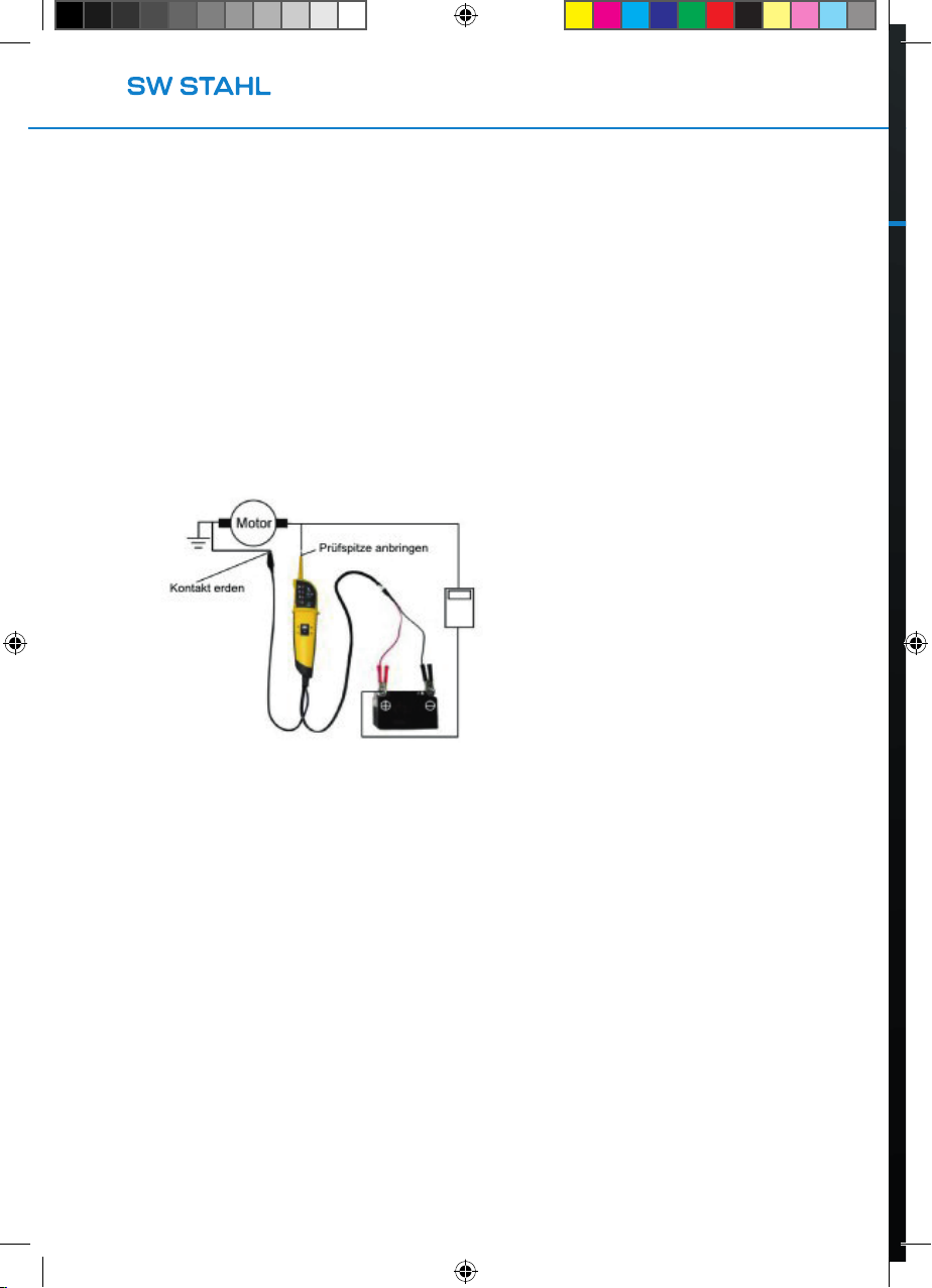
AKTIVIERUNG AUSGEBAUTER KFZ KOMPONENTEN
Mit Hilfe der Prüfspitze als Erdung können Komponenten aktiviert werden, die aus dem
Stromkreis eines Kfz ausgebaut worden sind. So können Scheinwerfer, Lüfter,
Einspritzpumpen etc. geprüft werden. Befolgen Sie dabei die folgenden Hinweise:
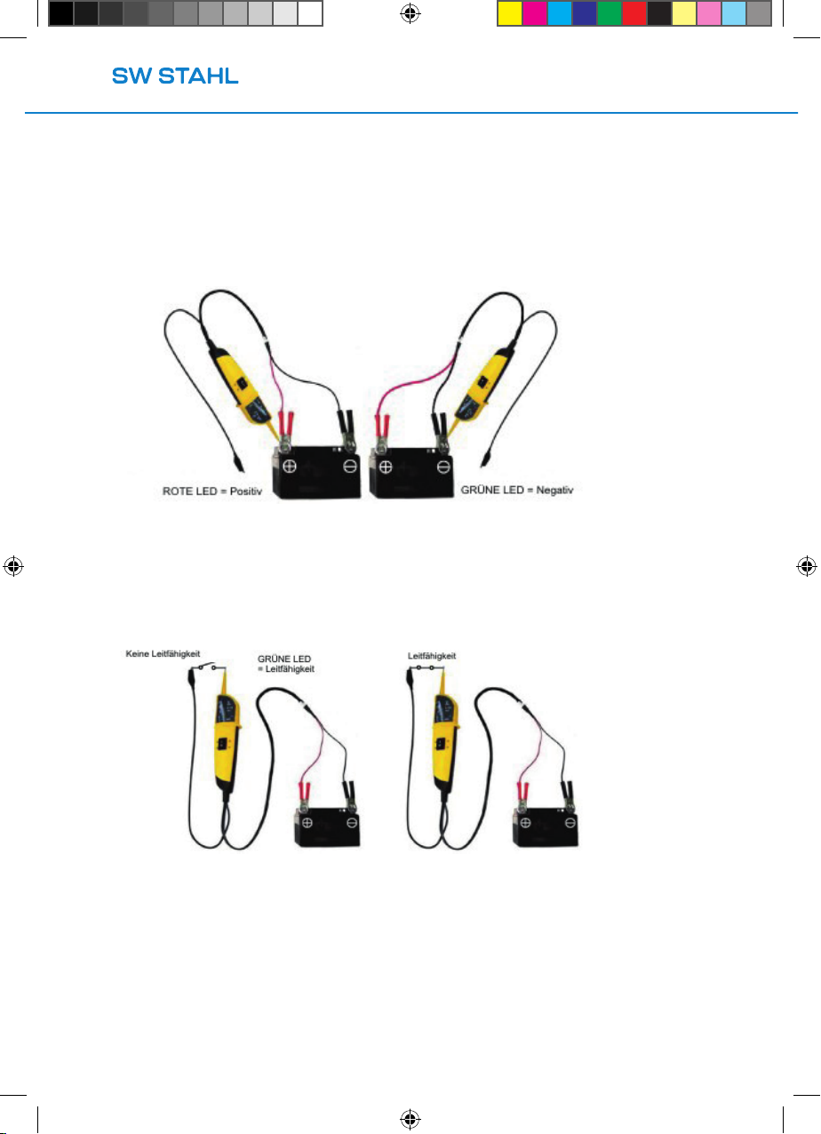
1. Berühren Sie den Minuspol der ausgebauten Komponente mit dem Erdungskabel.
2. Nun berühren Sie mit der Prüfspitze den Pluspol der Komponente. Wenn die
GRÜNE LED leuchtet, besteht eine Leitfähigkeit.
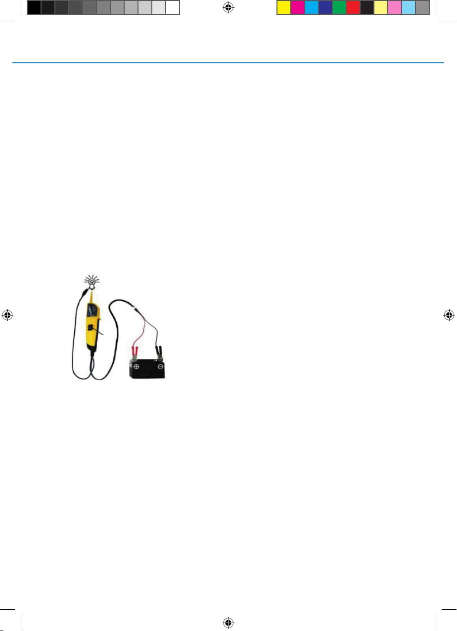
3. Bewegen Sie den Polaritätsschaltervorwärts und lassen Sie ihn direkt wieder los.
Wenn die LED jetzt von GRÜN zu ROTwechselt, fahren Sie mit dem Test fort. Sollte
die ROTE LED nicht erleuchten, ist der Multitesterwahrscheinlich überlastet oder die
Schutzsicherung ist aufgesprungen. Dies kann folgende Ursachen haben:
•Die ausgebaute Komponente hat einen Kurzschluss oderwurde direkt geerdet.
•Die ausgebaute Komponente ist ein Hochspannungsgerät.
Wenn die Schutzsicherung gesprungen ist, kann das Gerät erst nach 60 Sekunden wieder in Betrieb
genommen werden. Bis dahin hat sich die Sicherung regeneriert.
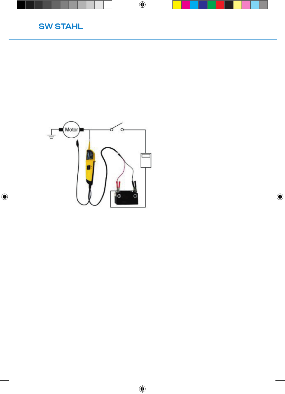
AKTIVIERUNG AUSGEBAUTER KOMPONENTEN
MIT POSITIVER SPANNUNG
Während eines Tests, kann das Gerät verwendet werden, um der Komponente eine positive Spannung
zuzuführen. Befolgen Sie hierzu die Schritte:
1. Berühren Sie mit der Prüfspitze den Pluspol der Komponente. Wenn die GRÜNE LED aueuchtet,
wird Leitfähigkeit angezeigt.
2. Bewegen Sie nun den Polaritätsschaltervorwärts und lassen Sie ihn direkt wieder los.Wenn die
LED nun von GRÜN zu ROT wechselt, fahren Sie mit dem Test fort. Sollte die ROTE LED nicht er-
leuchten, ist der Multitesterwahrscheinlich überlastet oder die Schutzsicherung ist
aufgesprungen.
Dies kann folgende Ursachen haben:
•Die ausgebaute Komponente hat einen Kurzschluss oderwurde direkt geerdet/an
einen Minuspol angeschlossen.
•Die ausgebaute Komponente ist ein Hochspannungsgerät.
32255L_manual_75030_de_en_fr_roh.indd 532255L_manual_75030_de_en_fr_roh.indd 5 14.12.20 17:4314.12.20 17:43