Swagelok MS-HTB-2 User manual

Hand Tube
Bender Manual
www.swagelok.com

2

3
Contents
Introduction ........................... 4
Tubing Data ............................ 4
Tubing Installation ..................... 6
Product Information ................... 7
Vise Clamp Block ...................... 8
Bend Layout ........................... 9
Using the Bender ...................... 12
Making Bends ......................... 15
Reverse Bends ........................ 18
Springback ............................ 19
Determining Changes in Plane and
Direction ............................... 20
Adjustment (Gain) Calculations ....... 21
Troubleshooting ....................... 24
Replacement Parts .................... 26

4
Introduction
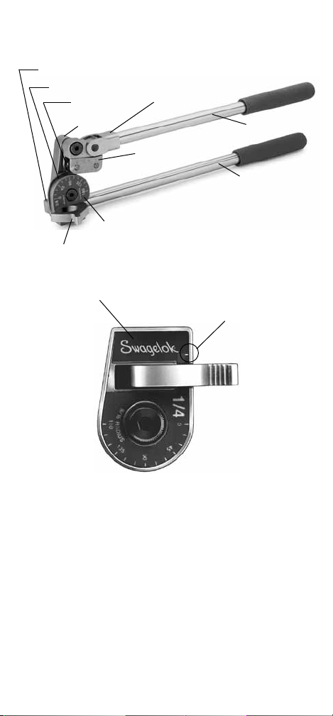
Swagelok®hand tube benders provide consistent,
high‑quality bends in tubing made from most materials
used with Swagelok tube ttings.
Read this manual before using the hand tube bender.
Tubing Data
■ The Swagelok hand tube bender bends 1/8,
1/4, 5/16, 3/8, and 1/2 in., and 3, 6, 8, 10, and 12
mm outside diameter tubing in a variety of wall
thicknesses.
■ Tubing should be free of scratches and suitable for
bending.
Suggested Tubing Ordering Information
Fractional Tubing
High‑quality, soft‑annealed, seamless carbon steel
hydraulic tubing ASTM A179 or equivalent. Hardness
72 HRB (130 HV) or less.
Fully annealed, high‑quality (Type 304, 316 etc.)
(seamless or welded and drawn) stainless steel
hydraulic tubing ASTM A269 or A213, or equivalent.
Hardness 90 HRB (200 HV or less).
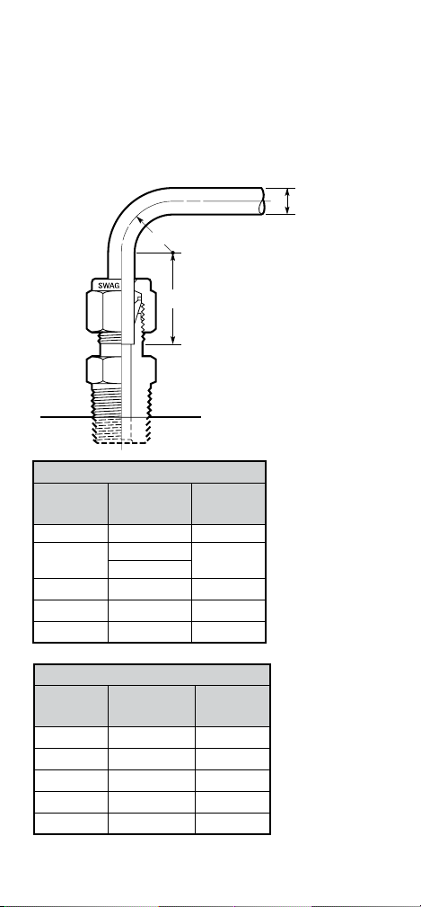
Tube
OD
Approx
Bend
Radius
Carbon Steel
Wall Thickness
Min/Max
Stainless Steel
Wall Thickness
Min/Max
Dimensions, in.
1/8 9/16 0.028/0.035
1/4 9/16 0.028/0.065
3/4 0.028/0.065
5/16 15/16 0.035/0.065
3/8 15/16 0.035/0.065 0.035/0.083
1/2 1 1/2 0.035/0.083

5
Metric Tubing
High‑quality, soft‑annealed, carbon steel hydraulic
tubing DIN2391 or equivalent. Hardness 130 HV (72
HRB) or less.
Fully annealed, high‑quality (Type 304, 316 etc.)
stainless steel tubing EN ISO 1127 or equivalent.
Hardness 200 HV (90 HRB) or less.
Tube
OD
Approx
Bend
Radius
Carbon Steel
Wall Thickness
Min/Max
Stainless Steel
Wall Thickness
Min/Max
Dimensions, mm
315 0.8/1.0 0.8/0.8
615 0.8/1.5
824 1.0/1.5
10 24 1.0/1.5 1.0/2.0
12 38 1.0/2.2 1.0/2.0

6
Tubing Installation
Properly selected tubing, combined with quality
Swagelok tube fittings, can provide leak‑tight
systems.
When installing fittings near tube bends, there must
be a sufficient length of straight tubing to allow the
tube to be bottomed in the Swagelok tube fitting:
L
T
R
Metric, mm
T
Tube OD
R
Bend Radius L
3 15 19
6 15 21
8 24 23
10 24 25
12 38 31
Fractional, in.
T
Tube OD
R
Bend Radius L
1/8 9/16 23/32
1/4 9/16 13/16
3/4
5/16 15/16 7/8
3/8 15/16 15/16
1/2 1 1/2 1 3/16
TTube OD
LRequired straight tube
length (see table)
(corresponds to straight
tube length mark on hand
bender.)
RRadius of tubing bend

7
Product Information
Clevis
Link
Roll dies
Bender die
Vise clamp block
Name plate
Tube latch
Roll support
Long handle
Short handle
Name plate Straight tube
length mark

8
Vise Clamp Block
The Swagelok hand tube bender features a vise
clamp block which allows the bender to be clamped
in a vise. This feature is helpful when bending tube of
a hard material or heavy wall thickness, or long pieces
of tubing that need to be supported.

9
Bend Layout
This bender can be used to form single, offset, and
other bends. This section contains information for
measuring and marking the tube prior to bending.
Note: Make all marks 360° around the tube.
The Measure-Bend Method
1. Estimate the overall length of tubing required by
adding the length of all the sections together.
2. Place a reference mark at the end of the tube
from which you are beginning the measurement.
3. Measure from the reference mark and make a
bend mark on the tube at a distance equal to
the desired bend length. This mark indicates the
vertex of the bend.
4. See Using the Bender, page 12, to bend the
tube.
5. For additional bends, use the vertex of the
previous bend as the reference mark, repeat
steps 3 and 4 for the next bend. (The vertex
is where the center lines of the two legs of the
angle intersect.)
An example appears on the next page.

10
Example of the measure‑bend method:
A 90° bend 4 inches from the reference mark followed
by a 45° bend with 4 inches between bends.
1. Place a reference mark at the end of the tube
from which you are beginning the measurements.
2. Measure 4 in. from the reference mark and make
a bend mark to indicate the rst desired bend
length.
3. Bend the tube 90° as described in Using the
Bender, page 12.
4. Make a second bend mark 4 in. from the vertex
of the 90° bend, away from the reference mark.
5. Place a directional mark over the bend mark
to indicate the outside, or heel, of the 45° bend.
This will help ensure the bend is made in the
intended direction.
6. Bend the tube 45° as described in Using the
Bender, page 12.
Directional mark
Second 90 Bend.eps
4 in.
Vertex
45°
Vertex
Reference
mark
4 in.

11
Offset Bend Formula
The purpose of an offset bend is to change the center
line of the run, typically to avoid an obstruction. To
determine the length of offset, select the offset angle
(E). Then, multiply the offset dimension (O) by the
offset bend allowance (A).
L = O A
Use the offset calculation as the distance between
the bend marks described in Bend Layout.
Offset Bend
Angle (E)
Offset Bend
Allowance (A)
22 1/22.613
302.000
451.414
601.15 4
Example
Offset bend angle (E) 45°
Offset dimension (O) 6.75 in.
6.75 1.414 = 9.55 in., or approximately 9 9/16 in.
C
C
O
LE
C
C
6.75 in.
9 9/16 in. 45°

12
3. Place the tube in the groove of the bender die
with the reference mark to the left of the tube
latch.
4. Close the tube latch over the tube just enough
to hold the tube in place. This restricts movement
of the tube during initial positioning but still
allows for additional alignment.
Short handle
Bender die
Tube latch
Using the Bender
1. Swing the short handle up so it is above the
bender die.
2. Open the tube latch.
Bender die
Reference mark
Tube latch

13
5. Carefully lower the short handle until the roll
dies rest gently on the tube while keeping the
link straight and parallel to the long handle.
Note: Premature bending may occur if the link
is not straight and parallel to the long
handle.
6. Align the zero on the roll support with the zero
on the name plate.
Short handle
Long handle
Reference
mark
Link
Roll dies
(one is hidden by link)
Shown aligned for a 90bend.
Note: View shown is from the back of the bender.
Name plate
Roll support
Reference
mark Bend mark

14
8. Push the tube latch rmly over the tube to
secure the tube in the bender die.
Note: Excessive pressure on the tube latch may
damage soft tubing.
7. Align the bend mark with the mark on the roll
support that corresponds to the bend angle.
Tube
latch
Bender
die
Note: View the marks on the hand tube bender
as a 0 to 90scale when bending other
angles.
153060759045

15
2. After completing the bend, swing the short
handle up and away from the tube.
1. Slowly push the short handle down until the 0
on the roll support reaches the desired degree
mark on the name plate.
Note: Be aware of springback, described on
page 19.
Making Bends
Bends 90° or Less
3. Pull the tube latch off the tube and remove the
tube from the bender groove.
Short handle
Roll support
Name plate
Short handle
Tube latch

16
Bends Greater than 90°
The right‑angle design of the Swagelok hand tube
bender offers maximum leverage when making
bends. The bender’s unique design lets you continue
using right angle leverage for bends greater than 90°.
1. Slowly push the short handle down until the 0
on the roll support reaches approximately 90
on the name plate.
2. Loosen the short handle from the clevis until
the short handle will swing without moving the
roll support.
Short handle
Roll support
Name plate
Short handle
Roll support
Clevis

17
3. Swing the short handle up until it is slightly
above perpendicular to the long handle.
4. Retighten the short handle. This will provide
continuous right‑angle leverage for the rest of the
bend.
5. Continue the bend until the 0 on the roll support
reaches the desired degree mark on the name
plate.
6. After completing the bend, swing the short
handle away, pausing when the 0 on the roll
support reaches approximately 90. Loosen the
short handle, move it until parallel with the long
handle, then retighten the short handle.
7. Move the short handle up and away from the
tube.
8. Pull the tube latch off the tube and remove the
tube from the bender groove.
Long handle Short handle
Roll support
Name plate

18
Reverse Bends
The Measure-Bend Method
Sometimes a multiple bend layout will require that a
bend be made in reverse. A reverse bend is made with
the reference mark to the right of the tube latch.
1. Align the bend mark with the marks on the roll
support as follows:
■90bends line up under the R mark
■For other bend angles, treat the marks
between 0 and R as an approximate 0 to 90
scale.
Shown aligned for a 90reverse bend.
2. Bend the tube as described in Making Bends,
page 15.
Tube
latch
Reference
mark
Bend
mark

19
All tubing will exhibit springback after a bend has
been completed. The amount of springback depends
on the bend angle, bend radius, tubing material, and
wall thickness.
Experience will help you predict the amount of
springback. Expect to allow 1 to 3° of compensation.
Note : Verify the bend angle using a template,
protractor or against a known angle to ensure
the desired bend angle has been achieved.
Springback
Note: Do not bend all the way to the bend mark
when bending softer tubing such as copper or
aluminum.
1 to 3°

20
Determining Changes in
Plane and Direction
When making multiple bends on a single piece of
tube, make sure the bend is made in the correct
direction.
For bends in the opposite direction of the previous
bend, align the tube with the raised short handle
(plane A).
For bends in the same direction as the previous bend,
align the tube parallel to the long handle (plane B).
Plane A
Plane A
Short handle
Tube
Plane B
Plane A
Plane B
Plane A
Long handle
Tube
This manual suits for next models
10
Table of contents
Other Swagelok Construction Equipment manuals