M100 Power Supply
2 ©1999 Swagelok Company, all rights reserved
August 2001
Installation
Tools and Accessory Requirements
You need the following tools and accessories to install
and operate your SWS.
Tool/Accessory Included? Provided with
Hex Wrenches (0.050 in. to 5/32 in.) Yes Weld Head
Electrode Package Yes Weld Head
Arc Gap Gage Yes Weld Head
Flat Blade Screw Driver Yes Weld Head
Centering Gage Yes Fixture Block
Quick-Connect Stem Yes Power Supply
Secondary Solenoid Bypass Plug Yes Power Supply
Dial/Digital Calipers or Micrometer No -
Purge Connector(s) No -
Shielding/Purge Gas Lines ①No -
Shielding/Purge gas Source②No -
Pressure Regulator No -
Internal Purge Gas Flow Meter No -
Shielding Gas Flow Meter No -
Internal Pressure Gage No -
①All lines used for shielding/purge gas should be the low moisture
absorption type.
②A compressed gas bottle or liquid Dewar source can be used. Argon
is the gas most frequently used.
Note:
The Series 40 weld head does not
include an arc gap gage, centering
gage, or electrode package.
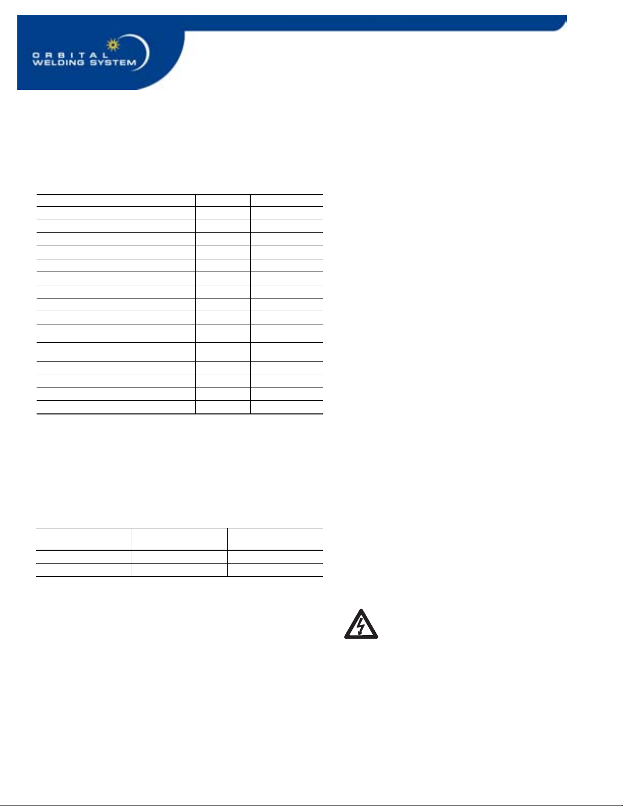
Electrical Requirements
Table 1 Power Supply Electrical Requirements
Power Supply
Model
Voltage
Requirement
Service Current
SWS-M100-1 115 V*(ac) 20 A
SWS-M100-2 230 V (ac) 15 A
* If the input voltage is 100 V or less, the output power capabilities
may be reduced.
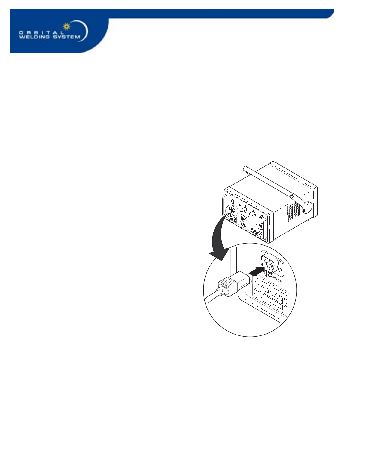
Follow the electrical system guidelines below for power
supply installation.
• All wiring and related components must be
installed according to local code and National
Electrical Code.
• The power supply must be grounded.
• A dedicated electrical circuit may be desired due
to current need.
WARNING!
THE POWER SUPPLY MUST
BE GROUNDED. IF IT IS NOT
GROUNDED, ELECTRICAL
SHOCK CAN OCCUR.