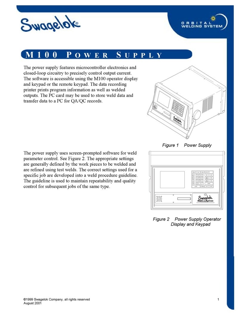
Swagelok M200 User manual

www.swagelok.com
Power Supply
User’s Manual
This manual contains important information for the safe
and effective operation of the Swagelok®Welding System
M200 power supply. Users should read and understand its
contents before operating the M200 power supply.

2M200 Power Supply User’s Manual

M200 Power Supply User’s Manual 3
Contents
Safety . . . . . . . . . . . . . . . . . . . . . . . . . . . . 5
Safety Summary . . . . . . . . . . . . . . . . . . . . . 5
Signal Words and Safety Alert Symbols
Used in this Manual . . . . . . . . . . . . . . . . . 5
M200 Power Supply Warning Label . . . . . . . . . . . 10
Referenced Documents . . . . . . . . . . . . . . . . . 11
Installation and Setup . . . . . . . . . . . . . . . . . . . 13
Description . . . . . . . . . . . . . . . . . . . . . . . . 14
Unpacking the M200 Power Supply . . . . . . . . . . . 16
Registration Information . . . . . . . . . . . . . . . . . 17
Tools and Accessories Required . . . . . . . . . . . 18
Electrical Requirements . . . . . . . . . . . . . . . 18
Setting up the M200 Power Supply . . . . . . . . . . . 19
Installing the Weld Head . . . . . . . . . . . . . . . . . 20
Setting Up the Gas Supply System . . . . . . . . . . . 21
Typical OD Shield / ID Purge Gas Supply System . . 21
Powering On the M200 Power Supply for the First Time 22
Powering Off the M200 Power Supply . . . . . . . . . . 22
Restarting the M200 Power Supply . . . . . . . . . . . 22
Using the Touch Screen . . . . . . . . . . . . . . . . . 23
User Interface . . . . . . . . . . . . . . . . . . . . 23
Operation . . . . . . . . . . . . . . . . . . . . . . . . . . 25
Main Menu . . . . . . . . . . . . . . . . . . . . . . . . 25
Weld Screens . . . . . . . . . . . . . . . . . . . . . . 28
Performing a Weld . . . . . . . . . . . . . . . . . . 34
File Screens . . . . . . . . . . . . . . . . . . . . . . . 35
Program Screens . . . . . . . . . . . . . . . . . . . . 38
Weld Log Screens . . . . . . . . . . . . . . . . . . . . 39
Setup Screens . . . . . . . . . . . . . . . . . . . . . . 42
Remote Pendant . . . . . . . . . . . . . . . . . . . . . 47
Maintenance . . . . . . . . . . . . . . . . . . . . . . . . 48
Printer . . . . . . . . . . . . . . . . . . . . . . . . . . 49
Changing Paper . . . . . . . . . . . . . . . . . . . 49
Clearing a Paper Jam . . . . . . . . . . . . . . . . 50
Installing and Replacing the Optional Fan Filter . . . . . 51
Weld Parameter Development . . . . . . . . . . . . . . 52
Weld Parameter Changes . . . . . . . . . . . . . . . . 53
Creating a Weld Procedure Guideline . . . . . . . . 53
Weld Procedure Guideline Worksheets . . . . . . . . . 54

4M200 Power Supply User’s Manual
Advanced Weld Procedure Techniques . . . . . . . . . . 64
Tacks . . . . . . . . . . . . . . . . . . . . . . . . . . . 65
Ramp Time . . . . . . . . . . . . . . . . . . . . . . . . 66
Ramping Up in Level 1 . . . . . . . . . . . . . . . . 67
Added Rotor Delay Time Before Welding . . . . . . 69
Step Programs for Multilevel Weld Procedures . . . . . 71
Weld Parameter Guideline
Worksheet Reference Data . . . . . . . . . . . . . . . 80
Single Level Mode Operation . . . . . . . . . . . . . . . 84
Single Level Current-Control Group . . . . . . . . . . . 84
Single Level Timing-Control Group . . . . . . . . . . . 85
Single Level Weld Process Buttons . . . . . . . . . . . 86
Single Level Status Indicator Lights . . . . . . . . . . . 87
Single Level Weld Status Conditions . . . . . . . . . . 87
Single Level Weld Procedure Guidelines . . . . . . . . 88
Evaluating Weld Quality . . . . . . . . . . . . . . . . . . 96
Identifying Proper Welds . . . . . . . . . . . . . . . . . 96
Identifying Typical Weld Discontinuities . . . . . . . . . 96
Improper Welds . . . . . . . . . . . . . . . . . . . . . 97
No ID Penetration . . . . . . . . . . . . . . . . . . 97
Increased ID Convexity and Weld Bead Width . . . . 98
Weld-Puddle Overlap . . . . . . . . . . . . . . . . . 98
Specifications . . . . . . . . . . . . . . . . . . . . . . . 100
M200 Power Supply Output and Duty Cycle . . . . . . 100
M200 Power Supply with 115 V Input . . . . . . . . 100
M200 Power Supply Cycle Times . . . . . . . . . . 101
M200 Power Supply Dimensions . . . . . . . . . . . . 101
Use of Extension Cords
with the M200 Power Supply . . . . . . . . . . . . . . 101
Troubleshooting . . . . . . . . . . . . . . . . . . . . . . 102
Weld Status Conditions . . . . . . . . . . . . . . . . . 102
Disable . . . . . . . . . . . . . . . . . . . . . . . . 102
Operational . . . . . . . . . . . . . . . . . . . . . . 104
Weld Errors . . . . . . . . . . . . . . . . . . . . . . 106
Weld System Hardware and
Weld Process Problems . . . . . . . . . . . . . . . . . 108
Power Supply Repair . . . . . . . . . . . . . . . . . . 116
Glossary . . . . . . . . . . . . . . . . . . . . . . . . . . 118
Swagelok Embedded System
End User License Agreement . . . . . . . . . . . . . . . 122
The Swagelok Limited Lifetime Warranty . . . . . . . . 124

M200 Power Supply User’s Manual 5
Safety
Safety Summary
Arc welding can be hazardous.
Read the entire safety information section and
M200 Power Supply User’s Manual before using
this product. Failure to do so can result in serious
injury or death.
Signal Words and Safety Alert Symbols
Used in this Manual
WARNING Statements that indicate a hazardous situation
which, if not avoided, could result in death or
serious injury.
CAUTION Statements that indicate a hazardous situation
which, if not avoided, could result in minor or
moderate injury.
NOTICE Statements that indicate a hazardous situation
which, if not avoided, could result in damage to
the equipment or other property.
Safety alert symbol indicating a potential personal injury
hazard.
Safety alert symbol indicating a potential for personal
injury from electrical shock.
Safety alert symbol indicating a potential for personal
injury from exposure to fumes and gases.
Safety alert symbol indicating a potential for personal
injury from exposure to the weld arc.
Safety alert symbol indicating a potential for personal
injury resulting from a welding related re or explosion.
Safety alert symbol indicating a potential for personal
injury resulting from a welding related cylinder explosion.

6M200 Power Supply User’s Manual
WARNING
Orbital gas tungsten arc welding (GTAW) can be
hazardous. Only qualified persons should use this
equipment.
After welding, the work piece, weld head, electrode,
fixture block, and collets can be extremely hot and
may cause burns.
Keep children away.
Pacemaker wearers should consult with their
physician before operating this equipment.
Read and understand ANSI Standard Z49.1, “Safety
in Welding and Cutting,” from the American
Welding Society and OSHA Safety and Health
Standards, 29 CFR 1910 and 1926, from the U.S.
Government Printing Office.
The M200 power supply has no internal serviceable
parts and should not be disassembled. Return the
M200 power supply to an authorized Swagelok
sales and service representative for service.
ELECTRIC SHOCK can kill.
Touching live electrical parts and failure to operate
equipment properly can cause fatal electric shock
and severe burns. Incorrectly installed or improperly
grounded equipment is a hazard. To avoid injury:
■Do not touch live electrical parts.
■Keep all panels and covers securely in place. Do not
touch electrode connector, electrode, or rotor after
pressing start. The electrode is electrically charged
during the weld process.
■Follow local electrical codes and the guidelines in
this manual when installing the M200 power supply.
Shock hazards can exist even when equipment is
properly installed, so it is important that the operator
be trained in the proper use of the equipment and
follow established safety practices.
■Frequently inspect input power cord for damage or
bare wiring—replace immediately if damaged.
■Properly unplug the power cord. Grasp the plug to
remove it from the receptacle.

M200 Power Supply User’s Manual 7
FUMES AND GASES can be hazardous.
Welding produces fumes and gases. Breathing these
fumes and gases may be hazardous to your health.
Build-up of gases can displace oxygen and cause injury
or death. To avoid injury:
■Do not breathe fumes or gases.
■Ventilate the area and/or use exhaust at the arc to
remove welding fumes and gases.
■When welding materials that produce toxic fumes,
such as galvanized steel, lead, cadmium-plated
steel or other coated metals (unless the coating is
removed from the weld area), or any other welding
material, keep exposure below threshold limit
values (TLV), permissible exposure limits (PEL),
or other applicable health and safety limitation. If
necessary, wear a respirator. Read and understand
the Material Safety Data Sheets (MSDS) and
follow the manufacturer’s instructions for metals,
consumables, coatings, cleaners, degreasers, or
any other substance that may be present during the
weld process.
■Do not work in a conned space unless it is well
ventilated or you are wearing an air-supplied
respirator. Always have a trained watch-person
nearby. Welding fumes and gases can displace air
and lower the oxygen level causing injury or death.
Be sure the breathing air is safe.
■Do not weld in locations near degreasing, cleaning,
or spraying operations. The heat and rays of the
arc can react with vapors to form highly toxic and
irritating gases.
■The ultraviolet light emitted by the welding arc
acts on the oxygen in the surrounding atmosphere
to produce ozone. Test results➀, based upon
present sampling methods, indicate the average
concentration of ozone generated in GTAW process
does not constitute a hazard under conditions of
good ventilation and welding practice.
■Shut off gas supply when not in use.
➀Welding Handbook, Vol 2, 8th ed., American Welding Society.

8M200 Power Supply User’s Manual
ARC RAYS can burn eyes.
Arc rays from the welding process produce intense
visible and invisible (ultraviolet and infrared) rays that
can burn eyes. The M200 power supply is meant for
use only with enclosed Swagelok weld heads, which
minimize exposure to these harmful rays. To avoid
injury:
■Do not look at welding arc.
■Use protective screens or barriers to protect others
from ash and glare; warn others not to watch the
arc.
■Wear personal protective equipment, including eye
protection.
WELDING can cause fire or explosion.
Welding on closed containers, such as tanks, drums, or
pipes, can cause them to explode. The hot work piece
and hot equipment can cause res and burns. Ensure
the area is free of combustibles before welding. To
avoid injury:
■Do not place the M200 power supply over a
combustible surface. See the label on the bottom of
the M200 power supply (Fig. 1).
■Do not weld in a combustible environment.
■Watch for re, and keep a re extinguisher nearby.
■Do not weld on closed containers such as tanks,
drums, or pipes, unless they are properly prepared
in accordance with AWS F4.1.
■Do not use the M200 power supply to thaw frozen
pipes.
■Do not use extension cords that are in poor physical
condition or have insufcient current capacity.
Failure to do so can pose re and shock hazards.
■Sparks and spatter are thrown from the weld arc.
The M200 power supply is meant for use with
enclosed weld heads, which minimizes exposure
to spatter. Wear proper protective equipment,
including eye protection.
Fig. 1—M200 Power Supply Mounting
Caution Label

M200 Power Supply User’s Manual 9
CYLINDERS may explode if damaged.
Gas cylinders used as part of the orbital GTAW process
contain gas under high pressure. If damaged, a cylinder
can explode. To avoid injury:
■Protect compressed gas cylinders from excessive
heat, mechanical shocks, slag, open ames, sparks,
and arcs. Follow all site safety precautions and
protocol.
■Install cylinders in an upright position by securing
to a stationary support or cylinder rack to prevent
falling or tipping.
■Keep cylinders away from any welding or other
electrical circuits.
■Never weld on a pressurized cylinder—explosion will
result.
■Use only correct shielding gas cylinders, regulators,
hoses, and ttings designed for the specic
application; maintain them and associated parts in
good condition.
■Keep head and face away from valve outlet when
opening cylinder valve.
■Keep valve protective cap in place over valve except
when cylinder is in use or connected for use.
■Read and follow instructions on compressed
gas cylinders, associated equipment, and CGA
publication P-1 listed in Referenced Documents,
page 11.

10 M200 Power Supply User’s Manual
M200 Power Supply Warning Label
This warning label must remain afxed to the top of the power
supply (Fig. 2).
ARC WELDING can be hazardous.
• Read and follow this label and the User’s Manual.
• Only qualified persons are to install and operate this unit.
• Keep children away.
• Pacemaker wearers keep away.
• Return to authorized sales and service center for service.
FUMES AND GASES can be hazardous.
•
Do not breathe fumes or gases.
•
Use ventilation or exhaust to remove fumes
from breathing zone.
•
Read Material Safety Data Sheets (MSDS’s)
and follow manufacturer’s instructions for
the material used.
LE SOUDAGE A L’ARC peut être dangereux.
•
Lisez et respectez cette étiquette ainsi que le manuel utilisateur.
•
Ne pas utiliser dans un environment combustible ou au
dessus d'une surface combustible.
•
Ne touchez pas les parties électriques sous tension.
•
L'électrode et le rotor sont sous tension pendant le soudage.
ELECTRIC SHOCK can kill.
• Do not touch live electrical parts.
• Electrode and rotor are live during
weld cycle.
• Keep all panels and covers securely in place.
UN CHOC ELECTRIQUE peut être mortel.
• Seules des personnes qualifiées peuvent
installer et utiliser cet appareil.
WELDING can cause fire or explosion.
• Do not weld on closed containers.
• Do not use in a combustible environment
or over a combustible surface.
ARC RAYS can burn eyes.
• Do not look at welding arc.
• Wear personal protective equipment
including eye and ear protection.
WARNING
Do Not Remove, Destroy, or Cover This Label
For user information contact Swagelok Co. (www.Swagelok.com)
Read American National Standard Z49.1, “Safety in Welding and Cutting,” from American Welding Society, 550 N.W. LeJeune Rd., Miami, FL 33126;
OSHA Safety and Health Standards, 29 CFR 1910 and 1926, from U.S. Government Printing Office, P.O. Box 371954, Pittsburgh, PA 15250
AVERTISSEMENT
SWS-M200-LBL-WARN-E
Fig. 2—M200 Power Supply Warning Label

M200 Power Supply User’s Manual 11
Referenced Documents
1. AWS F4.1, Recommended Safe Practices for the
Preparation for Welding and Cutting of Containers and
Piping.
American Welding Society, 550 N.W. LeJeune Rd, Miami, FL
33126 (www.aws.org).
2. ANSI Z49.1, Safety in Welding Cutting, and Allied
Processes.
American Welding Society, 550 N.W. LeJeune Rd, Miami, FL
33126 (www.aws.org).
3. CGA Publication P-1, Safe Handling of Compressed Gases
in Cylinders.
Compressed Gas Association, 4221 Walney Road, 5th Floor,
Chantilly VA 20151-2923, (www.cganet.com).
4. OSHA 29CFR 1910 Subpart Q, Welding Cutting, and
Brazing.
Acquire from U.S. Government Printing Ofce,
Superintendent of Documents, P.O. Box 371954, Pittsburgh,
PA 15250 (www.osha.gov).
5. OSHA 29CFR 1926 Subpart J, Welding and Cutting.
Acquire from U.S. Government Printing Ofce,
Superintendent of Documents, P.O. Box 371954, Pittsburgh,
PA 15250 (www.osha.gov).

12 M200 Power Supply User’s Manual

M200 Power Supply User’s Manual 13
Installation and Setup

14 M200 Power Supply User’s Manual
Description
The Swagelok Welding System M200 power supply
provides precise control of weld current, electrode
travel speed, and OD shield gas ow to produce
consistent and repeatable weld results.
The unit features a touch-screen display for easy
navigation and data input. To access menus and
input weld data, the operator presses the touch
screen over the selection. In the Single Level Mode,
users can enter data using simulated thumb wheels.
Four USB A version 1.1 ports on the side of the M200
power supply accept compatible USB hardware,
such as a USB mouse or keyboard, with no additional
software required. A USB ash drive (not supplied)
provides portable memory and can be used to
transfer data to other M200 power supply units and/
or a PC. A 1 GB USB ash drive is recommended.
There are additional ports for video SVGA output and
a serial cable for direct PC connection.
Fig. 3—M200 Power Supply Left Side
Power cord
connection
On/off switch
4 USB A 1.1 ports
Video (SVGA) out
connection
Serial output
connection
Fan housing
Speaker
Nonslip feet
Touch screen

M200 Power Supply User’s Manual 15
Electrode
connection (red)
Work
connection
(green)
OD shield gas
connections
Auxiliary output
connections
Printer housing
Weld head
connection
Fig. 4—M200 Power Supply Right Side
Remote
pendant
connection
ID shield gas
connections

16 M200 Power Supply User’s Manual
Unpacking the M200 Power Supply
Table 1—Shipping Case Contents
Description Ordering Number Qty
M200 power supply SWS-M200-XX-Y
-XX denotes power cord
plug type
-Y denotes user’s manual
language
1
Power cord CWS-CORD-X
-X denotes power cord
plug type
1
1/4 in. male
Quick-Connect stem
SS-QC4-S-400 1
M200 Power Supply
User’s Manual
MS-13-212-Y
-Y denotes user’s manual
language other than English
1
Warranty Information Form — 1
Remove the contents of the shipping case (Table 1):
1. Use the handle on the top of the M200 power supply to lift it
out of the case. Place the M200 power supply upright on a
stable surface.
2. Check the M200 power supply and accessories for damage.
3. Record the model number and serial number from the rating
label on the back of the M200 power supply (Fig. 5), along
with the delivery date, on the M200 Power Supply Warranty
Information form and the Registration Information form,
page 17. Return the Warranty Information form to your
authorized Swagelok representative to activate the warranty.
Note: Contact your authorized Swagelok
representative if the unit is damaged.
Note: Do not store the M200 power
supply near corrosive materials.
Store indoors and cover when not
in use.

M200 Power Supply User’s Manual 17
Registration Information
Your authorized Swagelok representative provides support and
service for your M200 power supply and Swagelok weld heads.
Please take a moment to ll out the information listed below.
See the rating label on the back of the M200 power supply.
(Fig. 5) for the model and serial numbers.
Keep this information available in case you need to contact your
authorized Swagelok representative.
Date of Delivery: _________________________________________
Power Supply Model Number: ____________________________
Serial Number: ____________________________
Weld Head Model Number: ____________________________
Serial Number: ____________________________
Weld Head Model Number: ____________________________
Serial Number: ____________________________
Weld Head Model Number: ____________________________
Serial Number: ____________________________
Weld Head Model Number: ____________________________
Serial Number: ____________________________
Company Name: _________________________________________
Swagelok Distributorship: _________________________________
Fig. 5—M200 Power Supply Rating Label

18 M200 Power Supply User’s Manual
Tools and Accessories Required
Table 2—Tools and Accessories
Tool/Accessory Included-
Provided
With
Hex wrenches (1/2 to 5/32 in.) Yes Weld head
Electrode package Yes➀Weld head
Arc gap gauge Yes➀Weld head
Flat-blade screw driver Yes Weld head
Centering gauge Yes➀Fixture block
Calipers or micrometer No —
Purge kit
(Ordering number: SWS-PURGE-KIT)
No —
Low-moisture gas lines No —
Gas source No —
Pressure regulator No —
ID purge gas flow meter No —
Pressure gauge No —
➀The Series 40 weld head does not include an electrode, arc gap gauge, or
centering gauge package.
Electrical Requirements
M200 Power Supply Installation
All user-supplied wiring and related components must be installed
in accordance with local electrical codes. A dedicated electrical
circuit may be required to maintain optimum current levels. If
input voltage is 100 V or less, output power capabilities may be
reduced.
Table 3—Voltage and Current Requirements
Power Supply Model Voltage Requirement Service Current
M200 100 V (ac) 20 A
230 V (ac) 16 A
See Specifications, page 100, for detailed power input and
output information.
Using Extension Cords
Extension cords may be used with the M200 power supply.
Extension cords must meet the current capacity specications
in Table 43, page 101.
WARNING
The M200 power supply must
be grounded or electrical shock
can result.

M200 Power Supply User’s Manual 19
Setting up the M200 Power Supply
1. Position the M200 power supply so that both sides are
accessible.
2. Make sure the power switch on the left side of the M200
power supply is in the off ( O ) position.
3. Connect the power cord to the power connector on the
side of the unit (Fig. 6). Turn the connector a quarter-turn
clockwise to lock it in place.
4. Optional: Install the fan lter on the left side of the M200
power supply. See page 51.
Note: The M200 power supply should not
be operated when resting on either
the left or the right side (printer or
fan/filter side) or when tilted more
than 15° on its horizontal axis. The
MFC will not function properly in
these positions.
Fig. 6—Connecting the Power Cord

20 M200 Power Supply User’s Manual
Installing the Weld Head
The weld head assembly attaches to the right side of the M200
power supply with four separate connectors (Fig. 7) :
■ Weld head quarter-turn connector
■ Electrode (red)
■ Work (green)
■ Weld head OD shield gas.
1. Align the notch on the weld head quarter-turn connector
with the small tab in the M200 power supply socket
labeled weld head (Fig. 8) and insert the connector. Turn
it clockwise to lock it in place. An audible click indicates
that the connection is locked. This connection provides the
control signals to drive the weld head.
Note: Use the weld head adapter cable, ordered separately,
if the weld head does not have a quarter-turn
connection. Attach the weld head adapter cable to
the end of the threaded multipin connector. Tighten
the weld head adapter cable until only two or three
threads are visible.
2. Insert the red connector arrow side up into the M200 power
supply red socket labeled electrode. Turn the connector
one-quarter turn clockwise to lock it in place. This
connection is the negative (–) terminal of the weld head.
3. Insert the green connector arrow side up into the M200
power supply green socket labeled work. Turn the
connector one-quarter turn clockwise to lock it in place.
This connection is the positive (+) terminal of the weld head.
4. Insert the weld head OD shield gas Swagelok quick-connect
stem into the M200 power supply tting labeled to weld
head. This connection provides shielding gas to the weld
head through the mass ow controller in the power supply.
Fig. 7—Weld Head Assembly Connections
Weld head
OD shield gas
Electrode (red)
Work (green)
Weld head
quarter-turn
connector
Fig. 8—Connecting the Weld Head
Assembly to the Power Supply
NOTICE
All connections must be fully seated
and locked in place to prevent damage
to connections or weld head.
WARNING
Do not remove the weld head
from the M200 power supply
while a weld is in process.
Electrical shock can result.
Other manuals for M200
3
Table of contents
Other Swagelok Power Supply manuals
Popular Power Supply manuals by other brands

Teletek electronics
Teletek electronics IRIS PS72 quick start guide

Camtec
Camtec CPS-EX2000.024 manual

Vertiv
Vertiv NetSure V200E50 Installation and user manual

Gossen MetraWatt
Gossen MetraWatt KONSTANTER SPL Series Programming guide

Applied Research and Technology
Applied Research and Technology ISO-8U user manual

Puls
Puls QS40.241 instruction manual