Selec RPS480-24-CE User manual

Doc. name: OP INST RPS480-24-CE OP910-V02(Page 1 of 2)
WIRING INSTRUCTIONS
1. To prevent risk of electric shock, power supply equipment must be
kept OFF while wiring.
2. Terminals and electrically charged parts must not be touched when
the power is ON.
3. Wiring shall be done strictly according to terminal layout provided
in the operating manual.
60*154*158.55mm (W*H*D)
DIMENSIONAL DIAGRAM
DIMENSION
OP910-V02
INPUT SPECIFICATIONS
100 - 240VAC
INPUT VOLTAGE RANGE
AC CURRENT(TYP.)
4.8A @ 115VAC; 2.4A @ 230VAC
EFFICIENCY(TYP.)
93.5% @ 230VAC
INRUSH CURRENT(TYP.)
<60Amps; Measured at 264VAC,
25 C Ambient, Cold Start
0
POWER FACTOR
>0.95 @ Full Load Over entire input range
Ø
Ø
Ø
Ø
Ø
Ø
AC 100-240V Wide-range Input.
Active PFC
Cost optimized without compromising quality or reliability.
00
Full power between -25C and +50C.
DC-OK Relay contact.
Compact size.
FEATURES
SPECIFICATION
RPS480-24-CE
Operating Instruction
selec
WIRING DIAGRAM
FREQUENCY RANGE
50-60Hz
INTENDED USE
This device is designed for installation in an enclosure and is intended for the
general professional use such as in instrumentation equipment, office,
industrial control and communication .
Do not use this power supply in equipment where malfunction may cause
severe personal injury or threaten human life.
SAFETY INSTRUCTION
PE (Protective
Earth) Input
158.55158.55
60
154
4.85
DC OKDC OK
100 - 240VAC ; 50/60Hz100 - 240VAC ; 50/60Hz
INPUTINPUT
LLLL NNNN
LLLL NNNN
24VDC 20A24VDC 20A
OUTPUTOUTPUT
DC ONDC ON
Vo ADJ.Vo ADJ.
480W480W
RPS480-24-CERPS480-24-CE
--------
++
+++----
+
±10% ; 127 - 370VDC
OUTPUT SPECIFICATIONS
Ripple & Noise measured at 20MHz of bandwidth by using 0.1uF & 10uF parallel capacitor.
PROTECTIONS
OUTPUT OVER VOLTAGE
OVER TEMPERATURE
110% to 140% of rated output current
Protection type : Hiccup mode; recovers
automatically after fault condition is removed.
31VDC ± 0.5VDC
Protection type : Latched; Input AC power
has to be recycled to recover the power supply.
Power supply shuts down when the temperature of
0
PCB below PFC choke reaches typically120C;Turns
0
ON only after the temperature falls to below 90C
typically and AC power is recycled there after.
8A- 250VAC Internal
Hiccup mode when output is shorted; Recovers
automatically after fault condition is removed.
INPUT FUSED
OUTPUT SHORT CIRCUIT
OUTPUT OVER LOAD
ENVIRONMENT
STORAGE TEMPERATURE
ALTITUDE
-40 C to +85 C.
00
2000m
-25 C to +70 C
00
*De-rate output power at 12W/ C above +50 C Ambient.
00
5 to 95% RH, Non Condensing
OPERATING TEMPERATURE
HUMIDITY
*
START UP TIME
2 Sec @ Full Load Over entire input range
≥≥25ms at 24V & 16ms at 28V @ 115/230VAC, Full Load
HOLD UP TIME
30VDC 1A; 60VDC 0.5A; 125VAC 0.5A,
resistive load; min. current 1mA
DC-OK CONTACT
24 - 28VDC
<1% of Vout
20A at 24V; 17.14A at 28V
OUTPUT VOLTAGE
OUTPUT CURRENT
RIPPLE AND NOISE
LINE AND LOAD REGULATION
±1% *
SERIES OPERATION
Possible for up to two power supplies
(with external diode)
CURRENT HARMONICS
Class D
EMS IMMUNITY
Compliance to IEC61000-4-4,5,11
EN55022 ; Class A
RADIATED EMISSION
EN55022 ; Class B
CONDUCTED EMISSION
DIELECTRIC WITHSTAND
VOLTAGE
SAFETY & EMC
Designed to meet UL 62368-1
SAFETY STANDARDS
I/P to Earth : 2500VAC
I/P to O/P : 4000VAC
O/P to Earth : 1500VAC
O/P to DC-OK : 500VAC
Processing for UL-508
INSULATION RESISTANCE
100 M min. (between all outputs and all inputs
terminals) at 500 VDC
/
PE
WEIGHT
1050 gms
<
Attention:(Fig. 1)
1. Do not block the ventilation holes of power supply.
2. Keep at least 20mm clearance around the switching power supply.
3. The Equipment should not be installed in environmental conditions other than
those specified in this manual.
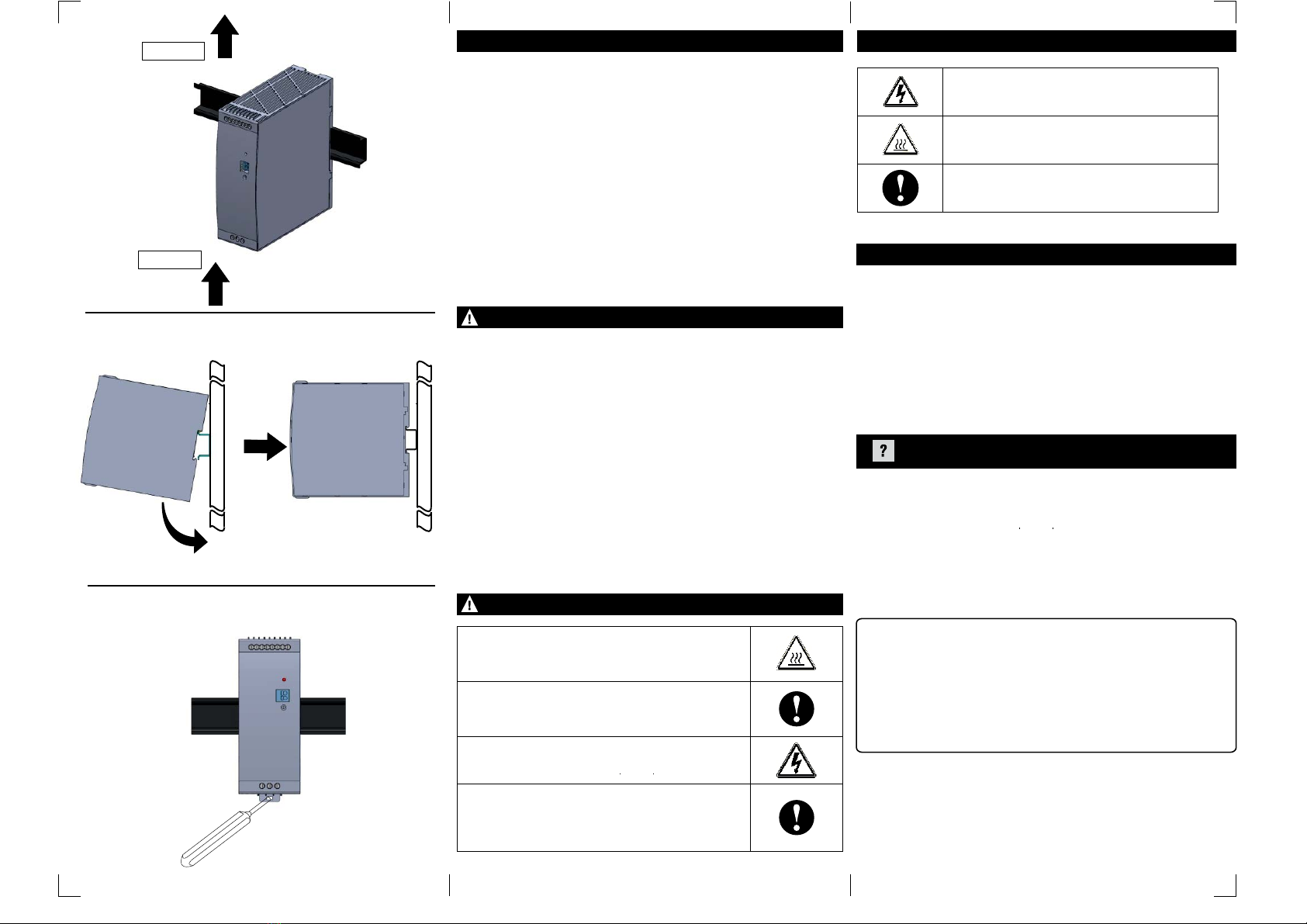
Mounting:(Fig.2)
1. Slightly tilt the unit to engage on the top side of Din Rail mounting.
2. Press it downward until it gets locked in Din Rail.
Removal : (Fig.3)
1. Before removing power supply unit from Din Rail ensure that supply has been
switched off.
2. Unscrew all the wire connections of power supply unit.
3. Insert a screw driver into the mounting clamp slot & pull it down to remove the
power supply from Din Rail.
Doc. name: OP INST RPS480-24-CE OP910-V02(Page 2 of 2)
OUTPUT
INPUT
Fig. 1Fig. 1
Fig. 2
Fig. 3
This power supply is not field serviceable product. In case of failure or
malfunction, send back the power supply to factory.
Please contact service center for repair on the following numbers:
Tel. No. : +91-7498077172;
NO WARRANTY ON UNIT DAMAGED DUE TO WRONG CONNECTION OF
POWER SUPPLY.
(Specifications are subject to change, since development is a
continuous process.)
Factory Address :
EL-27/1, Electronic Zone, TTC Industrial Area,
MIDC, Mahape, Navi Mumbai - 400 710, INDIA.
Tel. No. : +91-22-28476443 / 1882
Fax No. : +91-22-28471733 I Toll free : 1800 227 353
INSTALLATION INSTRUCTIONSINSTALLATION INSTRUCTIONS INSTALLATION INSTRUCTIONSMEANING OF PRODUCT SAFETY SYMBOL
SERVICE
DETAILS
WARNING : Risk of electrical shock, fire, personal injury or death.
Minor burns may occasionally occur.Do not touch the
product while power is being supplied or immediately
after power is turned OFF.
CAUTION
Minor injury due to electric shock may occasionally occur.
Do not touch the terminals while power is being supplied.
If the external breaker or fuse is tripped, the equipment may
have been seriously damaged. Do not turn ON the input
again.
Minor electric shock, fire or product failure may occasionally
occur. Do not allow any pieces of metal or conductors or
any clippings or cuttings resulting from installation work to
enter the product.
ØThis manual is meant for personnel involved in wiring installation
operation & routine maintenance of the equipment.
ØDisconnect power supply of your system before starting any
installation operation or wiring.
ØImproper installation operation or wiring may impair safety & failure
of the unit or electrical shock or damage.
ØConnect the ground completely.A protective earthing terminal
stipulated in safety standards is used. Electric shock or
malfunction may occur if ground is not connected properly.
SAFETY INSTRUCTIONS
Indicates the possibility of electrical shock under
specific conditions
Indicates the possibility of injuries by high temperature
under specific condition
Indicates the instructions of unspecified general action.
3. Make sure mains power supply is off before wiring the power
supply unit. Make sure of correct wiring. Incorrect wiring may
cause electrical shock or damage.
4. Do not touch the power supply during operation or immediately
after turning off because some parts get hot or are at high
voltage which may cause burns or electrical shock.
5. Do not install the power supply where human body may come into
contact while power is supplied to the power supply.
6.
1. Do not use the power supply without proper grounding (Protective
Earth).
2. Do not use in wet locations or in areas where moisture or
condensation can be expected.
Do not repair the power supply at user end . Modification or
repairing of the power supply by users may cause electrical
shocks, damage, & other accidents.
7. If damage or malfunction occurs during operation,
immediately turn off mains power.
Other Selec Power Supply manuals


