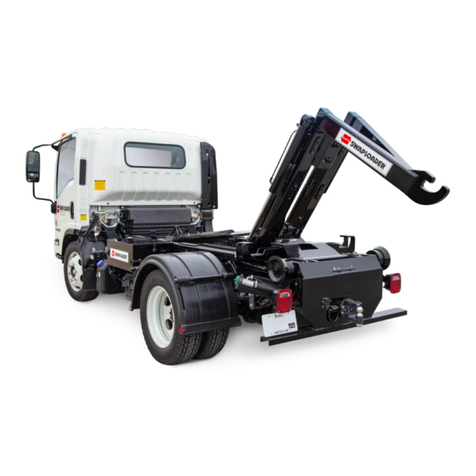
swaploader SL-520X User manual

“Hooked on Quality”
PARTS AND OPERATION MANUAL
HOIST SERIAL NUMBER
MODEL
SL-520X


0.0.TOC.SL-520X
TABLE OF CONTENTS
I. INTRODUCTION
Letter to Customer .....................................................................................................................................1-1
Warranty Statement ..................................................................................................................................1-2
Safety Suggestions ....................................................................................................................................1-3
Decals ........................................................................................................................................................1-5
Serial Number Locations............................................................................................................................1-8
II. INSTALLATION
Initial Inspection .........................................................................................................................................2-1
General Installation Procedure .................................................................................................................. 2-1
Hoist Installation.........................................................................................................................................2-2
Controls Installation – Air Shift...................................................................................................................2-5
Air Control Installation w/ U-Lock or O-Lock (Option)................................................................................2-6
P.T.O. Selection .........................................................................................................................................2-7
Pump Installation........................................................................................................................................2-8
Hydraulic Tank Installation ......................................................................................................................... 2-9
Start Up Procedure ..................................................................................................................................2-10
Subframe Critical Dimensions..................................................................................................................2-11
Stabilizer Installation (Option) ..................................................................................................................2-13
Accessory Installation
Bumper Assembly..............................................................................................................................2-15
Bumper Assembly w/ Extension ........................................................................................................ 2-17
Folding Bumper Assembly................................................................................................................. 2-19
Drop Down Bumper Assembly ..........................................................................................................2-21
Fender Assembly, Tandem Axle .......................................................................................................2-23
Rear Light Bar Assembly...................................................................................................................2-25
Roller & Roller Mount ........................................................................................................................2-29
Toolbox Assembly .............................................................................................................................2-31
III. OPERATION
Loading a Container...................................................................................................................................3-1
Dumping a Container .................................................................................................................................3-2
Placing a Container on the Ground............................................................................................................3-3
Changing Hook Heights (Adj. Jib Option) ..................................................................................................3-4
Rear Roller Spacing Adjustment Instructions ............................................................................................ 3-9
IV. MAINTENANCE
Maintenance Instructions ...........................................................................................................................4-1
Lubrication Diagram ................................................................................................................................... 4-2
Hydraulic Oil Specifications & Interchange Chart ......................................................................................4-3
Hydraulic Filter Element Specification .......................................................................................................4-3
Mast Lock (Pivot Lock) Inspection & Adjustment Instructions ................................................................... 4-4
Jib Lockout Valve Inspection & Adjustment Instructions ........................................................................... 4-5
Pressure Check Instructions ......................................................................................................................4-7
Outer Tube and Jib Wear Pad Replacement Instructions ......................................................................... 4-8

0.0.TOC.SL-520X
V. PARTS
Base Hoist w/ Fixed Jib Assembly .............................................................................................................5-1
Main Frame Sub-Assembly........................................................................................................................5-2
Pivot Joint Sub-Assembly ..........................................................................................................................5-3
Outer Tube Sub-Assembly......................................................................................................................... 5-4
Pivot Lock (Mast Lock) Sub-Assembly ......................................................................................................5-5
Body Lock w/ Shelf Assembly....................................................................................................................5-6
Fixed Jib Sub-Assembly.............................................................................................................................5-7
Hoist Installation Kit.................................................................................................................................... 5-8
Base Cylinder Circuit..................................................................................................................................5-9
Tank Circuit ..............................................................................................................................................5-10
Pump Circuit.............................................................................................................................................5-11
Air Controls, 2-Section .............................................................................................................................5-12
VI. OPTIONS
Adjustable Jib Sub-Assembly.....................................................................................................................6-1
Cylinder Circuit, BL 520X STD – Outside Lock.......................................................................................... 6-2
O-Lock Assembly .......................................................................................................................................6-3
Air Controls, 3-Section ............................................................................................................................... 6-4
Tank Circuit, 3-Section 520X .....................................................................................................................6-6
Stabilizer Assembly.................................................................................................................................... 6-7
Stabilizer Circuit .........................................................................................................................................6-8

SectionI:Introduction
1.0.INT.SL-520X
TO THE CUSTOMER:
Your new SwapLoader Hoist was carefully designed and manufactured to give years of
dependable service. To keep it operating efficiently, read the instructions in this manual
thoroughly. It contains detailed descriptions and instructions for the efficient operation
and maintenance of your SwapLoader. Each section is clearly identified so you can
easily find the information that you need. Read the Table of Contents to learn where
each section is located. All instructions are recommended procedures only.
Throughout this manual you will come across "Dangers," "Warnings," or
"Cautions" which will be carried out in bold type and preceded by the symbol
as indicated to the left. Be certain to carefully read the message that follows to
avoid the possibility of personal injury or machine damage.
Record your SwapLoader Hoist serial number in the appropriate space provided on the
title page. Your SwapLoader dealer needs this information to give prompt, efficient
service when ordering parts. It pays to rely on an authorized SwapLoader Distributor for
your service needs. For the location of the Distributor nearest you, contact SwapLoader.
NOTE: It is SwapLoader's policy to constantly strive to improve SwapLoader products.
The information, specifications, and illustrations in this publication are based on the
information in effect at the time of approval for printing and publishing. SwapLoader
therefore reserves the right to make changes in design and improvements whenever it
is believed the efficiency of the unit will be improved without incurring any obligations to
incorporate such improvements in any unit which has been shipped or is in service. It is
recommended that users contact an authorized SwapLoader Distributor for the latest
revisions.
1-1

SectionI:Introduction
1.0.INT.SL-520X
SWAPLOADER, U.S.A., LTD.
1800 N.E. BROADWAY, DES MOINES, IOWA 50313
LIMITED WARRANTY STATEMENT
Effective September 1, 2009
SwapLoader U.S.A., Ltd., (SwapLoader), warrants to the original purchaser of any new SwapLoader product sold by
an authorized SwapLoader distributor or service center, that such products are free of defects in material and
workmanship. All SwapLoader products with an original factory invoice date of September 1, 2009 or later qualify for
warranty as defined in this Limited Warranty Statement.
Repair or replacement of parts on SwapLoader products are covered under warranty for forty-eight (48)
months from date of Retail Sale by an authorized SwapLoader Distributor or service center, subject to any
applicable federal, state or local taxes, and not to extend beyond sixty (60) months from the original factory
invoice date. SwapLoader will, at its discretion, either repair the defective parts or replace them with
equivalent parts, subject to the conditions below.
Labor charges authorized by the SwapLoader Warranty Department are covered under warranty for a period
of twelve (12) months from the date of Retail Sale by an authorized SwapLoader Distributor or service
center, and not to extend beyond twenty-four (24) months labor from the original factory invoice date.
Warranty Registration Card must be returned within 15 days of Retail Sale of SwapLoader hoist to
SwapLoader, Des Moines, Iowa. If unit has not been registered, then the warranty start date will revert to the
original factory invoice date. Warranty Registration is the ultimate responsibility of the owner and may be
accomplished by the completion and return of the product registration form included in the SwapLoader hoist
manual. If the owner is not sure that product registration is completed, then SwapLoader encourages them
to contact us at 888-767-8000 to confirm.
Defective parts must be reported to SwapLoader within 30 days of discovery on a SwapLoader warranty
claim report form. A Return Goods Authorization (RGA) number must be issued to the claiming party prior
to the return of any defective part to be considered for warranty.
Warranty service must be performed by a distributor or service center authorized by SwapLoader to sell
and/or service SwapLoader products, which will use only new or remanufactured parts or components
furnished by SwapLoader U.S.A., Ltd. SwapLoader will invoice the distributor or authorized service center
for the replacement parts and freight. Upon completion of the repair any defective parts to be returned for
warranty consideration must be returned freight prepaid with a copy of the SwapLoader issued RGA form
and a copy of the completed warranty claim report form. Upon evaluation of the returned parts, once
warranty is approved, credit will be issued to the appropriate account for the approved warranty costs which
may include parts, labor, and/or freight.
The warranty covers only defective material and workmanship. It does not cover depreciation or damage
caused by normal wear and tear, accident, mishap, untrained operators, or improper or unintended use. The
owner has the obligation of performing routine care and maintenance duties as stated in SwapLoader’s
written instructions, recommendations, and specifications. Any damage resulting from owner/ opera-tor
failure to perform such duties shall void the coverage of this warranty. The cost of labor and supplies
associated with routine maintenance will be paid by the owner.
In no event will SwapLoader, the SwapLoader distributor or any company affiliated with SwapLoader be
liable for business interruptions, costs of delay, or for any special, indirect, incidental or consequential costs
or damages. Such costs may include, but are not limited to loss of time, loss of revenue, loss of use, wages,
salaries, commissions, lodging, meals, towing, hydraulic fluid, travel, mileage, or any other incidental costs.
SwapLoader is not responsible for the removal or replacement of accessories (fenders, toolbox, etc.).
Warranty shall not apply if the equipment is operated at capacities in excess of factory recommendations.
Warranty is expressly void if the seal on the main relief control valve has been broken.
SwapLoader will ship the replacement part by the most economical, yet expedient means possible.
Expedited freight delivery will be at the expense of the owner.
Warranty is expressly void if serial number plate or stamping is tampered with.
IT IS EXPRESSLY UNDERSTOOD AND AGREED THAT THERE ARE NO WARRANTIES MADE BY THE MANUFACTURER OR
ITS AGENTS, REPRESENTATIVES OR DISTRIBUTORS, EITHER EXPRESSED, IMPLIED, OR IMPLIED BY LAW, EXCEPT
THOSE EXPRESSLY STATED ABOVE IN THIS STANDARD LIMITED WARRANTY AGAINST DEFECTS IN MATERIAL AND
WORKMANSHIP. THE MANUFACTURER AND ITS AGENTS, REPRESENTATIVES AND DISTRIBUTORS SPECIFICALLY
DISCLAIM ANY IMPLIED WARRANTY OR MERCHANTABILITY OR FITNESS FOR ANY PARTICULAR PURPOSE.
1-2

SectionI:Introduction
1.0.INT.SL-520X
SAFETY SUGGESTIONS
1.
Do not operate or service this equipment until you have
been properly trained and instructed in its use and have
read the operation and service manual.
2.
Do not operate this equipment on uneven ground.
3.
Do not drive with the hoist in the
dump position or with the hook to
the rear.
4.
Do not exceed 1,500 Engine RPM when operating the Power Take Off (P.T.O.).
Never leave the P.T.O. in gear while transporting.
5.
The hoist must be used with containers that properly fit the hook and rear hold-
downs. The container specifications must match the hoist specifications.
6.
Keep the containers and hoist in good working order. DO NOT use if repairs are
needed. Perform periodic inspections and maintenance as required by the
maintenance section of the operator’s manual.
1-3

SectionI:Introduction
1.0.INT.SL-520X
7.
Make sure work area is clear of people and obstacles prior
to dumping or unloading containers. SwapLoader strongly
recommends that a backup alarm be installed on the truck
chassis. The operation of the hook hoist is that the truck is
backed up to the body to pick it up and so there is a
potential pinch point between the body and the hook.
8.
Any container, which is on the hoist, MUST be unloaded
prior to performing any repairs or maintenance to the hoist.
Also, DO NOT allow any person to work on or be under the
hoist in a raised position without first installing adequate
safety blocks to eliminate all possibility of the hoist
accidentally lowering. SwapLoader strongly recommends
that if possible, the container should be dismounted from the
hoist prior to performing any maintenance to the hoist.
9.
It is the responsibility of the owner and/or installer to ensure that any additional safety
devices required by state or local codes are installed on the SwapLoader Hoist
and/or Truck Chassis.
10.
Keep away from overhead power lines. Serious injury or
death can result from contact with electrical lines. Use care
when operating hoist near electrical lines to avoid contact.
11.
Avoid contact with high-pressure fluids. Escaping fluid
under pressure can penetrate the skin causing serious
injury. Avoid hazardous conditions by relieving pressure
before disconnecting hydraulic or other lines. Tighten all
connections before applying pressure. Search for leaks with
a piece of cardboard, while protecting hands and body from
the high-pressure fluids.
12.
It is the responsibility of the owner to provide proper maintenance of the Safety
Decals. Regular inspection and replacing of Safety Decals that have any fading or
damage which would impair their function should be done (See the illustration on the
following page for location of Safety Decals).
1-4

SectionI:Introduction
1.0.INT.SL-520X
ITEM QTY P/N DESCRIPTION
1 2 90P07 OPERATION & SERVICE MANUAL
2 2 90P08 HOIST-BODY SPECIFICATIONS
3 ONE 90P09 HYDRAULIC OIL SPECIFICATIONS
4 ONE 90P10 HYDRAULIC OIL FLAMMABLE
5 2 90P11 HOIST FALLING
6 ONE 90P12 LEVER CONTROL
7 ONE 90P13 SAFETY INSTRUCTIONS
8 2 90P14 SWAPLOADER - JIB
9 ONE 90P18 RELIEF VALVE
10 ONE 90P78 HIGH PRESSURE FLUID
11 2 91P06 LUBRICATION POINTS
12 4 91P47 SL-520X
* 13 2 90P94 ADJ. JIB OPERATION
* Included with the Ad
j
ustable Jib option
1-5

SectionI:Introduction
1.0.INT.SL-520X
The following is a list of all the SwapLoader Safety Decals, and their part numbers. Please use
when reordering replacement decals.
90P07 – OPERATIONS & SERVICE MANUAL
90P08 – HOIST-BODY SPECIFICATIONS
90P09 – HYDRAULIC OIL SPECIFICATIONS
90P10 – HYDRAULIC OIL FLAMMABLE
90P11 – HOIST FALLING
90P12 – LEVER CONTROL
90P13 – SWAPLOADER SAFETY
INSTRUCTIONS
1-6

SectionI:Introduction
1.0.INT.SL-520X
90P14 – SWAPLOADER - JIB
90P18 – RELIEF VALVE
90P78 – HIGH-PRESSURE FLUID
91P06 – LUBRICATION POINTS
91P47 – SL-520
90P94 – ADJUSTABLE JIB OPERATION
1-7

SectionI:Introduction
1.0.INT.SL-520X
Serial Number Locations on a SwapLoader Hoist
Serial Number Tag is located at
the front driver side of the hoist
(gray arrow on first picture).
The Serial Number is also
stamped into the frame of the
hoist on the top of the “inner rail”
shown at the rear of the
hoist
(red arrow on first picture). An
example of a 6-character serial
number is shown in the second
picture.
1-8

SectionII:Installation
2.0.INS.SL-520X
INITIAL INSPECTION
When the hoist is installed and ready for delivery, it is
your responsibility to fill out and submit the Product
Registration Form. Visit
https://www.swaploader.com/warranty-registration/ to
complete this form.
When the SwapLoader hoist is received from the factory,
you should inspect the hoist for damage, which may have
occurred in shipment. If damage has occurred, you
should contact the shipper immediately. Be sure to note
any damage or missing items on bill of Lading.
When you receive your SwapLoader hoist, it is your
responsibility to make sure you have received all the parts
and pieces that were ordered, within 30 days of the
invoice date of the hoist. Lay out all the options, loose
parts and accessories on a table and compare the items
received vs the Packing List and the Loose Parts Box
List(s) shipped with the hoist order.
If you have any problems, shortages, or questions, please
contact SwapLoader U.S.A., Ltd. immediately.
GENERAL INSTALLATION PROCEDURE
The installation of the SwapLoader on a truck chassis will generally follow these steps:
1. Install hoist assembly onto truck chassis.
2. Mount the hydraulic control valve to the hoist and install the hydraulic plumbing from the
control valve to the hydraulic cylinders. Then install the control levers in the cab and
route the control cables to the hydraulic control value assembly.
3. Install the hydraulic tank, hydraulic filter, and hydraulic plumbing between the hydraulic
tank and the control valve assembly.
4. Select and install the P.T.O. on the truck transmission. (Note: This can be done prior to
hoist installation on the truck chassis.)
5. Install the hydraulic pump and the plumbing from the pump to the hydraulic tank and
control valve assembly.
6. Fill the hydraulic tank with oil, bleed the air from the pump suction line, and start up the
unit.
Although SwapLoader attempts to include the mounts and attaching fasteners with each hoist
unit, your installation may require some additional mounts or modifications. If you have
problems with your installation, please contact SwapLoader at 1-888-767-8000, as we may be
aware of another customer who has installed a SwapLoader on a similar truck chassis.
2-1

SectionII:Installation
2.0.INS.SL-520X
HOIST INSTALLATION TO TRUCK CHASSIS
1. Place the SL-520X hoist assembly on the truck chassis. The truck chassis mounting surface
should be flat without any steps or protrusions. If necessary, shim bars need to be added to
ensure a flat surface on which to support hoist. It is advised to clamp the main frame of the
hoist to the truck chassis prior to install of the mount brackets.
The clear frame dimension indicated in Fig. A allows for the overall length of the hoist plus 5
inches for cab clearance and rear light bar mounting. Extra frame length may be needed to
allow for mounting additional accessories (e.g., Cab Guard, Tarper, Light Kit, Stabilizer,
etc.). For example, when mounting a light kit on a truck with a long CT, check that the hoist
and the light kit are positioned far enough back to eliminate any interference between the
fender and the light kit. You should also consider the final weight distribution regarding the
bridge code when positioning the hoist.
NOTE:
THE ABOVE SPECIFICATIONS ARE A MINIMUM REQUIREMENT. IT IS THE RESPONSIBILITY OF THE OWNER/
OPERATOR TO ENSURE THE COMPLETED CHASSIS MEETS OR EXCEEDS ALL FEDERAL, STATE, AND LOCAL
REGULATIONS. ALSO, THE HOIST SHOULD NOT BE USED TO LIFT AND HAUL ANY LOAD THAT EXCEEDS THE LOAD
RATING OF ANY OF THE INDIVIDUAL COMPONENTS OF THE COMPLETED CHASSIS (TIRES, AXLES, SUSPENSION,
ETC.)
2. There are two types of mount brackets used on the Model SL-520X hoist as indicated in Fig.
Band Pg. 5-8. They are the angle brackets (Pt. No. 77H19), and the mid brackets (Pt. No.
76H89). Bolt the mount brackets to the side of the hoist as indicated in Fig. B. Adjust
locations as necessary to miss chassis suspension, brackets, etc. When positioning the
brackets allow for mounting the control valve assembly and the hydraulic tank. You should
consult the truck chassis supplier for any limitations regarding drilling mount holes in the
truck chassis frame rails. Typically, the holes must be at least 2 3/4” from the top of the truck
chassis rails but may vary (reference Fig. C, D & E). Once the locations of the mount
FigureA
2-2

SectionII:Installation
2.0.INS.SL-520X
brackets have been determined, use the mount brackets as a template for marking the
mounting holes in the truck chassis frame rails. Drill the 21/32” diameter holes required and
attach the brackets to the truck chassis with the 5/8” diameter bolts, washers, and locking
hex nuts provided. Torque to 220 ft.lb.
3. Fasten the mount brackets to the hoist main frame as indicated on Fig. C and Fig. D. You
may need to modify the mount brackets or add shim plates to allow for variances in the
width of the truck chassis as well as to allow for top rivets, stepped channels, etc.
Figure
C
FigureB
2-3

SectionII:Installation
2.0.INS.SL-520X
FigureD
Figure
E
2-4

SectionII:Installation
2.0.INS.SL-520X
CONTROLS INSTALLATION - AIR SHIFT
1. Attach the valve mount bracket to the
main frame as indicated on Pg. 5-12
with the fasteners provided.
2. Mount the hydraulic control valve
assembly (Pt. No. 23P21) to the valve
mount bracket as shown on Pg. 5-12
with the fasteners provided.
3. Install the hydraulic adapters and
connect the hydraulic hoses (Pt. Nos.
14P38, 14P39 & 14P40) to the control
valve assembly as indicated on Pg. 5-
10.
4. Determine the best location in the cab
for the control handle assembly (Pt.
No. 20P72). The location should be
such that the controls can be easily
reached while operating the truck. A
control handle console (Pt. No.
51H27) is provided to facilitate the
mounting of the control handles (see
diagram below).
5. Install the air fittings and hose as
shown on Pg. 5-13 (Air Circuit
Plumbing Diagram). An air pressure
protection valve (Pt. No. 20P74) is
provided so you can tap into the
truck's air supply without jeopardizing the integrity of the air system. The air hose is
provided in a bulk length, which you can cut to length as required for running the air lines.
Take care in routing the air lines and avoid hot areas such as exhaust pipes, etc.
2-5

SectionII:Installation
2.0.INS.SL-520X
AIR CONTROL INSTALLATION w/ U-LOCK OR O-LOCK (OPTION)
The Universal Body Lock (U-Lock) can be installed with a standard 3-section valve and
operated from the cab (see Pg. 6-7 for routing). A separate indicator light and harness will be
provided to be installed in the truck cab. This will notify the operator when the U-Lock has been
engaged or disengaged.
1. Review all directions and diagrams provided before starting installation.
2. Mount valve to the hoist’s Main Frame and attach all hoses, hose clamp
assemblies and fittings as shown on Pg. 6-8.
3. Mount Indicator Light Box in the truck cab where it will
be clearly visible to the operator.
4. Route Indicator Light and Harness (Pt. No.
40P60) from the truck cab to the U-Lock/O-
Lock cylinder.
5. Hardwire or plug in provided 12V
adapter for indicator
light.
NOTE:
AS A SAFETY MEASURE, THE JIB CYLINDER IS
DISENGAGED WHENEVER THE U-LOCK/O-LOCK
IS ENGAGED.
2-6

SectionII:Installation
2.0.INS.SL-520X
P.T.O. SELECTION
The next step is to select and install a direct drive type P.T.O. to the transmission. Please
contact your local truck equipment representative for the correct unit sized on the following
criteria which is based on the SwapLoader provided pump:
P.T.O. Torque Rating: 270 ft.-lbs. (See Note 1)
Power at 1500 RPM: 62 H.P. (See Note 1)
Mount Flange (Direct Mount): SAE B-B 4 Bolt
Hydraulic Pump Spline Shaft
Specifications:
1-15T 16/32 D.P.
Hydraulic Pump Rotation: Bi-Rotational. Factory set @ RH rotation.
Rotation can be reversed by installing inlet fitting on
the required side depending on PTO rotation. The
pump will set itself accordingly.
HOW TO IDENTIFY WHAT PUMP IS NEEDED
The SwapLoader factory supplied pump is a bent axis piston pump designed to be installed in
environments with little space available.
NOTE:
CONSULT THE PTO SUPPLIER WHENEVER UNCERTAIN ABOUT THE CORRECT PUMP ROTATION FOR A
PARTICULAR APPLICATION.
The table lists the SwapLoader part number of the
pump for the SL-520X hoist model:
NOTE:
THE SWAPLOADER PUMP COMES EQUIPPED WITH A PROTECTIVE TUBE WHICH AVOIDS ENTRY OF CONTAMINANTS
AND ALLOWS FOR AIR VENTILATION.
RECOMMENDATIONS FOR ATTACHING THE PROTECTIVE
TUBE:
MAKE SIPHON WITH THE TUBE SO AS TO AVOID ANY
INTRODUCTION OF DIRT FROM ROAD, AND WATER
OR DAMP FROM HIGH PRESSURE WASHING OF
VEHICLE.
PUT THE END OF THE TUBE DOWNWARDS, OR IN A
PLACE SHELTERED FROM ANY PROJECTIONS.
FIX THE TUBE IN PLACE USING A COLLAR/CLIP
AVOID ATTACHING THE TUBE TO ANY PARTS WHICH
MAY MOVE, THIS COULD LEADTOIT BEING DAMAGED.
AVOID ANY PINCHING OR FOLDS IN THE TUBE WHEN
FIXING IT IN PLACE.
MAKE SURE THE END OF THE TUBE IS NOT BLOCKED.
P.T.O. NOTES:
1. P.T.O. TORQUE AND POWER REQUIREMENTS ARE BASED ON THE UNIT OPERATING AT MAIN RELIEF
PRESSURE. NORMAL OPERATING PRESSURE WILL BE LESS.
2. P.T.O. OUTPUT ROTATION WILL NEED TO BE R.H. (CLOCKWISE) AS VIEWED LOOKING AT OUTPUT FLANGE OF
P.T.O. FOR A L.H. PUMP.
3. DO NOT OPERATE PUMP AT SPEEDS OVER 1500 R.P.M.
4. ALWAYS DISENGAGE THE P.T.O. AFTER EACH OPERATING CYCLE.
MODEL BI-ROTATIONAL PUMP
SL-520X 23P20
2-7

SectionII:Installation
2.0.INS.SL-520X
HOW TO IDENTIFY PUMP ROTATION
To better understand the effects of pump rotation we must consider the path that oil takes
through the pump. Oil enters the pump through the inlet (suction) port, travels around the
outside of the gears, and is forced out through the outlet (exhaust) port. Oil enters and exits the
pump in the direction of its rotation.
Determine pump rotation by positioning the pump belly side down (see illustration above).
Looking at the rear of the pump if the suction (largest) port is to the left side, then the pump is a
CCW or left-hand rotation. If the suction (largest) port is on the right side, then the pump is CW
or right-hand rotation.
PUMP INSTALLATION
1. Install the hydraulic pump to the P.T.O. (Bolts are not provided).
2. Install the hydraulic fittings into ports on the hydraulic pump as
shown on Pg. 5-11.
3. Connect the suction hose assembly to the hydraulic tank (1-1/2"
I.D. hose) and route to the hydraulic pump in as short and straight
line as possible. Be sure to route the hose clear of exhaust
components and of the drive shaft. Extra hose is provided so the
hose can be shortened to an appropriate length. Install the hose
on the hose barb fittings at the tank and at the pump and secure
with the hose clamps provided.
NOTE: Prior to startup, this hose must be filled with oil.
4. The pressure hose from the hydraulic pump to the control valve
assembly is not supplied with the hoist as it must be made to the
proper length. This hose must be purchased from a local hydraulic
hose assembly supplier per the following specification:
a. Hose ID: 3/4 inch
b. Working Pressure: 5000 PSI
c. Hose Fitting Threads: SAE O-Ring Face Seal 1 3/16-12
2-8
Table of contents
Other swaploader Lifting System manuals
Popular Lifting System manuals by other brands

Show Tec
Show Tec MAT-350 Line Array Tower V2 manual

Dino lift
Dino lift DINO 105TL operating instructions

RIGHT ANGLE
RIGHT ANGLE 4 HV Series Assembly instructions

Tommy Gate
Tommy Gate V2 Series Owner's and operator's manual

BraunAbility
BraunAbility Vista 2 owner's manual

Tadano
Tadano TM-2000-1 Service manual