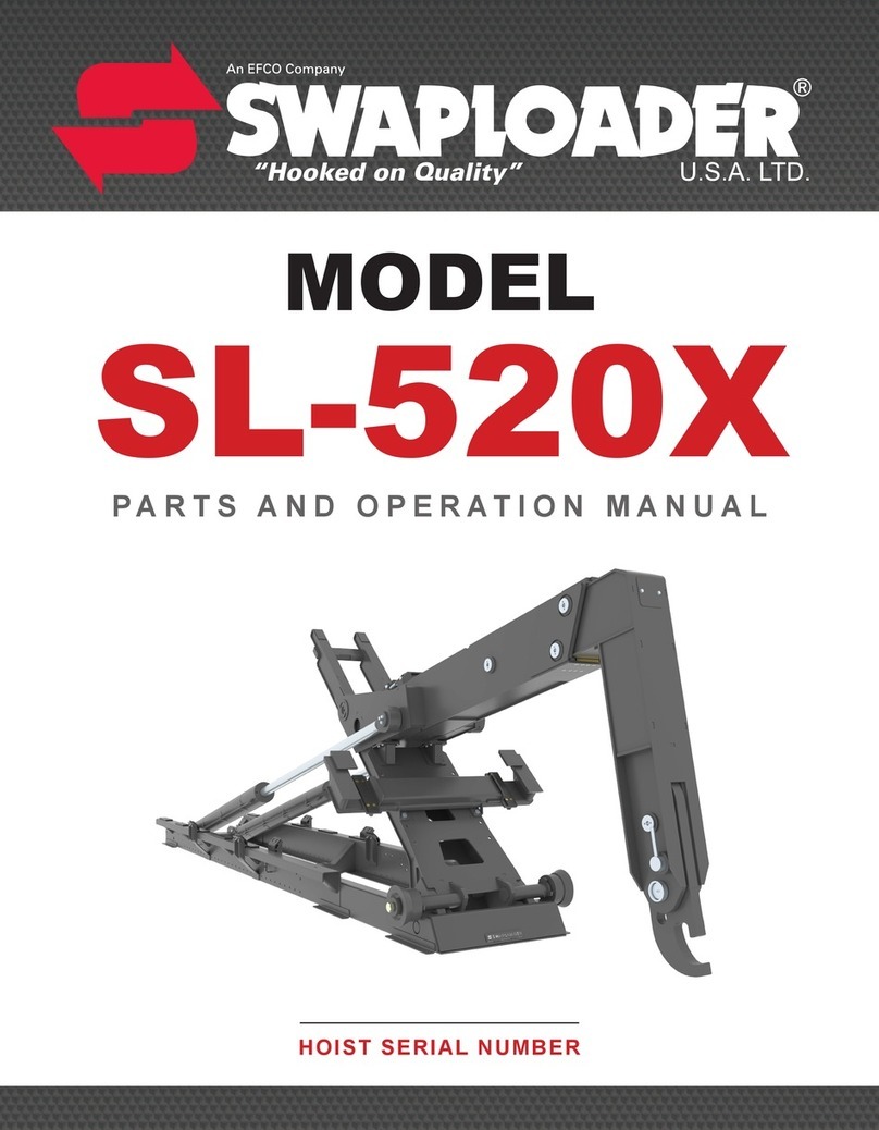
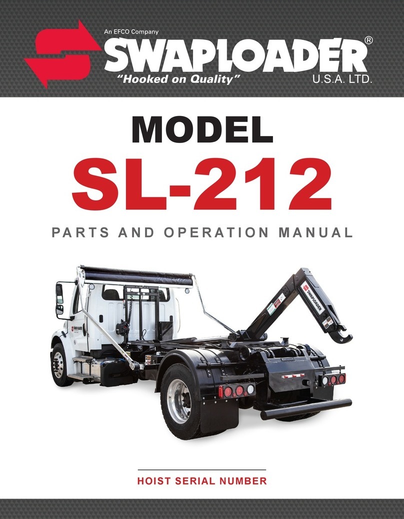
swaploader SL-75 User manual

“Hooked on Quality”
PARTS AND OPERATION MANUAL
HOIST SERIAL NUMBER
MODEL
SL-75


0.0.TOC.SL-75
TABLE OF CONTENTS
I. INTRODUCTION
Letter to Customer................................................................................................................................ 1-1
Warranty Statement ............................................................................................................................. 1-2
Safety Suggestions............................................................................................................................... 1-3
Decals.................................................................................................................................................. 1-5
Serial Number Locations....................................................................................................................... 1-8
II. INSTALLATION
Initial Inspection.................................................................................................................................... 2-1
General Installation Procedure.............................................................................................................. 2-1
Hoist Installation ................................................................................................................................... 2-2
Spacer Kit Installation........................................................................................................................... 2-4
Power Pack Installation ........................................................................................................................ 2-4
Connecting Power Pack Hydraulic Hoses...................................................................................... 2-6
Power Pack Electrical Wiring ........................................................................................................ 2-8
EHV Installation.................................................................................................................................. 2-10
EHV Manual Over-Ride Instructions.................................................................................................... 2-12
P.T.O./Pump Selection ....................................................................................................................... 2-13
Hydraulic Tank Installation.................................................................................................................. 2-13
Start Up Procedure............................................................................................................................. 2-14
Subframe Dimensions ........................................................................................................................ 2-15
Accessory Installation
Roller & Roller Mount.................................................................................................................. 2-17
Toolbox Assembly ...................................................................................................................... 2-19
III. OPERATION
Loading a Container ............................................................................................................................. 3-1
Dumping a Container............................................................................................................................ 3-2
Placing a Container on the Ground....................................................................................................... 3-3
IV. MAINTENANCE
Maintenance Instructions..................................................................................................................... .4-1
Lubrication Diagram ............................................................................................................................. 4-2
Hydraulic Oil Specifications .................................................................................................................. 4-3
Hydraulic Filter Specifications............................................................................................................... 4-3
Mast Lock (Pivot Lock) Inspection & Adjustment Instructions ................................................................ 4-4
Jib Proximity Sensor Inspection & Adjustment Instructions.................................................................... 4-5
Pressure Check Instructions (Power Pack) ........................................................................................... 4-6
Pressure Check Instructions (EHV)....................................................................................................... 4-8
V. PARTS
Base Hoist Assembly............................................................................................................................ 5-1
Main Frame Assembly.......................................................................................................................... 5-2
Pivot Joint Assembly............................................................................................................................. 5-3
Outer Tube Assembly........................................................................................................................... 5-4
Safety Latch Assembly ......................................................................................................................... 5-5
Body Lock Assembly ............................................................................................................................ 5-6
Hoist Installation Kit.............................................................................................................................. 5-7
Base Cylinder Circuit ............................................................................................................................ 5-8

0.0.TOC.SL
-
75
V. OPTIONS
Spacer Kit............................................................................................................................................. 6-1
Tank Circuit (EHV)................................................................................................................................ 6-2
Hose Circuit (EHV) ............................................................................................................................... 6-3

Section I: Introduction
1.0.INT.SL-75
TO THE CUSTOMER:
Your new SwapLoader Hoist was carefully designed and manufactured to give years of
dependable service. To keep it operating efficiently, read the instructions in this manual
thoroughly. It contains detailed descriptions and instructions for the efficient operation
and maintenance of your SwapLoader. Each section is clearly identified so you can
easily find the information that you need. Read the Table of Contents to learn where
each section is located. All instructions are recommended procedures only.
Throughout this manual you will come across "Dangers," "Warnings," or
"Cautions" which will be carried out in bold type and preceded by the symbol
as indicated to the left. Be certain to carefully read the message that follows to
avoid the possibility of personal injury or machine damage.
Record your SwapLoader Hoist serial number in the appropriate space provided on the
title page. Your SwapLoader dealer needs this information to give prompt, efficient
service when ordering parts. It pays to rely on an authorized SwapLoader Distributor for
your service needs. For the location of the Distributor nearest you, contact SwapLoader.
NOTE: It is SwapLoader's policy to constantly strive to improve SwapLoader products.
The information, specifications, and illustrations in this publication are based on the
information in effect at the time of approval for printing and publishing. SwapLoader
therefore reserves the right to make changes in design and improvements whenever it
is believed the efficiency of the unit will be improved without incurring any obligations to
incorporate such improvements in any unit which has been shipped or is in service. It is
recommended that users contact an authorized SwapLoader Distributor for the latest
revisions.
1-1

Section I: Introduction
1.0.INT.SL-75
SWAPLOADER, U.S.A., LTD.
1800 N.E. BROADWAY, DES MOINES, IOWA 50313
LIMITED WARRANTY STATEMENT
Effective September 1, 2009
SwapLoader U.S.A., Ltd., (SwapLoader), warrants to the original purchaser of any new SwapLoader product sold by
an authorized SwapLoader distributor or service center, that such products are free of defects in material and
workmanship. All SwapLoader products with an original factory invoice date of September 1, 2009 or later qualify for
warranty as defined in this Limited Warranty Statement.
Repair or replacement of parts on SwapLoader products are covered under warranty for forty-eight (48)
months from date of Retail Sale by an authorized SwapLoader Distributor or service center, subject to any
applicable federal, state or local taxes, and not to extend beyond sixty (60) months from the original factory
invoice date. SwapLoader will, at its discretion, either repair the defective parts or replace them with
equivalent parts, subject to the conditions below.
Labor charges authorized by the SwapLoader Warranty Department are covered under warranty for a period
of twelve (12) months from the date of Retail Sale by an authorized SwapLoader Distributor or service
center, and not to extend beyond twenty-four (24) months labor from the original factory invoice date.
Warranty Registration Card must be returned within 15 days of Retail Sale of SwapLoader hoist to
SwapLoader, Des Moines, Iowa. If unit has not been registered, then the warranty start date will revert to the
original factory invoice date. Warranty Registration is the ultimate responsibility of the owner and may be
accomplished by the completion and return of the product registration form included in the SwapLoader hoist
manual. If the owner is not sure that product registration is completed, then SwapLoader encourages them
to contact us at 888-767-8000 to confirm.
Defective parts must be reported to SwapLoader within 30 days of discovery on a SwapLoader warranty
claim report form. A Return Goods Authorization (RGA) number must be issued to the claiming party prior
to the return of any defective part to be considered for warranty.
Warranty service must be performed by a distributor or service center authorized by SwapLoader to sell
and/or service SwapLoader products, which will use only new or remanufactured parts or components
furnished by SwapLoader U.S.A., Ltd. SwapLoader will invoice the distributor or authorized service center
for the replacement parts and freight. Upon completion of the repair any defective parts to be returned for
warranty consideration must be returned freight prepaid with a copy of the SwapLoader issued RGA form
and a copy of the completed warranty claim report form. Upon evaluation of the returned parts, once
warranty is approved, credit will be issued to the appropriate account for the approved warranty costs which
may include parts, labor, and/or freight.
The warranty covers only defective material and workmanship. It does not cover depreciation or damage
caused by normal wear and tear, accident, mishap, untrained operators, or improper or unintended use. The
owner has the obligation of performing routine care and maintenance duties as stated in SwapLoader’s
written instructions, recommendations, and specifications. Any damage resulting from owner/ opera-tor
failure to perform such duties shall void the coverage of this warranty. The cost of labor and supplies
associated with routine maintenance will be paid by the owner.
In no event will SwapLoader, the SwapLoader distributor or any company affiliated with SwapLoader be
liable for business interruptions, costs of delay, or for any special, indirect, incidental or consequential costs
or damages. Such costs may include, but are not limited to loss of time, loss of revenue, loss of use, wages,
salaries, commissions, lodging, meals, towing, hydraulic fluid, travel, mileage, or any other incidental costs.
SwapLoader is not responsible for the removal or replacement of accessories (fenders, toolbox, etc.).
Warranty shall not apply if the equipment is operated at capacities in excess of factory recommendations.
Warranty is expressly void if the seal on the main relief control valve has been broken.
SwapLoader will ship the replacement part by the most economical, yet expedient means possible.
Expedited freight delivery will be at the expense of the owner.
Warranty is expressly void if serial number plate or stamping is tampered with.
IT IS EXPRESSLY UNDERSTOOD AND AGREED THAT THERE ARE NO WARRANTIES MADE BY THE MANUFACTURER OR
ITS AGENTS, REPRESENTATIVES OR DISTRIBUTORS, EITHER EXPRESSED, IMPLIED, OR IMPLIED BY LAW, EXCEPT
THOSE EXPRESSLY STATED ABOVE IN THIS STANDARD LIMITED WARRANTY AGAINST DEFECTS IN MATERIAL AND
WORKMANSHIP. THE MANUFACTURER AND ITS AGENTS, REPRESENTATIVES AND DISTRIBUTORS SPECIFICALLY
DISCLAIM ANY IMPLIED WARRANTY OR MERCHANTABILITY OR FITNESS FOR ANY PARTICULAR PURPOSE.
1-2

Section I: Introduction
1.0.INT.SL-75
SAFETY SUGGESTIONS
1.
Do not operate or service this equipment until you have
been properly trained and instructed in its use and have
read the operation and service manual.
2.
Do not operate this equipment on uneven ground.
3.
Do not drive with the hoist in the
dump position or with the hook to
the rear.
4.
Do not exceed 1,500 Engine RPM when operating the Power Take Off (P.T.O.).
Never leave the P.T.O. in gear while transporting.
5.
The hoist must be used with containers that properly fit the hook and rear hold-
downs. The container specifications must match the hoist specifications.
6.
Keep the containers and hoist in good working order.
DO NOT
use if repairs are
needed. Perform periodic inspections and maintenance as required by the
maintenance section of the operator’s manual.
1-3

Section I: Introduction
1.0.INT.SL-75
7.
Make sure work area is clear of people and obstacles prior
to dumping or unloading containers. SwapLoader strongly
recommends that a backup alarm be installed on the truck
chassis. The operation of the hook hoist is that the truck is
backed up to the body to pick it up and so there is a
potential pinch point between the body and the hook.
8.
Any container, which is on the hoist,
MUST
be unloaded
prior to performing any repairs or maintenance to the hoist.
Also, DO NOT allow any person to work on or be under the
hoist in a raised position without first installing adequate
safety blocks to eliminate all possibility of the hoist
accidentally lowering.
9.
It is the responsibility of the owner and/or installer to insure that any additional safety
devices required by state or local codes are installed on the SwapLoader Hoist
and/or Truck Chassis.
10.
Keep away from overhead power lines. Serious injury or
death can result from contact with electrical lines. Use care
when operating hoist near electrical lines to avoid contact.
11.
Avoid contact with high-pressure fluids. Escaping fluid
under pressure can penetrate the skin causing serious
injury. Avoid hazardous conditions by relieving pressure
before disconnecting hydraulic or other lines. Tighten all
connections before applying pressure. Search for leaks with
a piece of cardboard, while protecting hands and body from
the high-pressure fluids.
12.
It is the responsibility of the owner to provide proper maintenance of the Safety
Decals. Regular inspection and replacing of Safety Decals that have any fading or
damage which would impair their function should be done (See the illustration on the
following page for location of Safety Decals).
1-4

Section I: Introduction
1.0.INT.SL-75
ITEM QTY P/N DESCRIPTION
1
2 90P07 OPERATION & SERVICE MANUAL
2
2 90P08 HOIST-BODY SPECIFICATIONS
3
ONE 90P09 HYDRAULIC OIL SPECIFICATIONS
4
ONE 90P10 HYDRAULIC OIL FLAMMABLE
5
2 90P11 HOIST FALLING
6
ONE 90P13 SAFETY INSTRUCTIONS
7
2 90P14 SWAPLOADER - JIB
8
ONE 90P18 RELIEF VALVE
9
ONE 90P78 HIGH-PRESSURE FLUID
10
2 91P06 LUBRICATION POINTS
11
4 91P24 SL-75
1-5

Section I: Introduction
1.0.INT.SL-75
The following is a list of all the SwapLoader Safety Decals, and their part numbers. Please use
when reordering replacement decals.
90P07 – OPERATIONS & SERVICE MANUAL
90P08 – HOIST-BODY SPECIFICATIONS
90P09 – HYDRAULIC OIL SPECIFICATIONS
90P10 – HYDRAULIC OIL FLAMMABLE
90P11 – HOIST FALLING
90P13 – SWAPLOADER SAFETY
INSTRUCTIONS
90P14 – SWAPLOADER - JIB
1-6

Section I: Introduction
1.0.INT.SL-75
90P18 – RELIEF VALVE
90P78 – HIGH-PRESSURE FLUID
91P06 – LUBRICATION POINTS
91P24 – SL-75
1-7

Section I: Introduction
1.0.INT.SL-75
SERIAL NUMBER LOCATIONS ON A SWAPLOADER HOIST
Serial Number Tag is located at
the front driver side of the hoist
(gray arrow on first picture).
The Serial Number is also
stamped into the frame of the
hoist on the top of the “inner rail”
shown at the rear of the
hoist
(red arrow on first picture). An
example of a 6-character serial
number is shown in the second
picture.
1-8

Section II: Installation
2.0.INS.SL-75
INITIAL INSPECTION
When the hoist is installed and ready for delivery, it is
your responsibility to fill out and submit the Product
Registration Form. Visit
https://www.swaploader.com/warranty-registration/ to
complete this form.
When the SwapLoader hoist is received from the factory,
you should inspect the hoist for damage, which may have
occurred in shipment. If damage has occurred, you
should contact the shipper immediately. Be sure to note
any damage or missing items on bill of Lading.
When you receive your SwapLoader hoist, it is your
responsibility to make sure you have received all the parts
and pieces that were ordered, within 30 days of the
invoice date of the hoist. Lay out all the options, loose
parts and accessories on a table and compare the items
received vs the Packing List and the Loose Parts Box
List(s) shipped with the hoist order.
If you have any problems, shortages, or questions, please
contact SwapLoader U.S.A., Ltd. immediately.
GENERAL INSTALLATION PROCEDURE
The installation of a SL-75 on a truck chassis will generally follow these steps:
1. Install hoist assembly onto truck chassis.
2. Install a PowerPack or EHV system to the hoist and install the hydraulic plumbing from
the control valve to the hydraulic cylinders. Then install the control switchbox in the cab
and route the harnesses to the PowerPack or EHV and truck battery.
If utilizing an EHV complete the following additional steps:
3. Select and install the P.T.O. on the truck transmission. (Note: This can be done prior to
hoist installation on the truck chassis.)
4. Install the hydraulic pump and the plumbing from the pump to the hydraulic tank and
control valve assembly.
5. Fill the hydraulic tank with oil, bleed the air from the pump suction line, and start up the
unit.
Although SwapLoader attempts to include the mounts and attaching fasteners with each hoist
unit, your particular installation may require some additional mounts or modifications. If you
have problems with your installation, please contact SwapLoader at 1-888-767-8000, as we
may be aware of another customer who has installed a SwapLoader on a similar truck chassis.
2-1

Section II: Installation
2.0.INS.SL-75
Figure
B
HOIST INSTALLATION TO TRUCK CHASSIS
1. Place the SL-75 hoist assembly on the truck chassis. The truck chassis mounting surface
should be flat without any steps or protrusions. If necessary shim bars need to be added to
ensure a flat surface on which to support hoist. It is advised to clamp the main frame of the
hoist to the truck chassis prior to install of the mount brackets.
The clear frame dimension indicated in Fig. A allows for the overall length of the hoist plus 5
inches for cab clearance and rear light bar mounting. Extra frame length may be needed to
allow for mounting additional accessories (e.g. Cab Guard, Tarper, Light Kit, Stabilizer, etc.).
For example, when mounting a light kit on a truck with a long CA, check that the hoist and
the light kit are positioned far enough back to eliminate any interference between the fender
and the light kit. You should also consider the final weight distribution with regard to the
bridge codes and axle GVWR when positioning the hoist.
NOTE:
THE ABOVE SPECIFICATIONS ARE A MINIMUM REQUIREMENT. IT IS THE RESPONSIBILITY OF THE OWNER/
OPERATOR TO ENSURE THE COMPLETED CHASSIS MEETS OR EXCEEDS ALL FEDERAL, STATE, AND LOCAL
REGULATIONS. ALSO, THE HOIST SHOULD NOT BE USED TO LIFT AND HAUL ANY LOAD THAT EXCEEDS THE LOAD
RATING OF ANY OF THE INDIVIDUAL COMPONENTS OF THE COMPLETED CHASSIS (TIRES, AXLES, SUSPENSION,
ETC.)
2. There are three types of mount brackets used on the Model SL-75 hoist as indicated in Fig.
Band Pg. 5-7. They are the front brackets (Pt. No. 25H91), the mid brackets (Pt. No.
25H89) and the rear brackets (Pt. No. 26H74). Locate the mount brackets on the side of the
Figure
A
2-2

Section II: Installation
2.0.INS.SL-75
hoist as indicated in Fig. B. These dimensions are flexible because of possible interference
with chassis components. Also allow for mounting the Power Pack. You should consult the
truck chassis supplier for any limitations regarding drilling mount holes in the truck chassis
frame rails. Typically, the holes must be at least 2 3/4” from the top of the truck chassis rails
(reference Fig. C, Fig. D & Fig. E). Mid brackets will have more flexibility due to the
additional row of holes in the Main Frame and allows for drilling into the truck chassis frame
rails at 2 3/4”, 3 3/4” or 4 3/4” (bolts are only required on two of the four lower mount
bracket holes). Once the locations of the mount brackets have been determined, use the
mount brackets as a template for marking the mounting holes in the truck chassis frame
rails. Drill the 17/32” diameter holes required and attach the brackets to the truck chassis
with the 1/2” diameter bolts,
washers, and locking hex
nuts provided. Torque to
110 ft.lb.
3. Bolt the mount brackets to
the hoist main frame as
indicated on Fig. C, D and E.
You may need to modify the
mount brackets or add shim
plates to allow for variances
in the width of the truck
chassis as well as to allow
for top rivets, stepped
channels, etc.
Figure C
Figure D
Figure E
Figure
C
2-3

Section II: Installation
2.0.INS.SL-75
SPACER KIT INSTALLATION
The SL-75 has made available an alternative option when installing to the truck chassis. The
Spacer Kit (Pt. No. 13H49) allows for the hoist to be raised to account for any interferences from
components of the truck that are above the chassis. The main frame of the hoist will have pre-
drilled holes into
the bottom flange
that will sit on top
of the spacer
provided in the
spacer kit. Be sure
to drill Ø1/4” holes
into the spacers to
drive the spring
pins into.
POWER PACK INSTALLATION
Introduction to the Power Pack: The SwapLoader Power Pack provides on demand hydraulic
power from a self-contained power unit which consists of a gear pump, 24V electric motor,
directional valve, and reservoir. In order to provide 24V to the motor, an additional 12V AGM 27
or AGM 31 auxiliary battery is required. The auxiliary battery is connected first to a series
parallel switch and then subsequently to the truck batteries through the series parallel switch.
This configuration allows for the auxiliary battery to charge in parallel with the truck batteries at
12V while the Power Pack is not engaged. When the in-cab control switch activates the power
unit, this simultaneously triggers the series parallel switch and places the auxiliary battery in
series with the truck battery thus providing 24V to the electric motor.
Also integrated into the hydraulic system is a ferrous proximity sensor, which detects only
metal. In the case of the SL-75, the proximity sensor will sense the outer tube while it is in a flat
position. When the outer tube is not flat, the sensor will not allow a signal to be sent to the jib
section of the control valve, which effectively disables the jib function of the hoist
Figure F
2-4

Section II: Installation
2.0.INS.SL-75
1. Review all directions and diagrams
provided before starting the SwapLoader
Power Pack installation.
2. Mount Right and Left Bracket to hoist
main frame. Holes are predrilled on the
main frame of the hoist. Measure 21”
between the two holes as shown in Fig.
G. If a 21” dimension is not possible due
to truck constraints, the bracket can be
brought closer together. In this case, use
a dimension of 15”. Use 1/2” bolts, washers and nylon nuts to secure the brackets to the
main frame. Depending on truck frame width, it may be necessary to add shims (not
included) to either the main frame or truck frame in order to mount brackets flush.
3. Drill 17/32” diameter holes into the truck frame. The distance between
the holes will be dependent on whether the standard 21” spacing was
used between the two brackets. Use 1/2” bolts, washers and nylon
nuts.
22P72 – Power Pack
ITEM QTY DESCRIPTION
1 1 Cover, Power Pack
2 1 Power Pack Support Bracket, Right
3 1 Power Pack Support Bracket, Left
4 8 HHCS 3/8-16 x 1 Gr8
5 8 Washer, Flat 3/8 Dia
6 8 Nut, Hex 3/8-16 Gr8
7 8 HHCS 1/2-13 x 1-1/2 Pl Gr8
8 8 Washer, Flat 1/2 Pl
9 8 Nut, Nylon 1/2-13 Gr8
Figure G
4.
Bolt The SWL Power Pack
to the brackets. Use 3/8”
bolts, washers, and hex
nuts
2-5

Section II: Installation
2.0.INS.SL-75
CONNECTING POWER PACK HYDRAULIC HOSES
5. Hook up hydraulic hoses to the lift
cylinders as shown in Fig. H. Use
item 1, 2 & 3 to secure hoses to the
main frame of the hoist.
6. See Fig. I for connecting the hyd
lines to the jib. Use items 1, 2 & 3 to
fasten hyd hoses to the main frame
of the hoist. See Pg. 4-5 in your
manual for a detailed view of proximity sensor
adjustment.
Power Pack Hose Circuit
ITEM
PART
# QTY DESCRIPTION
1 10P63 2 HHCS 5/16 x 1-3/4
2 10P64 2 Cover Plate, Clamp 1/2”
3 10P65 2 Clamp Assy, Twin 7/8”
4 13P69 1 Proximity Sensor
5 13P70 2 Hose Assy 65 08-08FJ/08FJ
6 13P71 2 Hose Assy 70 08-08FJ/08FJ90
Figure H
Figure I
2-6

Section II: Installation
2.0.INS.SL-75
Power Pack- SERVICE PARTS SL-
75
ITEM
PART
# QTY DESCRIPTION
1 11P24 4 Adp Hyd 08MJ/08MJ 90
2 13P68 2 Hose Assy 17.5 08-08FJ/08FJ
3 13P69 2 Hose Assy 28 08-08FJ/08FJ
4 22P68 1 Hyd Power Unit, 24V
5 22P79 1 Access Gasket, Power Pack
6 22P80 1 Access Plate, Power Pack
7 22P81 2 Adhesive Gasket, 5/8W x 3/8H
8 40P48 1 12V/24V Series Parallel Switch
9 91P28 4 Draw Latch w/ Strike Plate
2-7

Section II: Installation
2.0.INS.SL-75
POWER PACK ELECTRICAL WIRING
7. Locate the nearest truck battery to the Power Pack, this will be the battery the power pack
will tie in to. Install the provided
350A fuse to the positive terminal of
this battery.
Hyd Hose install – Electrical Service Parts SL-75
ITEM
PART
# QTY DESCRIPTION
1 13P61 1 Proximity Sensor w/ Harness
2 40P47 2 Fuse Kit, 350A
3 40P49 1 Cable, Red 1/0 Ga. x 13’
4 40P50 1 Cable, Black 1/0 Ga. x 13’
5 40P51 2 Wire, Green 16 Ga. x 10”
6 40P52 1 Wire, Black 16 Ga. x 8”
7 40P53 1 Wire, Black 16 Ga. x 4”
8 40P54 1 Cable, Red 1/0 Ga. x 12”
9 40P55 1 Cable, Black 1/0 Ga. x 12”
10 40P56 1 Cable, Black 1/0 Ga. x 2’
11 40P57 1 Cable, Red 1/0 Ga. x 1.5’
12 40P58 2 Diode Assembly, 6A
13 40P59 1 Harness, Valve Solenoids
BATTERY
SELECTION
SwapLoader recommends utilizing 700 cca
minimum 12V AGM27 or AGM31 auxiliary battery.
Vented or refillable are not acceptable.
2-8
Table of contents
Other swaploader Lifting System manuals
Popular Lifting System manuals by other brands

Nussbaum
Nussbaum UNI-LIFT 5000 CLT PLUS Operating Instruction and Documentation

BERG
BERG BENOMIC STAR 300 Technical handbook

REID LIFTING
REID LIFTING PORTABASE PBHB00001 Assembly & Operation guide

Kesseböhmer
Kesseböhmer DR!VE Mini Assembly instructions

Nußbaum Hebetechnik
Nußbaum Hebetechnik 4.40H Instructions and Documentation

Active Mobility
Active Mobility NEOS 150 Folding user manual