SWH Solar Racking User manual

SWH Solar Racking
Installation Guide
9628 Valley Blvd. Rosemead, CA 91770 | Phone 626-579-3288 | inf[email protected]
Version 12.10.v2

Table of Contents
i. Installer’s Responsibilities ............................................................................................
Part I. Procedure to Determine the Design Wind Load...............................
[1.1] Using the Low Rise Buildings (Simplified) Method - ASCE 7-10...............................
[1.2] Procedure to Calculate Total Design Wind Load per ASCE 7-10.............................
Part II. Procedure to Select Rail Span and Foot Spacing .......................
[2.1] Using Standard Beam Calculations, Structural Engineering Methodology ............
Part III. Installing SWH Solar Racking System .....................................................
[3.1] SWH Solar Racking Components ......................................................................................
[3.2] Installing SWH with Top Mounting Clamps ....................................................................
[3.2.1] Planning Your SWH Racking Installations ....................................................................
[3.2.2] Laying Out L-Brackets ......................................................................................................
[3.2.3] Laying Out Standoffs ........................................................................................................
[3.2.4] Installing Tile Struts ..........................................................................................................
[3.2.5] Installing Flashed L Feet .................................................................................................
{3.2.6] Installing Roof Bar.............................................................................................................
[3.2.7] Installing Roof Hook ........................................................................................................
[3.2.8] Installing SWH Rails and Splices....................................................................................
[3.2.9] Installing the Modules .....................................................................................................
[3.3] Grounding Path Diagram and Components....................................................................
[3.4] Installer Warning and Notice .............................................................................................
Warranty Sheet ..............................................................................................................................
3
4
4
5
20
21
24
24
26
27
28
29
30
31
32
33
34
35
37
38
40
2

i. Installer’s Responsibilities
The installer is solely responsible for:
• Complying with all applicable local or national building
codes, including any that may supersede this manual;
• Ensuring that SWH and other products are appropriate for
the particular installation and the installation environment;
• Ensuring that the roof, its rafters, connections, and other
structural support members can support the array under all
code level loading conditions (this total building assembly is
referred to as the building structure);
• Using only SWH parts and installer-supplied parts as
specified by SWH (substitution of parts may void the
warranty and invalidate the letters of certification in all SWH
publications);
• Ensuring that lag screws have adequate pullout strength and
shear capacities as installed;
• Verifying the strength of any alternate mounting used in lieu
of the lag screws;
• Maintaining the waterproof integrity of the roof, including
selection of appropriate flashing;
• Ensuring safe installation of all electrical aspects of the PV
array;
• Ensuring correct and appropriate design parameters are
used in determining the design loading used for design of the
specific installation. Parameters, such as snow loading, wind
speed, exposure and topographic factor should be confirmed
with the local building official or a licensed professional
engineer.
Please review this manual thoroughly before installing your SWH solar racking system. This manual provides (1)
supporting documentation for building permit applications relating to SWH solar racking system, and (2) plan-
ning and assembly instructions for SWH products. When installed in accordance with this manual, SWH PV
Mounting system will be structurally adequate and will meet the structural requirements of the IBC 2012, ASCE
7-10 and California Building Code 2013 (collectively refered to as “the Code”). Solar Warehouse also provides a
limited warranty on SWH products as attached to the end of this manual.
• Ensuring all warning labels requirements are met per latest
National Electrical code (NEC), International Fire Code (IFC),
and/or Cal Fire Code.
9628 Valley Blvd. Rosemead, CA 91770 | Phone 626-579-3288 | info@esolarwarehouse.com
SWH Solar Racking Installation Guide | Version 12.10.v2
3

9628 Valley Blvd. Rosemead, CA 91770 | Phone 626-579-3288 | info@esolarwarehouse.com
SWH Solar Racking Installation Guide | Version 12.10.v2
This method is not approved for open structure calculations.
Applications of these procedures is subject to the following
ASCE 7-10 limitations:
1. The building height must be less than 60 feet, h < 60. See
note for determining h in the next section. For installations
on structures greater than 60 feet, contact your local design
professional.
[1.1.] Using the Low Rise Buildings (Simplified) Method - ASCE 7-10
2. The building must be enclosed, not an open or partially
enclosed structure, for example a carport.
3. The building is regular shaped with no unusual geometrical
irregularity in spatial form, for example a geodesic dome.
4. The building is not in an extreme geographic location such
as a narrow canyon or steep cliff.
5. The building has a flat or gable roof with a pitch less than 45
degrees or a hip roof with a pitch less than 27 degrees.
6. If your installation does not conform to these requirements
please contact your local professional engineer.
If your installation is outside the United States or does not
meet all of these limitations, consult a local professional
engineer or your local building authority. Consult ASCE 7-10
for more clarification on the use of Part 2.
The equation for determining the Design Wind Load for
components and cladding is:
pnet (psf) = λK zt pnet30
pnet (psf) = Design Wind Load
λ= adjustment factor for building height and exposure category
Kzt = Topographic Factor = 1
pnet30 (psf) = net design wind pressure for Exposure B, at height
= 30 feet
You will also need to know the following information:
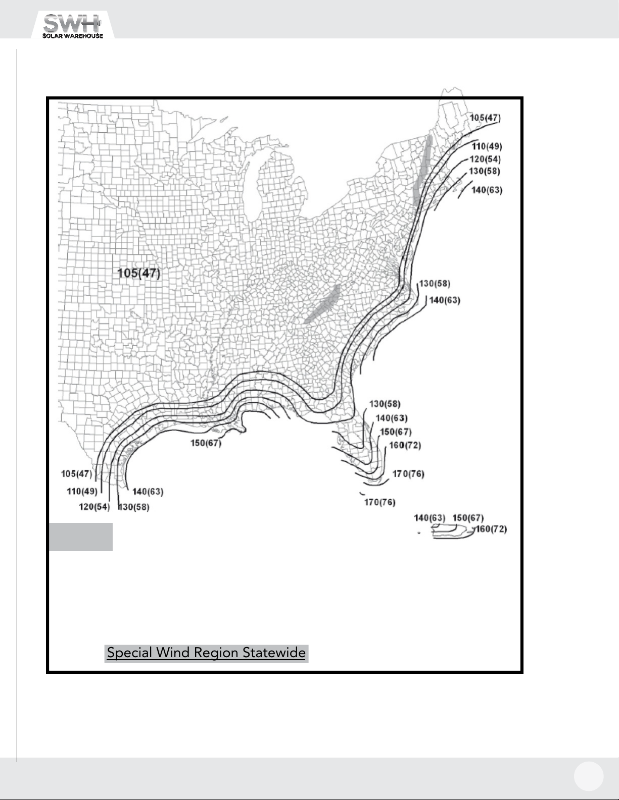
Basic Wind Speed = V (mph), the largest 3 second gust of wind in
the last 50 years.
h (ft) = total roof height for flat roof buildings or mean roof height
for pitched roof buildings
Roof Pitch (degrees)
This manual will help you determine:
Effective Wind Area (sf) = minimum total continuous area of
modules being installed (Step 4)
Roof Zone = the area of the roof you are installing the pv system
according to Step 5.
Roof Zone Dimension = a (ft) (Step 5)
Exposure Category (Step 3)
The procedure to determine Design Wind Load is specified by the American Society of Civil Engineers and referenced in the
International Building Code 2012 and California Building Code 2013. For purposes of this document, the values, equations and
procedures used in this document reference ASCE 7-10, Minimum Design Loads for Buildings and Other Structures. Please refer
to ASCE 7-10 if you have any questions about the definitions or procedures presented in this manual. SWH solar racking system
uses Part 2, The Simplified Method, for low rise buildings to calculate the Design Wind Load for pressures on components and
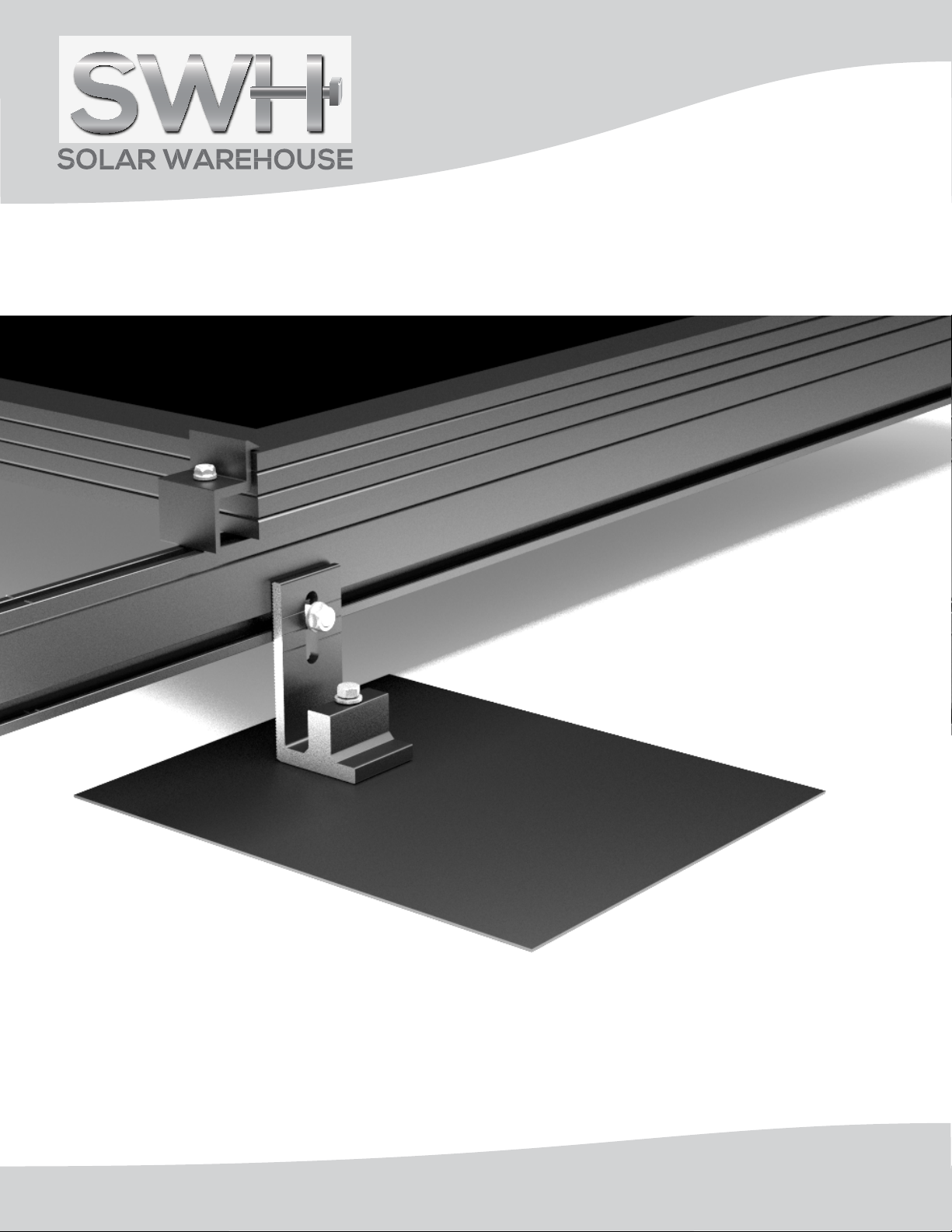
cladding in this document. The method described in this document is valid for flush, no tilt, SWH applications on either roofs or
walls. Flush is defined as panels parallel to the surface (or with no more than 3” difference between ends of assembly) with no
more than 10” space between the roof surface, and the bottom of the PV panels.
Part I. Procedure to Calculate Total Design Wind Load
4

9628 Valley Blvd. Rosemead, CA 91770 | Phone 626-579-3288 | info@esolarwarehouse.com
SWH Solar Racking Installation Guide | Version 12.10.v2
5
Step 1. Determine risk category
Buildings and other structures shall be classified, based on the risk to human life, health and
welfare associated with their damage or failure by nature of their occupancy or use. For the
purpose of applying flood, wind, snow, ice, and earthquake provisions. See Table 1 below.
I
II
III
IV
aBuildings and other structures containing toxic, highly toxic, or explosive substances shall be eligible for classification to a lower
Risk Category if it can be demonstrated to the satisfaction of the authority having jurisdiction by a hazard assessment as described
in Section 1.5.2 of ASCE 7-10 that a release of the substances is commensurate with the risk associated with that Risk Category.
Step 2. Determine the Basic Wind Speed, V (mph)
Determine the basic wind speed, V (mph) by consulting your local department or by locating
your installation on the maps in Figures 26.5-1A through 1C, pages 6 -11. Please note that
the wind speeds are dependent on the Risk (Occupancy) category determined in Step 1.
[1.2.] Procedure to Calculate Total Design Wind Load per ASCE 7-10
TABLE 1: Risk Category of Buildings and Other Structrues for Flood, Wind, Snow, Earthquake, and Ice Loads
Use or Occupancy of Buldings and Structures
Buildings and other structures that represent a low risk to human life in the event of failure.
All buildings and other structures except those listed in Risk Categories I,III, and IV
Risk Category
• Buildings and other structures designated as essential facilities.
•Buildings and other structures, the failure of which could pose a substantial hazard to the community.
• Buildings and other structures (including, but not limited to, facilities that manufacture, process, handle,
store, use, or dispose of such substances as hazardous fuels, or hazardous chemicals, or hazardous waste)
containing sufficient quantities of highly toxic substances where the quantity exceeds a threshod quantity
established by the authority having jurisdiction to be dangerous to the public if released and is sufficient to
the pose a threat to the public if released.
• Builings andother structures requried to maintain the functtionality of other Risk Category IV structures.
• Buildings and other structures, the failure of which could pose a substantial risk to human life.
• Buildings and other structures, not included in Risk Category IV, with potential to cause a substantial
economic impact and/or mass disruption of day-to-day civilian life in the event of failure.
• Buildings and other structures, not included in Risk Category IV (including, but not limited to, facilities
that manufacture, process, handle, store, use, or dispose of such substances as hazardous fuels, hazardous
chemicals, hazardous waste, or explosives) containing toxic or explosive substances where their quantity
exceeds a threshold quantity established by authority having jurisdiction and is sufficient to pose a threat ot
the public if released.

9628 Valley Blvd. Rosemead, CA 91770 | Phone 626-579-3288 | info@esolarwarehouse.com
SWH Solar Racking Installation Guide | Version 12.10.v2
6
Source: ASCE 7-10 Minimum Design Loads for
Buildings and Other Structures, Chapter 26
Notes:
1. Values are design 3-second gust wind speeds in miles per hour (m/s) at 33 ft (10m) above ground for Exposure C category.
2. Linear interpolation between contours is permitted.
3. Islands and coastal areas outside the last contour shall use the last wind speed contour of the coastal area.
4. Mountainous terrain, gorges, ocean promontories, and special wind regions shall be examined for unusual wind conditions.
5. Wind speeds correspond to approximately a 7% probability of exceedance in 50 years (annual exceedance probability = 0.00143,
MRI = 700 years).
Miles per hour (Meters per second)
[1.2.] Procedure to Calculate Total Design Wind Load per ASCE 7-10
FIGURE 26.5-1A Basic Wind Speeds for Risk Category II Buildings and Other Structures

9628 Valley Blvd. Rosemead, CA 91770 | Phone 626-579-3288 | info@esolarwarehouse.com
SWH Solar Racking Installation Guide | Version 12.10.v2
7
Source: ASCE 7-10 Minimum Design Loads for
Special Wind Region
Location
Guam
Virgin Islands
America Samoa
Hawaii- Special Wind Region Statewide
Buildings and Other Structures, Chapter 26
Miles per hour
(Meters per second)
[1.2.] Procedure to Calculate Total Design Wind Load per ASCE 7-10
Vmph
195
165
160
130
(m/s)
(87)
(74)
(72)
(58)
FIGURE 26.5-1A (Continued) Basic Wind Speeds for Risk Category II Buildings and Other Structures

9628 Valley Blvd. Rosemead, CA 91770 | Phone 626-579-3288 | info@esolarwarehouse.com
SWH Solar Racking Installation Guide | Version 12.10.v2
8
Notes:
1. Values are design 3-second gust wind speeds in miles per hour (m/s) at 33 ft (10m) above ground for Exposure C category.
2. Linear interpolation between contours is permitted.
3. Islands and coastal areas outside the last contour shall use the last wind speed contour of the coastal area.
4. Mountainous terrain, gorges, ocean promontories, and special wind regions shall be examined for unusual wind conditions.
5. Wind speeds correspond to approximately a 3% probability of exceedance in 50 years (annual exceedance probability =
0.000588, MRI = 1700 years).
Miles per hour (Meters per second)
Source: ASCE 7-10 Minimum Design Loads for
Buildings and Other Structures, Chapter 26
[1.2.] Procedure to Calculate Total Design Wind Load per ASCE 7-10
FIGURE 26.5-1B Basic Wind Speeds for Risk Category III and IV Buildings and Other Structures

8
9628 Valley Blvd. Rosemead, CA 91770 | Phone 626-579-3288 | info@esolarwarehouse.com
SWH Solar Racking Installation Guide | Version 12.10.v2
Source: ASCE 7-10 Minimum Design Loads for
Special Wind Region
Location
Guam
Virgin Islands
America Samoa
Hawaii- Special Wind Region Statewide
Buildings and Other Structures, Chapter 26
[1.2.] Procedure to Calculate Total Design Wind Load per ASCE 7-10
Vmph
180
150
150
115
(m/s)
(80)
(67)
(67)
(51)
Puerto Rico
FIGURE 26.5-1B (Continued) Basic Wind Speeds for Risk Category III and IV Buildings and Other Structures
Miles per hour
(Meters per second)
9

9628 Valley Blvd. Rosemead, CA 91770 | Phone 626-579-3288 | info@esolarwarehouse.com
SWH Solar Racking Installation Guide | Version 12.10.v2
Source: ASCE 7-10 Minimum Design Loads for
Buildings and Other Structures, Chapter 26
[1.2.] Procedure to Calculate Total Design Wind Load per ASCE 7-10
Notes:
1. Values are design 3-second gust wind speeds in miles per hour (m/s) at 33 ft (10m) above ground for Exposure C category.
2. Linear interpolation between contours is permitted.
3. Islands and coastal areas outside the last contour shall use the last wind speed contour of the coastal area.
4. Mountainous terrain, gorges, ocean promontories, and special wind regions shall be examined for unusual wind conditions.
5. Wind speeds correspond to approximately a 15% probability of exceedance in 50 years (annual exceedance probability =
0.00333, MRI = 300 years).
Miles per hour (Meters per second)
FIGURE 26.5-1C Basic Wind Speeds for Risk Category I Buildings and Other Structures
10

9628 Valley Blvd. Rosemead, CA 91770 | Phone 626-579-3288 | info@esolarwarehouse.com
SWH Solar Racking Installation Guide | Version 12.10.v2
Source: ASCE 7-10 Minimum Design Loads for
Special Wind Region
Location
Guam
Virgin Islands
America Samoa
Hawaii- Special Wind Region Statewide
Buildings and Other Structures, Chapter 26
[1.2.] Procedure to Calculate Total Design Wind Load per ASCE 7-10
Vmph
180
150
150
115
(m/s)
(80)
(67)
(67)
(51)
Puerto Rico
Miles per hour
(Meters per second)
FIGURE 26.5-1C (Continued) Basic Wind Speeds for Risk Category I Buildings and Other Structures
11

9628 Valley Blvd. Rosemead, CA 91770 | Phone 626-579-3288 | info@esolarwarehouse.com
SWH Solar Racking Installation Guide | Version 12.10.v2
192a STANDARDS 7-10
[1.2.] Procedure to Calculate Total Design Wind Load per ASCE 7-10
Step 3. Determine Wind Load Parameters
Step 3a:Determine the proper Exposure
Category (B, C, or D) for the project by
using the following definitions for Surface
Roughness Categories.
ASCE 7-10 defines wind surface
roughness categories as follows:
Surface Roughness B: Urban and suburban
areas, wooded areas, or other terrain with
numerous closely spaced obstructions
having the size of single-family dwellings
or larger.
Surface Roughness C: Open terrain with
scattered obstructions having heights
grasslands.
Surface Roughness D: Flat, unobstructed
areas and water surfaces. This category
includes smooth mud flats, salt flats, and
unbroken ice.
Step 3b:Determine the Topographic
Factor, Kzt
.
For the purposes of this code compliance
document, the Topographic Factor, Kzt, is
taken as equal to one (1) as per Section
26.8-2 or as determined by Figure 26.8-1
in ASCE 7-10. Also shown in pages 13-14`.
Step 4. Determine Effective Wind Area
Determine the smallest area
of continuous modules you will be
installing. This is the smallest area
tributary (contributing load) to a support
or to a simple-span of rail. That area is
the Effective Wind Area, the total area of
the fewest number of modules on a run
of rails. If the smallest area of continuous
modules exceeds 100 sq ft, use 100 sq ft,
if less round down to values available in
Table 3, page 17.
Step 5. Determine the appropriate roof
zone for the installation.
The Design Wind Load will vary
based on where the installation is located
on a roof. Arrays may be located in more
than one roof zone.
Using Table 2, page 15, determine the
Roof Zone Dimension Length, a (ft) ,
according to the width and height of the
building on which you are installing the pv
system.
category includes flat open country and
generally less than 30 ft (9.1 m). This
12

9628 Valley Blvd. Rosemead, CA 91770 | Phone 626-579-3288 | info@esolarwarehouse.com
SWH Solar Racking Installation Guide | Version 12.10.v2
[1.2.] Procedure to Calculate Total Design Wind Load per ASCE 7-10
Topographic Factor, K zt
Topographic Multipliers for Exposure C
K1Multiplier K2Multiplier K3Multiplier
H/Lh2-D
Ridge
2-D
Escarp.
3-D
Axisym.
Hill
x/Lh2-D
Escarp.
All
Other
Cases
z/Lh2-D
Ridge
2-D
Escarp.
3-D
Axisym.
Hill
0.20 0.29 0.17 0.21 0.00 1.00 1.00 0.00 1.00 1.00 1.00
0.25 0.36 0.21 0.26 0.50 0.88 0.67 0.10 0.74 0.78 0.67
0.30 0.43 0.26 0.32 1.00 0.75 0.33 0.20 0.55 0.61 0.45
0.35 0.51 0.30 0.37 1.50 0.63 0.00 0.30 0.41 0.47 0.30
0.40 0.58 0.34 0.42 2.00 0.50 0.00 0.40 0.30 0.37 0.20
0.45 0.65 0.38 0.47 2.50 0.38 0.00 0.50 0.22 0.29 0.14
0.50 0.72 0.43 0.53 3.00 0.25 0.00 0.60 0.17 0.22 0.09
3.50 0.13 0.00 0.70 0.12 0.17 0.06
4.00 0.00 0.00 0.80 0.09 0.14 0.04
0.90 0.07 0.11 0.03
1.00 0.05 0.08 0.02
1.50 0.01 0.02 0.00
2.00 0.00 0.00 0.00
Notes:
1. For values of H/Lh, x/Lhand z/Lhother than those shown, linear interpolation is permitted.
2. For H/Lh> 0.5, assume H/Lh= 0.5 for evaluating K1and substitute 2H for Lhfor evaluating K2and K3.
3. Multipliers are based on the assumption that wind approaches the hill or escarpment along the
direction of maximum slope.
4. Notation:
H: Height of hill or escarpment relative to the upwind terrain, in feet (meters).
Lh: Distance upwind of crest to where the difference in ground elevation is half the height of hill or
escarpment, in feet (meters).
K1: Factor to account for shape oftopographic feature and maximum speed-up effect.
K2: Factor to account for reduction in speed-up with distance upwind or downwind ofcrest.
K3: Factor to account for reduction in speed-up with height above local terrain.
x: Distance (upwind or downwind) from the crest to the building site, in feet (meters).
z: Height above ground surface at building site, in feet (meters).
μ: Horizontal attenuation factor.
γ: Height attenuation factor.
Source: ASCE-7-10 Chapter 26, page 26
Figure 26.8-1 WIND LOADS: GENERAL REQUIREMENTS
13

9628 Valley Blvd. Rosemead, CA 91770 | Phone 626-579-3288 | info@esolarwarehouse.com
SWH Solar Racking Installation Guide | Version 12.10.v2
[1.2.] Procedure to Calculate Total Design Wind Load per ASCE 7-10
Source: ASCE-7-10 Chapter 26, page 253
Figure 26.8-1 (cont’d) WIND LOADS: GENERAL REQUIREMENTS
Topographic Factor, Kzt
Equations:
2
321zt )KKK(1K +=
belowtablefromdeterminedK1
)
L
x
-(1K
h
2μ
=
h
z/L-
3eK
γ
=
Parameters for Speed-Up Over Hills and Escarpments
K1/(H/Lh)m
Hill Shape Exposure
g
Upwind Downwind
B C D of Crest of Crest
2-dimensional ridges
(or valleys with negative
H in K1/(H/Lh)1.30 1.45 1.55 3 1.5 1.5
2-dimensional escarpments 0.75 0.85 0.95 2.5 1.5 4
3-dimensional axisym. hill 0.95 1.05 1.15 4 1.5 1.5
14

10
9628 Valley Blvd. Rosemead, CA 91770 | Phone 626-579-3288 | info@esolarwarehouse.com
SWH Solar Racking Installation Guide | Version 12.10.v2
192a STANDARDS 7-10
Table 2. Determine Roof/Wall Zone dimension (a) according to building width and height
a = 10 percent of the least horizontal dimension or 0.4h whichever is smaller, but not less than either 4% of the least
horizontal dimension or 3 ft of the building.
Roof
Height (ft) 10
3
3
3
3
3
3
3
3
3
3
15
3
3
3
3
3
3
3
3
3
3
20
3
3
3
3
3
3
3
3
3
3
25
3
3
3
3
3
3
3
3
3
3
30
3
3
3
3
3
3
3
3
3
3
40
4
4
4
4
4
4
4
4
4
4
50
4
5
5
5
5
5
5
5
5
5
60
4
6
6
6
6
6
6
6
6
6
70
4
6
7
7
7
7
7
7
7
7
80
4
6
8
8
8
8
8
8
8
8
90
4
6
8
9
9
9
9
9
9
9
100
4
6
8
10
10
10
10
10
10
10
125
5
6
8
10
12
12.5
12.5
12.5
12.5
12.5
150
6
6
8
10
12
14
15
15
15
15
175
7
7
8
10
12
14
16
17.5
17.5
17.5
200
8
8
8
10
12
14
16
18
20
20
10
15
20
25
30
35
40
45
50
60
[1.2.] Procedure to Calculate Total Design Wind Load per ASCE 7-10
Step 5. Determine the appropriate roof zone for the installation (continued)
Using the Roof Zone Dimension Length, a, determine the roof zone locations according to your roof
type, gable, hip or monoslope. Determine in which roof zone your pv system is located, Zone 1, 2,
or 3 according to Figure 3, page 16.
300
12
12
12
12
12
14
16
18
20
24
400
16
16
16
16
16
16
16
18
20
24
500
20
20
20
20
20
20
20
20
20
24
Least Horizontal Dimensions (ft)
15

9628 Valley Blvd. Rosemead, CA 91770 | Phone 626-579-3288 | info@esolarwarehouse.com
SWH Solar Racking Installation Guide | Version 12.10.v2
192a STANDARDS 7-10
[1.2.] Procedure to Calculate Total Design Wind Load per ASCE 7-10
Step 6. Determine Net Design Wind
Pressure, pnet30 (psf)
Using the Effective Wind Area (Step 4), Roof
Zone Location (Step 5), and Basic Wind
Speed (Step 2), look up the appropriate
Net Design Wind Pressure in Table 3, page
17. Use the Effective Wind Area value in
the table which is smaller than the value
calculated in Step 2. If the installation is
Figure 3. Enclosed buildings, wall and roofs
Flat Roof Hip Roof (7˚ < θ≤ 27°)
Gable Roof ( θ≤ 7°) Gable Roof (7˚ < θ≤ 45°)
Interior Zones
Roofs - Zone 1/Walls - Zone 4
End Zones
Roofs - Zone 2/Walls - Zone 5
Corner Zones
Roofs - Zone 3
Source: ASCE/SEI 7-10, Minimum Design Loads for Buildings and Other Structures, Chapter 30, p. 345.
h
a
aa
ah
a
a
a
a
a TYP
h
a
a
a
a
h
a
a
a
a
located on a roof overhang, use Table 4, page
18. Both downforce and uplift pressures must
be considered in overall design. Refer to Section
II, Step 1 for applying downforce and uplift
pressures. Positive values are acting toward the
surface. Negative values are acting away from
the surface.
16

9628 Valley Blvd. Rosemead, CA 91770 | Phone 626-579-3288 | info@esolarwarehouse.com
SWH Solar Racking Installation Guide | Version 12.10.v2
[1.2.] Procedure to Calculate Total Design Wind Load per ASCE 7-10
Table 3. pnet30 (psf) Roof and Wall
17

9628 Valley Blvd. Rosemead, CA 91770 | Phone 626-579-3288 | info@esolarwarehouse.com
SWH Solar Racking Installation Guide | Version 12.10.v2
[1.2.] Procedure to Calculate Total Design Wind Load per ASCE 7-10
Table 4. p net30 (psf) Roof Overhang
Step 7. Determine adjustment factor for height and exposure category, l
Using the Exposure Category (Step 3) and the roof height, h (ft), look up the adjustment
factor for height and exposure (λ) in Table 5, page 19.
Roof Overhang Net Design Wind Pressure, Pnet30 (psf)
Zone Effective
wind area
(sf)
Basic Wind Speed V (mph)
110 115 130 140 150 160 180 200
(Exposure B at h=30 ft.)
2
2
2
2
3
3
3
3
10
20
50
100
10
20
50
100
-36.9
-35.8
-34.3
-33.2
-36.9
-35.8
-34.3
-33.2
-40.3
-39.1
-37.5
-36.3
-40.3
-39.1
-37.5
-36.3
-51.5
-50.0
-47.9
-46.4
-51.5
-50.0
-47.9
-46.4
-59.8
-58.0
-55.6
-53.8
-59.8
-58.0
-55.6
-53.8
-68.6
-66.5
-63.8
-61.7
-68.6
-66.5
-63.8
-61.7
-78.1
-75.7
-72.6
-70.2
-78.1
-75.7
-72.6
-70.2
-98.8
-95.8
-91.9
-88.9
-98.8
-95.8
-91.9
-88.9
-122.0
-118.3
-113.4
-109.8
-122.0
-118.3
-113.4
-109.8
-40.6
-40.6
-40.6
-40.6
-68.3
-61.6
-52.8
-46.1
-44.4
-44.4
-44.4
-44.4
-74.6
-67.3
-57.7
-50.4
-56.7
-56.7
-56.7
-56.7
-95.3
-86.0
-7.7
-64.4
-65.7
-65.7
-65.7
-65.7
-110.6
-99.8
-85.5
-74.7
-75.5
-75.5
-75.5
-75.5
-126.9
-114.5
-98.1
-85.8
-108.7
-108.7
-108.7
-108.7
-182.8
-164.9
-141.3
-123.5
-134.2
-134.2
-134.2
-134.2
-225.6
-203.6
-174.5
-152.4
-85.9
-85.9
-85.9
-85.9
-144.4
-130.3
-111.7
-97.6
-31.4
-30.8
-30.1
-29.5
-51.6
-40.5
-25.9
-14.8
-34.3
-33.7
-32.9
-32.3
-56.5
-44.3
-28.3
-16.1
-43.8
-43.0
-42.0
-41.2
-72.1
-56.6
-36.1
-20.6
-50.8
-49.9
-48.7
-47.8
-83.7
-65.7
-41.9
-23.9
-58.3
-57.3
-55.9
-54.9
-96.0
-75.4
-48.1
-27.4
-66.3
-65.2
-63.6
-62.4
-109.3
-85.8
-54.7
-31.2
-84.0
-82.5
-80.5
-79.0
-138.3
-108.6
-69.3
-39.5
-103.7
-101.8
-99.4
-97.6
-170.7
-134.0
-85.5
-48.8
Roof 0 to 7 degrees
Roof 7 to 27 degrees
Roof > 27 to 45 degrees
2
2
2
2
3
3
3
3
10
20
50
100
10
20
50
100
10
20
50
100
10
20
50
100
2
2
2
2
3
3
3
3
18

9628 Valley Blvd. Rosemead, CA 91770 | Phone 626-579-3288 | info@esolarwarehouse.com
SWH Solar Racking Installation Guide | Version 12.10.v2
[1.2.] Procedure to Calculate Total Design Wind Load per ASCE 7-10
Step 8. Calculate the adjusted wind pressures, pnet , (psf)
Multiply the Net Design Wind Pressure, pnet30 by the adjustment factor for height and
exposure, l, the Topographic Factor, Kzt.
Where
l= adjustment factor for building height and exposure (Step 7)
Kzt = For the purposes of this code compliance document, the Topographic Factor, Kzt , is
taken as equal to one (1) as per Section 26.8-2 or as determined by Figure 26.8-1 in ASCE
7-10.
Pnet30 = net design wind pressure for Exposure B, at h = 30 ft (Step 6)
The adjusted wind pressures will be used to select the appropriate SWH rail, rail span
and attachment spacing.
Use both the positive (downforce) and the negative (uplift) results from this calculation.
Table 5. Adjustment Factor ( ) for Roof Height & Exposure Category
Mean roof height (ft)
Exposure
B
15
20
25
30
35
40
45
50
55
60
1.00
1.00
1.00
1.00
1.05
1.09
1.12
1.16
1.19
1.22
1.21
1.29
1.35
1.40
1.45
1.49
1.53
1.56
1.59
1.62
1.47
1.55
1.61
1.66
1.70
1.74
1.78
1.81
1.84
1.87
C D
l
19

9628 Valley Blvd. Rosemead, CA 91770 | Phone 626-579-3288 | info@esolarwarehouse.com
SWH Solar Racking Installation Guide | Version 12.10.v2
20
Part II. Procedure to Select Rail Span and Foot Spacing
[2.1.] Using Standard Beam Calculations, Structural Engineering
Methodology ASCE 7-10
The procedure to determine the SWH rail span
uses standard beam calculations and structural
engineering methodology. The beam calculations
are based on a simply supported beam
conservatively, ignoring the reductions
allowed for supports of continuous beams over
multiple supports. Please refer to Part I for more
information on beam calculations, equations and
assumptions. If beams are installed
perpendicular to the eaves on a roof steeper
than a 4/12 pitch in an area with a ground snow
load greater than 30 psf, then additional analysis
is required for side loading on the roof
attachment and beam.
In using this document, obtaining correct results
is dependent upon the following:
1. Obtain the Snow Load for your area from your
local building official.
2. Obtain the Design Wind Load, pnet. See Part I
(Procedure to Determine the Design Wind Load)
for more information on calculating the Design
Wind Load.
3. Please Note: The terms rail span and footing
spacing are interchangeable in this document.
See Figure 4 for illustrations.
4. To use Table 7 the Dead Load for your
specific installation must be less than 5 psf,
including modules and SWH racking systems.
If the Dead Load is greater than 5 psf, see your
SWH distributor, a local structural engineer or
contact SWH. The following procedure will guide
you in selecting a SWH rail for a flush mount
installation. It will also help determine the design
loading imposed by the SWH PV Mounting
Assembly that the building structure must be
capable of supporting.
P (psf) = 1.0D + 1.0S 1(downforce case 1)
P (psf) = 1.0D + 0.6 p net
(downforce case 2)
P (psf) = 1.0D + 0.75S 1+ 0.75(0.6p net)
(downforce case 3)
P (psf) = 0.6D + 0.6 pnet (uplift)
D = Dead Load (psf)
S = Snow Load (psf)
pnet = Design Wind Load (psf) (Positive for downforce,
negative for uplift)
Description Variable Downforce Case 1 Downforce Case 2 Downforce Case 3 Uplift units
Dead Load D 1.0 x 1.0 x 1.0 x 0.6 x psf
Snow Load S 1.0 x + 0.75 x + psf
Design Wind Load Pnet 0.6 x + 0.75 x + 0.6 x - psf
Total Design Load P psf
Table 6. ASCE 7-10 Load Combinations
Note: Table to be filled out or attached for evaluation.
Step 1. Determine the Total Design Load
The Total Design Load, P (psf) is determined
using ASCE 7-10 2.4.1 (ASD Method equations 3,
5, 6a and 7) by adding the Snow Load, S (psf),
Design Wind Load, Pnet (Psf) Step 8 page 19 and
the Dead Load (psf). Both Uplift and Downforce
Wind Loads calculated in Step 8, Page 19 of
section 1.2. must be investigated. Use Table 6 to
calculate the Total Design Load for the load
cases. Use the maximum absolute value of the
three downforce cases and the uplift case for
sizing the rail. Use the uplift case only for sizing
lag bolts pull out capacities. Use the following
equations or Table 6, below.
Table of contents