manuals.online logo
Brands
  1. Home
  2. •
  3. Brands
  4. •
  5. Swing
  6. •
  7. Aircraft
  8. •
  9. Swing Mistral 5 User manual

Swing Mistral 5 User manual

Instructions: how to attach the Mistral 5 paramotor risers
In this guide we describe how to set up your Mistral 5 with paramotor risers.
Please take extreme care when you are doing this and double-check everything one final
time when you have finished.
Caution: After you have finished attaching the paramotor risers, it is essential that
you inflate your glider before you next fly it and check that everything is in
order
1. Preliminary
You will need the following items to set up your Mistral 5 with paramotor risers (Fig. 1):
1. Paramotor risers for Mistral 5. We have developed paramotor risers specifically for the
Mistral 5. These are very different from paramotor risers for other models of paraglider. A
quick-link with an O-ring is attached to the right-hand B-riser. This should make it easier
for you to change the risers and will be left over once you have finished.
2. Your Mistral 5
3. A small spanner (7mm wide) to open the quick links
4. A place to hang up the risers
5. These instructions
Fig. 1: Items required
2. How to change over the risers
We recommend that you hang up the risers in pairs beside one another when you change
them over i.e. the two right-hand risers together and then the two left-hand risers together
(see Fig. 2).
Fig. 2: risers hanging up
Check that you have the correct pairs of riser hanging up together before you start to change
them over. You have done this correctly if the brake pulleys are facing in the same direction
(Fig. 3).
Standard riser with
lines Paramotor riser with
quick link on B
Pulleys on the right-
hand side
Fig. 3: The two right-hand risers
Begin with the right-hand risers. First, you need to attach all of the lines from the right-hand
standard riser to the right-hand paramotor riser. You then need to attach all of the lines from
the left-hand standard riser to the left-hand paramotor riser. It is important to follow a specific
sequence as described below to do this, so that the lines are not mixed up or twisted.
2.1. Transferring the A quick links
Start with the lines on the A1 riser. Open the quick link (Fig. 4), remove it from the riser (Fig.
5) and hang it on the A1 riser of the paramotor riser, facing in the same direction (Fig. 6).
Fig. 4: Open the quick link Fig. 5: Remove the quick
link Fig. 6: Paramotor riser with
A1 quick link
Now close the quick link again and use the spanner to tighten it (Fig. 7). It has been
tightened up enough when you can no longer open it up with your fingers.
Fig. 7: Closing and tightening the quick link
Repeat the process with the lines on the A2 riser.
2.2. Transferring the stabiliser lines and the B- and C1 lines
You must transfer the stabiliser lines from the B-level to the C-level for use with the
paramotor riser. This means that you cannot simply transfer the B and C1 quick links from
one riser to the other.
Open the quick link for the B-lines and undo the O-ring (Fig. 8).
Take the inside three B-lines (blue) and hang them in the quick link on the paramotor riser
(Fig. 9 and Fig. 10).
Fig. 8: B-quick link open and showing O-
ring undone Fig. 9: Paramotor riser with B-quick link
(to the right-hand side)
Now take the shackle with the stabiliser lines and connect it to the C1 strap on the paramotor
riser (Fig. 11).
Fig. 10: Paramotor riser with B-lines Fig. 11: Paramotor riser with stabiliser
lines on C1
Next, open the C1 quick link and undo that O-ring too (Fig. 12). Now take the lines out of the
quick link and hang them with the stabiliser lines on the paramotor riser. Fasten the O-ring
and close the C1 quick link on the paramotor riser (Fig. 13).
Fig. 12: C1 quick link on the standard riser Fig. 13: Paramotor riser with C1 quick link
and both stabiliser and C1-lines
Take the empty quick link off the standard riser and put it in a safe place. You will need it
later on to change over the second riser.
2.3. Transferring the C2 quick link
The C2 quick link is transferred in the same way to the A quick link. When you have swapped
over the C2 quick link, all of the rigging lines will be on the paramotor riser. Only the brake
line will still be on the standard riser (Fig. 14).
Fig. 14: Paramotor riser with all lines, except the brake line
2.4. Transferring the brake line
You must first undo the knot on the brake handle before you are able to transfer the brake
line (Fig. 15).
Fig. 15: Brake line with the knot undone
Now remove the brake handle from the brake line and pull the brake line through the pulley.
Feed the brake line from the quick link through the upper pulley on the paramotor riser (Fig.
16).
Fig. 16: Brake line in upper pulley
Then make a loose knot in the brake line at the mark (behind the pulley, see Fig. 17).
Now attach the brake handle to the brake line again. To do this, feed the brake line through
the loop on the brake handle until just before the knot (Fig. 18). Take the free end of the
brake line, loop it back and make it into a knot with the brake line.
Fig. 17: Brake line with knot at the mark Fig. 18: Brake handle with brake line
To make the knot, feed the end of the brake line into the knot in the brake line following the
way the line is running (Fig. 19 to Fig. 21). By doing this, you will turn the single knot in the
line into a double knot which holds the brake handle firmly
.
Fig. 19: Make a knot Fig. 20: Make a knot Fig. 21: Make a knot
When making the knot, take care that the brake line is the same length as it was before. The
brake line must not be shortened.
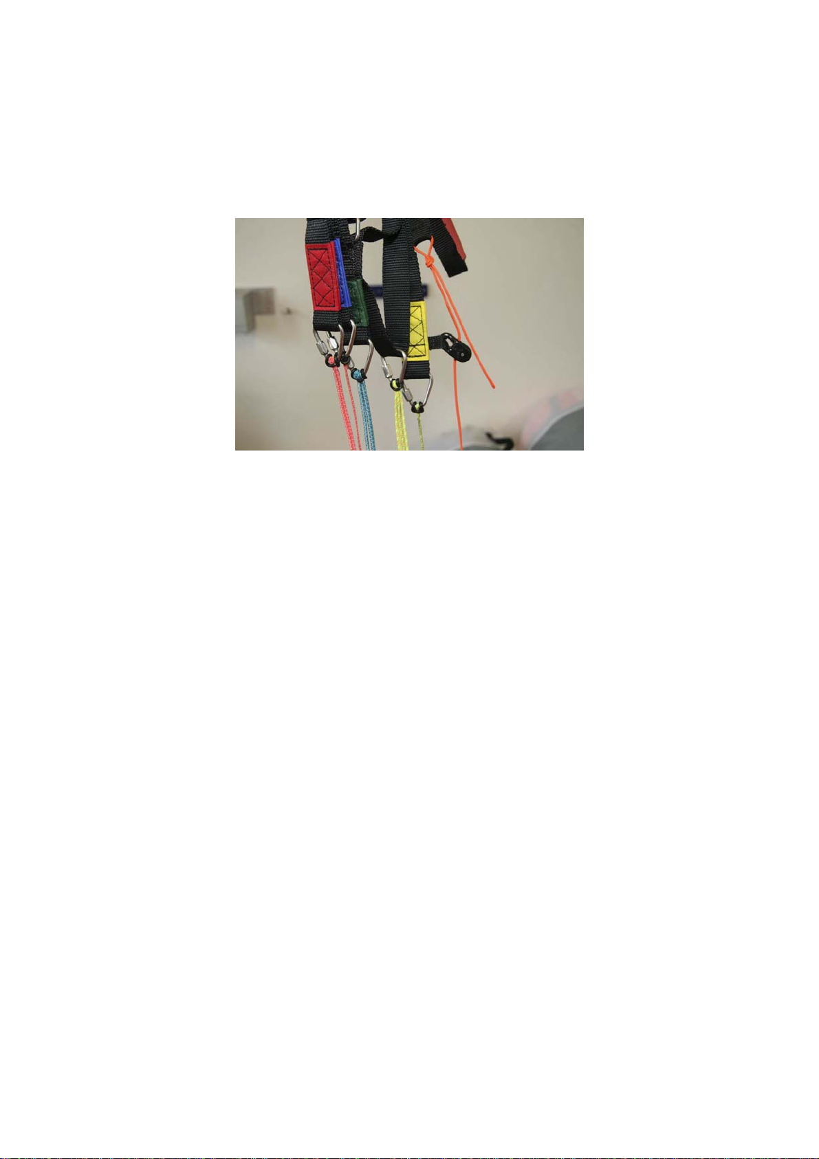
You have now changed over the first riser. All of the lines should now be on the paramotor
riser, none of them twisted and all of the quick link openings should be facing inwards (away
from the brake pulley). Check once again that you have also correctly attached the stabiliser
lines to C1. Your paramotor riser should now look like the picture in Fig. 22.
Fig. 22: Paramotor riser with all main lines and brake lines (the right-hand riser is shown
here)
If the brake handles are extremely high up and difficult to reach when used with a motor, it is
also possible to feed the brake lines through the lower pulley in motorised use.
To do this, it is essential that you lengthen the brake lines by the distance between the
pulleys (18.5cm). This requires a longer main brake line, which you are able to obtain from
us for your paramotor riser. The longer brake line generally already has a second mark for
the lower pulley. If this is not the case, make a second mark on the brake line, 20cm below
the original mark (towards the end of the line).
We would like to point out to you once again that the brake lines must not be shortened,
as this can cause dangerous changes in flight behaviour and extreme flight behaviour.
2.5. Preparation of the second side
After you have finished changing over the first riser correctly, hang up the two risers for the
other side next to one another. Hang the quick link which you previously put to one side onto
the B-riser with the open side facing inwards (the side away from the pulley).
You are now ready to change over the second riser in the same way as the first riser.
3. Check
When you have finished changing over the riser, there should be two standard risers and one
quick link with O-ring left over.
It is essential that you check the following after the risers have been changed over:
3.1. Lines correct
The lines must not be twisted. The quick links must be attached to the correct riser and the
stabiliser lines must now be attached to the C1 quick link. The brake pulleys must be facing
outwards. The brake line must be running through the upper pulley.
3.2. Quick links closed
When this has all been done correctly, make sure that all of the quick links have been
tightened firmly so they do not open accidentally. The best way to do this is to check them
again lightly with the spanner.
3.3. Inflate the glider
After you have changed over the risers, it is imperative that you inflate the glider on a flat
area before you next fly it and check once again that all of the lines are clear. You should
also check at the same time that the brakes are symmetrical and adjusted to the right length.
4. Final words
We hope that you have many memorable flights with your Mistral 5, whether you are flying in
the mountains, on winch or with a motor.
Always remember to put the risers back to the DHV configuration when you are not flying
with a motor, as this is how it was tested for certification and certification will otherwise be
void.
If you have any other questions or are having difficulty changing over the risers, please
telephone us on (+49) 81413277888 or write to us at [email protected].
The SWING Team

Other Swing Aircraft manuals

Swing NYOS RS User manual

Swing

Swing NYOS RS User manual

Swing CONNECT REVERSE 3 User manual

Swing

Swing CONNECT REVERSE 3 User manual

Swing Powerplay Scorpio User manual

Swing

Swing Powerplay Scorpio User manual

Swing Spitfire User manual

Swing

Swing Spitfire User manual

Swing Astral 6 User manual

Swing

Swing Astral 6 User manual

Swing Spitfire 2 User manual

Swing

Swing Spitfire 2 User manual

Swing TWIN RS 2 Series User manual

Swing

Swing TWIN RS 2 Series User manual

Swing MITO User manual

Swing

Swing MITO User manual

Swing APUS RS 14 User manual

Swing

Swing APUS RS 14 User manual

Swing MIURA RS User manual

Swing

Swing MIURA RS User manual

Swing NYOS RS User manual

Swing

Swing NYOS RS User manual

Swing Discus User manual

Swing

Swing Discus User manual

Swing ars Cirrus 2 User manual

Swing

Swing ars Cirrus 2 User manual

Swing Escape User manual

Swing

Swing Escape User manual

Swing HYBRID SPORT User manual

Swing

Swing HYBRID SPORT User manual

Swing RAST Mirage RS 2 User manual

Swing

Swing RAST Mirage RS 2 User manual

Swing MIRAGE2 RS User manual

Swing

Swing MIRAGE2 RS User manual

Swing Nexus User manual

Swing

Swing Nexus User manual

Swing Twin RS User manual

Swing

Swing Twin RS User manual

Swing Core 3 User manual

Swing

Swing Core 3 User manual

Swing Protect III User manual

Swing

Swing Protect III User manual

Swing Spitfire 2 User manual

Swing

Swing Spitfire 2 User manual

Swing Astral 3 User manual

Swing

Swing Astral 3 User manual

Swing Powerplay Sting 2 User manual

Swing

Swing Powerplay Sting 2 User manual

Popular Aircraft manuals by other brands

Cessna 150 STANDARD Service manual

Cessna

Cessna 150 STANDARD Service manual

Pipistrel Sinus 912 LSA LSA-GLIDER Pilot operating handbook

Pipistrel

Pipistrel Sinus 912 LSA LSA-GLIDER Pilot operating handbook

Aquila AT01 owner's manual

Aquila

Aquila AT01 owner's manual

Piper CHEROKEE 180 E Owner's handbook

Piper

Piper CHEROKEE 180 E Owner's handbook

Champion 7EC Operating and service manual

Champion

Champion 7EC Operating and service manual

Pro Built GILES 202 Assembly instructions

Pro Built

Pro Built GILES 202 Assembly instructions

Skywalk TEQUILA6 Pro Guide

Skywalk

Skywalk TEQUILA6 Pro Guide

Nova PHOR2 manual

Nova

Nova PHOR2 manual

Cabrinha Kites Contra 2005 manual

Cabrinha Kites

Cabrinha Kites Contra 2005 manual

Remos GX eLITE Pilot operating handbook

Remos

Remos GX eLITE Pilot operating handbook

Ozone MAGMAX 2 Pilot's manual

Ozone

Ozone MAGMAX 2 Pilot's manual

Europa Aircraft XS Monowheel Motorglider owner's manual

Europa Aircraft

Europa Aircraft XS Monowheel Motorglider owner's manual

Hoffman DIMONA H 36 Flight manual

Hoffman

Hoffman DIMONA H 36 Flight manual

Cessna 172 1964 Ownersmanual

Cessna

Cessna 172 1964 Ownersmanual

Dudek Nemo 4 Series manual

Dudek

Dudek Nemo 4 Series manual

Opale-Paramodels backpack user guide

Opale-Paramodels

Opale-Paramodels backpack user guide

DG Flugzeugbau DG-800A Flight manual

DG Flugzeugbau

DG Flugzeugbau DG-800A Flight manual

Opale-Paramodels Trike M user guide

Opale-Paramodels

Opale-Paramodels Trike M user guide

manuals.online logo
manuals.online logoBrands
  • About & Mission
  • Contact us
  • Privacy Policy
  • Terms and Conditions

Copyright 2025 Manuals.Online. All Rights Reserved.