SWT UVL Series Instruction manual

Safe W a t e r t echnologieS, i n c .
INSTALLATION, OPERATION, MAINTENANCE MANUAL
NOV 2020
UVL SERIES
ULTRAVIOLET WATER TREATMENT SYSTEM
Made in USA
1 to 4 lamps
(SS upgrade)
3 to 4 lamps
1 to 2 lamps

TABLE OF CONTENTS
SafetyInstructions ......................................................................... 4
1) Information ........................................................................... 4
2) AboutUltraviolet(UV)Disinfection ........................................................ 4
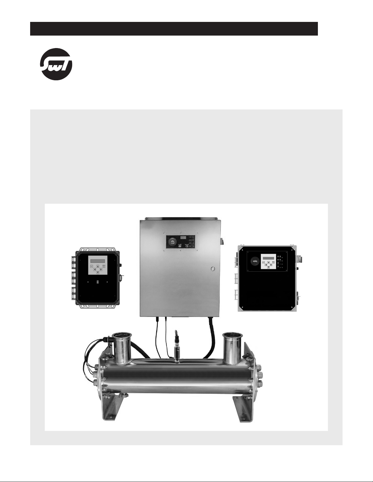
3) MajorComponents .................................................................... 5
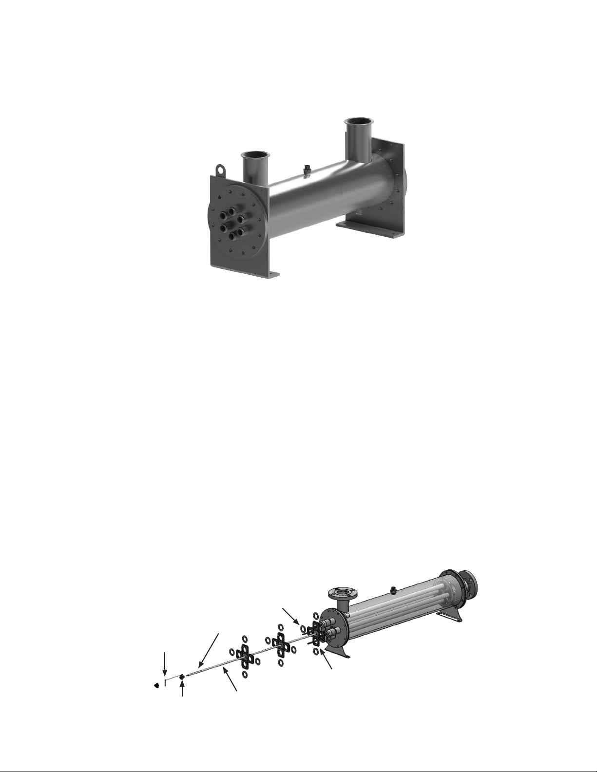
a) DisinfectionChamber ............................................................... 5
b) LampsandQuartzSleeves ........................................................... 5
c) ManualQuartzSleeveWiperSystem................................................... 5
d) ElectronicControlCenter(ECC) ...................................................... 6
4) PreparationForInstallingUVSystem ...................................................... 8
a) WaterQuality ...................................................................... 8
b) ImportantSafetyInformation ......................................................... 8
c) OptimizingSystemPerformance ...................................................... 9
d) EnvironmentalIssuesRelatingtoUVLamps ............................................. 9
e) ReceivingUVEquipmentandSpareParts .............................................. 9
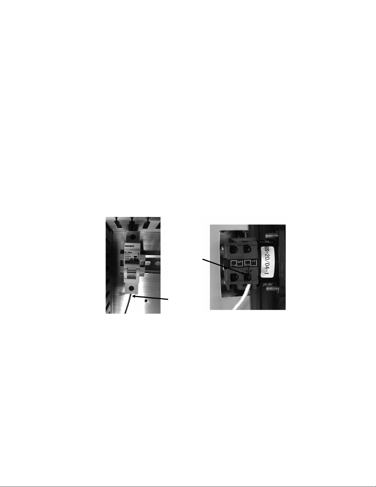
f) Electrical Configuration and Maintenance . . . . . . . . . . . . . . . . . . . . . . . . . . . . . . . . . . . . . . . . . . . . . 9
5) Installation . . . . . . . . . . . . . . . . . . . . . . . . . . . . . . . . . . . . . . . . . . . . . . . . . . . . . . . . . . . . . . . . . . . . . . . . . . . 10
a) ElectronicControlCenter(ECC) ..................................................... 10
b) HandsOffAutoSwitchWiring ........................................................ 11
c) LampOutAlert(Optional) .......................................................... 12
d) Chamber......................................................................... 12
e) SensorProbeInstallation ............................................................ 12
f) Quartz Sleeve Installation for Open Ended Sleeves . . . . . . . . . . . . . . . . . . . . . . . . . . . . . . . . . . . . . . 13
g) Lamp and Lamp Harness Bracket Installation . . . . . . . . . . . . . . . . . . . . . . . . . . . . . . . . . . . . . . . . . . . 15
6) Electronic Control Center (ECC) Operation and Moinitoring . . . . . . . . . . . . . . . . . . . . . . . . . . . . . . . . . 16
a) On/OffSwitch ..................................................................... 16
b) LampStatus....................................................................... 16
c) RuntimeMonitoring ................................................................ 17
d) Viewport ......................................................................... 17
e) ManualQuartzSleeveWiperSystem.................................................. 17
f) LampOutAlert(Optional) .......................................................... 17
g) StandardUVMonitor(Optional) ..................................................... 18
h) StandardHighHeatSensor(Optional) ................................................ 20

TABLE OF CONTENTS (CONTINUED)
7) Maintenance......................................................................... 21
a) LampMaintenance................................................................ 21
b) QuartzSleeveMaintenance......................................................... 21
c) Manual Quartz Sleeve Wiper System Maintenance . . . . . . . . . . . . . . . . . . . . . . . . . . . . . . . . . . . . . . 22
d) ECCMaintenance................................................................. 22
e) ViewportMaintenance ............................................................. 22
f) HighHeatShutoffMaintenance...................................................... 23
g) SensorProbeMaintenance ......................................................... 23
h) ChamberMaintenance ............................................................ 24
8) WaterSampling(ForFlangeModels) ..................................................... 26
a) Sampling Valves . . . . . . . . . . . . . . . . . . . . . . . . . . . . . . . . . . . . . . . . . . . . . . . . . . . . . . . . . . . . . . . . . . . 26
b) SamplingProcedure ............................................................... 26
9) FoodandDrugAdministrationStatement................................................. 27
10)HeatSanitizatiion ..................................................................... 27
UVL Series Short Chambered Systems Replacement Parts . . . . . . . . . . . . . . . . . . . . . . . . . . . . . . . . . . . . . . 28
UVL Series Long Chambered Systems Replacement Parts . . . . . . . . . . . . . . . . . . . . . . . . . . . . . . . . . . . . . . 29
UVL Series Electrical Enclosure Replacement Parts . . . . . . . . . . . . . . . . . . . . . . . . . . . . . . . . . . . . . . . . . . . . 30
Troubleshooting .......................................................................... 31
MaintenanceLog ........................................................................ 32

4
SAFETY INSTRUCTIONS
In order to protect end users and operators from injury, safety precautions must be followed.This
Installation, Operation and Maintenance (IOM) Manual outlines important safety issues.
1) INFORMATION
Please read this manual prior to installing, starting up, and operating the equipment. The equipment
uses the latest in UV technology, and has been designed to make operation and maintenance easy.
The quality of the liquid entering the UV system needs to be monitored. Based on water quality, the
UV system will need to be cleaned on a periodic basis. Maintenance of the UV system will require
replacement parts. It is suggested that key spare and replacement parts be kept on hand. For best
operation, always use manufacturer recommended replacement parts. Other replacement parts
could result in damage to the system and void the warranty.
2) ABOUT ULTRAVIOLET (UV) DISINFECTION
The technology uses UV light to target and disable disease-causing microorganisms and pathogens.
Over 100 years ago, scientists discovered that if you exposed pathogens to UV light, their
reproduction was limited. The UV light source they used resided in the UVC range of the light
spectrum. Specifically, they discovered that light in the 254 nanometer (NM) range was the most
effective wavelength for this process.
When many pathogens are exposed to UV light, their cells become damaged and this damage
inhibits reproduction.The UV light, produced by a special UV lamp, damages the cells’ DNA and
RNA and once damaged, they are unable to replicate. This physical process renders them harmless.
The amount of damage is a result of the intensity of the UVC output multiplied by the time the
pathogens are exposed to the light. The applied dosage is commonly referred to as microwatts or
millijoules and is often expressed as μWs/cm² or mJ/cm². Most industrial applications require a UV
dosage of 30,000 μWs/cm² or 30 mJ/cm².
Why are plants and operators selecting UV technology?
a) UV is considered a green technology
b) No chemicals are added, so there is no need for chemical removal
c) No chemical storage
d) UV works instantly without requiring a residence time
e) Easy maintenance

5
3) MAJOR COMPONENTS
The UV disinfection system comes with a number of components. It is recommended to inspect the
unit upon arrival.
a) Disinfection Chamber
The chamber is manufactured from high-grade 316L stainless steel.The vessel has been
passivated and electropolished to protect the vessel against aggressive high purity water.
The chamber is equipped with inlet and outlet connections, drain port, sample port (model
dependent), and monitoring ports.
b) Lamps and Quartz Sleeves
Use cotton gloves when handling lamps and quartz sleeves to prevent them from becoming
dirty. If you break the lamps or quartz sleeves, take extra care to prevent injury.
If damage has occurred during shipment, please put to the side in the original packaging and
contact the supplier. A claim will have to be made immediately to the shipping company.
c) Manual Quartz Sleeve Wiper System
The quartz sleeve wiper system consists of a wiper rod attached with a wiper rings(s), wiper seal
nut assembly, wiper locking pin assembly, and a wiper knob. The wiper rod slides through the
wiper seal nut assembly through the lamp head plate and into the vessel. The quartz sleeve is
inserted through the wiper rings(s). The wiper system is manually operated utilizing a push/pull
system.
Wiper Ring
Locking Pin
Hole
Locking Pin
Assembly
Wiper Rod
Wiper Knob
Wiper
Assembly

6
d) Electronic Control Center (ECC)
The ECC is designed to be remote mounted within four to six feet of the chamber. Prior to final
placement, ensure that the supplied cable lengths are adequate to reach between the ECC
and the chamber.
The ECC requires clean power. Voltage and cycle information are located on the wiring diagram
inside the ECC cover. Equipment should be kept off lines where there are surges or brownouts.
Always disconnect power before servicing the system.
The ECC contains the ballasts and other electrical controls. The ECC displays operation status via
lamp status indicators, the elapsed runtime meter (ERTM), an optional UV intensity monitor, an
optional low UV indicator, and an optional high heat indicator.
POLYCARBONATE ENCLOSURES
For models equipped with the Standard UV Meter Board Monitor option and/or standard high
heat option, the ECC will display operation status such as individual lamp Indicator, elapsed
runtime meter (ERTM), optional UV monitor intensity, optional low UV indicator, and optional high
heat indicator.
For models equipped with the optional Standard UV Meter Board Monitor, the ECC displays
operation status such as individual lamp indicator, elapsed runtime meter (ERTM) , lamp runtime
hours, and relative UV lamp intensity.
For models equipped with the optional UV Monitoring Station, the ECC will display operation
Display Plate for
UV Monitoring
Station Option
Display Plate
for Standard
UV Monitoring
System Option
Display Plate for
UV Monitoring
Station Option
On/O
Switch
Lamp
Status
Indicator
Low UV
Indicator
UV Meter Board Monitor
Option
Elapsed Runtime
Meter
Photo shown is Display Plate for the
Standard UV Meter Board Monitor Option
and Standard High Heat Option

7
status such as individual lamp indicator, and is capable of monitoring total runtime hours, lamp
runtime hours, lamp intensity, relative UV percentage, temperature, and in some models, real-
time dosage.
The ECC is equipped with a manual on/off switch for standard models. The optional HOA (Hands
Off Auto) switch enables you to remotely power on/off your UV system.
STAINLESS STEEL ENCLOSURES
For models equipped with the standard UV Monitor option and/or standard High Heat option,
the ECC will display operation status such as individual lamp indicator, elapsed runtime meter
(ERTM), optional UV monitor intensity, optional low UV indicator, and optional high heat indicator.
For models equipped with the optional UV Monitoring Station, the ECC will display operation
status such as individual lamp indicator, and the UV Monitoring System display is capable of
monitoring total runtime hours, lamp runtime hours, lamp intensity, relative UV percentage,
temperature, and in some models, real-time dosage.
The ECC is equipped with a manual on/off switch for standard models. The optional HOA (Hands
Off Auto) switch enables you to remotely power on/off your UV system.
Display Plate with UV
Monitoring Station Option
Manual On/O Switch or
Optional HOA Switch
Photo shown is Display Plate for
the Standard UV Monitor Option
and Standard High Heat Option
Standard UV
Monitor Option
Low UV
Indicator
High Heat
Shuto
Indicator
Lamp
Status
Indicator
Elapsed
Runtime
Meter
Standard UV
Monitor Option
Low UV
Indicator
High Heat
Shuto
Indicator
Lamp
Status
Indicator
Elapsed
Runtime
Meter

8
4) PREPARATION FOR INSTALLING UV SYSTEM
a) Water Quality
For optimum performance of the UV system, water quality is extremely important. Proper
pretreatment is essential for the UV system to operate as intended.
UV disinfection dosages are dependent upon the quality and clarity of the incoming water.
Impurities in the water can interfere with the UV intensity and cause the dosage to fall to unsafe
levels. Have the water tested to determine that it meets the standards in Table 1. If any of the
elements exceed the maximum levels shown in Table 1, contact your water professional for
recommendations for proper pretreatment.
The following Table 1 shows levels that are recommended for installation:
Table 1 — Recommended Water Standards for Installation
Element
Recommended
Maximum Levels
(1mg/L=1ppm)
Actual Value
Turbidity <5 NTU
Suspended Solids <5 mg/l
Color None
Iron 0.3 mg/l
Manganese 0.05 mg/l
pH 6.5 to 9.5
Hardness <120 ppm
b) Important Safety Information
Read and follow all safety precautions to guard against injury. Basic safety precautions must be
observed. Keep on hand for future reference.
UV lamps and their quartz sleeves can become razor sharp if broken. Take care when installing
and removing quartz sleeves. Only hand-tighten compression fittings. Do not use wrenches or
other tools.
CAUTIONS:
• UV light is extremely harmful to eyes and skin and will cause burns.
• Do not look directly or indirectly at the UV light.
• Do not expose your skin for any prolonged time.
• Use protective clothing and eyewear (make sure it is UV resistant) when servicing equipment.
• If accidentally exposed to UV light for an extended period, immediately seek medical
attention.
• Symptoms for eye exposure include burning, itching, and redness. Symptoms for skin exposure
are similar to sun burn.
• Use cotton gloves when handling lamps and quartz sleeves. Skin oils will adhere to the lamps
and quartz sleeves and prevent UV light from properly emanating. If the sleeves become
dirty, wipe them with a lint free cloth with denatured alcohol.

9
c) Optimizing System Performance
The UV lamps and their corresponding quartz sleeves need to be maintained. As a general rule,
the lamps need to be changed after a year of usage (10,000 hours). Quartz sleeves should be
changed about every three (3) years or sooner if degraded and/or damaged.
Quartz sleeves also need to be cleaned on a periodic basis based on real world operating
conditions. The manufacturer recommends using denatured alcohol or a commercially available
non-abrasive cleaning product. It is important that the cleaning product used leaves no residue.
Always remember to wear gloves when handling lamps and sleeves.
d) Environmental Issues Relating to UV Lamps
UV lamps need to be recycled like fluorescent lamps because they contain mercury. Please
follow your local recycling laws. Visit www.lamprecycle.org for help finding a recycling center
in your area. In the event that you are unable to find a disposal location, contact your
manufacturer’s representative.
e) Receiving UV Equipment and Spare Parts
Inspection of the UV equipment must be made immediately upon receipt for damage and
verification of contents. It is important to compare the contents of your shipment to the actual
packing list. Any deviations must be brought to the supplier’s attention. Additionally, lamps
and quartz sleeves need to be inspected for damage. If shipment or parts are damaged,
immediately contact the supplier and hold broken contents and their containers for inspection
by the shipping company. Failure to make a damage claim within two (2) business days of
receipt of product can result in loss of claim.
f) Electrical Configuration and Maintenance
The UV disinfection system uses sophisticated electronics and specialty lamps. The UV system’s
electronics require clean power. The system has been designed to use a certain specified
voltage. UV equipment must be protected from surges. If the location of the UV system is
susceptible to brownouts, contact your manufacturer’s representative.
Do not exceed three ON/OFF cycles per 24-hour operation. Excessive cycling of the UV system
will cause the UV lamps to age prematurely.

10
5) INSTALLATION
Qualified professionals (contractors, plumbers, electricians) should install the mechanical and
electrical components to code as per the engineering documents.
a) Electronic Control Center (ECC)
The ECC is supplied with either a power cord or conduit opening depending on the model.
Polycarbonate Enclosures
The ECC is supplied with a power cord. Make sure power to the equipment matches the voltage
requirements of the system. Make sure the system is properly grounded. Plug the power cord into
the appropriate outlet.
Stainless Steel Enclosure with Power Cord
Make sure power to the equipment matches the voltage requirements of the system. Make sure
the system is properly grounded. Plug the power cord into the appropriate outlet.
Stainless Steel Enclosure
Make sure power to the equipment matches the voltage requirements of the system. Make sure
the system is properly grounded. For complete wiring instructions, see wiring diagram inside the
electrical enclosure.
To provide power to the Electrical Enclosure for 120V
1. To make installation easy, first remove the wire duct cover to install the incoming power wires.
2. Locate the power connection point and install the incoming 120V hot wire to the breaker.
3. Install the neutral wire to # 3 on the switch.
4. Connect the ground wire to the ground bar.
To provide power to the Electrical Enclosure for 220V
1. To make installation easy, first remove the wire duct cover and unscrew the display plate
(this does not need to be removed completely) to access the circuit breaker to install the
incoming power wires.
2. Locate the power connection point and install the incoming 220V power wires through the
strain relief on the bottom of the enclosure to the breaker.
3. Connect the ground wire to the ground bar.
4. Turn the breaker on.
5. Mount the display panel back onto the standoffs and reapply the wire duct covers.
Hot
Wire
Neutral
Wire

11
b) Hands Off Auto Switch Wiring
Polycarbonate and Stainless Steel Enclosure with Power Cord
To wire the HOA Switch for remote access:
1. To make installation easy, first remove the wire duct cover and unscrew the display plate
(this does not need to be removed completely) to access the circuit breaker to install the
incoming power wires.
2. Locate the power connection point and install the incoming 220V power wires through the
strain relief on the bottom of the enclosure to the breaker.
3. Connect the ground wire to the ground bar.
4. Turn the breaker on.
5. Mount the display panel back onto the standoffs and reapply the wire duct covers.
Stainless Steel Enclosures
To wire the HOA Switch for remote access:
1. Remove the display plate to access the HOA switch relay connection points for the remote
switch.
2. Locate the strain relief supplied at bottom of the ECC for wiring to the HOA connection
points.
3. Run the 120V hot and neutral leads through the strain relief to A1 and A2 on the HOA switch
relay.
4. Reassemble the display plate.
5. Turn the switch on the enclosure to “Position 2.”
A2 A1
A2 A1 Neutral
Power In
Hot
Power In

12
c) Lamp Out Alert (Optional)
For models equipped with Lamp Out Alert ballast(s), connect the external control (PLC or
SCADA) to the bottom of the enclosure via the auxiliary connection.
WARNING: Control signal may not exceed 32VAC, 50VDC, 50mA current.
d) Chamber
Ensure that you have adequate space on the lamp side of the treatment chamber to insert and
remove the quartz sleeve and UV lamp(s).
• 40 inches or more is preferred for short chambers
• 70 inches or more is preferred for long chambers
If thought is not given to this aspect, the lamps and quartz sleeves will be impossible to install.
e) Sensor Probe Installation
(For Standard UV Monitoring System or UV Monitoring Station Option)
P/N SNSR0007 Wetted Sensor
For models equipped with the Standard UV Monitoring System, a sensor probe and sensor cable
will need to be installed on the UV chamber. The sensor probe contains an o-ring to ensure a
watertight seal.
To install:
1. Attach the sensor probe to the sensor port on the UV chamber and secure.
2. Attach the sensor cable to the sensor probe.
Drawing shown Short Chambered System
with 4 inch Sanitary Inlet and Outlet
Attaches
to Sensor
Cable
Sensor Probe and Sensor Fitting

13
P/N SNSR0004 Wetted Sensor
For models equipped with the optional UV Monitoring Station, a sensor probe, sensor port fitting,
and sensor cable (not shown) will need to be installed on the UV chamber. The sensor fitting and
sensor probe contains an o-ring to ensure a watertight seal. To install, first attach Then attach the
sensor cable to the sensor probe.
To install:
1. Attach the sensor fitting to the sensor port on the UV chamber.
2. Slide the sensor probe through the fitting and secure.
3. Attach the sensor cable to the sensor probe.
P/N SNSR0005 Non-Wetted Sensor and Viewing Window
For models equipped with the optional UV Monitoring Station, a sensor probe, sensor viewing
window, and sensor cable (not shown) will need to be installed on the UV chamber. The viewing
window and sensor probe contains an o-ring to ensure a watertight seal.
To install:
1. Attach the sensor viewing window to the sensor port on the UV chamber.
2. Slide the sensor probe through the viewing window and secure
3. .Attach the sensor cable to the sensor probe.
f) Quartz Sleeve Installation for Open Ended Sleeves
When working on this task a single operator is appropriate.
The quartz sleeves seal by using a compression nut, a stainless steel washer, an o-ring, and a
compression nut cap. This task requires no tools. Use cloth gloves to handle the quartz sleeves
and UV lamps to avoid putting fingerprints on the sleeves and lamps.
Manual Wiper System (Optional)
If your unit includes a manual wiper system, wet the quartz sleeve before installing. Carefully
slide the o-ring onto the end of the quartz sleeve as indicated below. Slowly and carefully slide
Attaches
to Sensor
Cable
Sensor Probe and
Sensor Fitting
Attaches
to Sensor
Cable
Viewing Window
Attaches to
Sensor Port on
UV Chamber
Sensor Probe

14
the quartz sleeve through the lamp head plate and wiper ring.
Make sure the quartz sleeve is aligned properly with the wiper
ring(s). Then, follow the remaining steps below.
First, place the o-ring onto the end of the quartz sleeve as shown
left. Next, the quartz sleeve needs to be inserted into the lamp
head plate gradually and securely through to the other end. As
the quartz sleeve approaches the opposite end, make sure to
guide the sleeve all the way through. It is suggested that a finger
or a dowel may be used to catch the end of the quartz.
Once through, make sure that each end of the quartz sleeve protrudes the same amount on
both sides. Before sliding the o-ring on, it is suggested to lubricate both the o-ring and the sleeve
making it slippery. Then slide an o-ring over each end of the sleeve. Once the o-rings are on,
place the stainless steel washers on each end.
The compression fittings should first be hand tightened and the process needs to be completed
for each quartz sleeve. Do NOT install the UV lamp at this time.
Do not use a wrench to tighten the compression nuts. Doing so can crack
the quartz sleeves and cause leakage. A compression nut tool has been
provided with the system to further tighten the compression nuts.
Once secure and once all other ports are closed, it is time to pressurize
the system to look for any leaks at the compression seals. Slowly fill the
vessel with water. Prevent any onrush of water or water hammer as this
may damage the sleeves. Also ensure that the UV lamps have not been
placed in the vessel. In the event of a water hammer, the quartz sleeve(s)
may break and if the lamps are already installed, they too could break.
Once pressurized, let stand for 10 minutes and inspect the seals. If any are found to be leaking,
stop the water, release the pressure, drain the system, and then redo the leaking seals. Once
redone, run the pressurization test and ensure that all seals are not leaking.
Compression Nut Tool
NOTE: The o-ring should slide
down the quartz sleeve about
1/4 inch. More than 1/4 inch can
make installation more dicult.

15
g) Lamp and Lamp Harness Bracket Installation
Use cloth gloves to handle UV lamps to avoid putting fingerprints on the lamps.
The electrical path for each lamp is identified and carried through the whole electrical system.
The LED on the electrical enclosure for lamp one corresponds to lamp one in the treatment
chamber. Each lamp harness is numbered and each lamp nipple is numbered on the lamp
head plate. Match the corresponding numbered lamp lead to the corresponding numbered
lamp nipple.
First install the lamp harness bracket if it is not attached to the UV chamber. If this is the case,
your shipment includes all the necessary components to properly install. Attach the lamp harness
bracket to the back side of the lamp head plate and secure with the two additional nuts.
Once the lamp harness bracket is secured, the UV lamps can be installed.
Insert the lamp into the quartz sleeve and slowly slide in, blank end first, pin end last. Leave the
lamp protruding out of the sleeve far enough to be able to push the lamp connector onto the
lamp. Make sure the lamp connector is firmly pushed onto the lamp base leaving no space
between the connector and base. Failure to push the lamp connector all the way onto the
base may allow electrical arcing to occur between the pins, overheating the lamp and possibly
causing a fire.
Slowly slide the lamp into the sleeve, blank end first, pin end last. Leave the lamp protruding out
of the sleeve far enough to be able to push the lamp connector onto the lamp. Make sure the
Lamp
Harness
Bracket

16
lamp connector is firmly pushed onto the lamp base leaving no space between the connector
and base. Failure to push the lamp connector all the way onto the base may allow electrical
arcing to occur between the pins, overheating the lamp and possibly causing a fire. After the
lamp harness is connected, then screw on the compression nut cap. Repeat for each lamp. The
compression caps hold the lamp harness in place and prevent exposure to UV radiation.
6) ELECTRONIC CONTROL CENTER (ECC) OPERATION AND MONITORING
The ECC will be the focal point for system operation and monitoring.
Do not exceed three ON/OFF cycles in a 24-hour period. Excessive cycling of the UV system will
reduce the EOL (End of Life) output and/or cause premature aging of the UV lamps.
a) On/Off Switch
The on/off switch controls the electrical power to the UV system, manually.
Hands Off Auto (HOA) Switch—Optional
(For Polycarbonate and Stainless Steel Enclosures with Power Cord)
This is an optional feature and is for models equipped with the HOA switch. Make sure the switch
is wired as specified in the wiring diagram inside the ECC cover.
To operate remotely, turn switch to the “Auto” position.
Hands Off Auto (HOA) Switch—Optional
(For Stainless Steel Enclosures)
This is an optional feature and is for models equipped with the HOA switch. Make sure the switch
is wired as specified in the wiring diagram inside the ECC cover.
To operate remotely, turn switch to the “2” position.
b) Lamp Status
The ECC will display each individual lamp status indicator in the form of light emitting diodes
On/Off
Switch
Lamp
Status
Indicator
Low UV
Indicator
UV Meter Board Monitor
Option
Elapsed Runtime
Meter
Photo shown is Display Plate for the
Standard UV Meter Board Monitor Option
and Standard High Heat Option
On/Off Switch
Photo shown is Display Plate for
the Standard UV Monitor Option
and Standard High Heat Option
Lamp Status Indicator
High Heat Shutoff
Indicator
Low UV Indicator
Elapsed
Runtime
Meter
UV
Monitor
Option

17
(LEDs) located on the display plate behind the window on the front door. The LEDs glow green
when the lamp is on. An extinguished LED indicates a possible lamp problem.
If the LED goes off, then it may mean that a lamp is no longer functioning. However, it may
indicate a problem with the LED, the lamp’s corresponding ballast, or a problem located within
the lamp holder.
c) Runtime Monitoring
A digital non-resettable time meter has been integrated into the display plate of the ECC. This
elapsed runtime meter (ERTM) tracks operational hours on the system as a whole. It does not
track individual lamp run hours nor does it indicate when to service. The runtime meter is a tool to
help track running hours to help operators know when it is time to change lamps.
Operators should keep tracking logs in order to know when it is time to change lamps (see last
page of this manual). Lamps need to be changed every 10,000 hours (one year). UV lamps lose
intensity over time and the system is designed to provide proper dosage up to 10,000 hours of
lamp life. Running the lamps more than 10,000 hours could result in improper UV dosage.
d) Viewport
For models not equipped with a UV Monitor, a viewport has been installed on the UV chamber.
The purpose of a viewport is to safely verify lamp operation without the potential exposure to UV
rays. The viewport assembly consists of a viewport, sight glass, foam washer, and o-ring.
e) Manual Quartz Sleeve Wiper System
Water quality will determine the frequency of operating the manual wiper system. It is
recommended to use the wiper system weekly; however this task may be performed more
often or less depending on your water conditions. To operate, release pressure off the locking pin
assembly and remove the locking pin. Always operate the wiper system with a straight and even
stroke.
f) Lamp Out Alert (Optional)
Lamp out alert ballast(s) are used to connect an external control (PLC or SCADA) to the
enclosure. The lamp out alert ballast contains relay contacts which provide a signal to the
external control via lamp on/lamp fault conditions. The enclosure has been wired with two red
terminal blocks that are specifically for this operation. An external control signal from a PLC or
SCADA unit can be wired to the terminal blocks for a closed circuit/open circuit condition for
external control logic.
To operate, the circuit starts at one of the terminal blocks and runs to the incoming contact of
the lamp out relay of the first ballast and across the closed circuit contacts on the relay. From
the outgoing relay contact of the first ballast, the wires are fed to the incoming contact on the
next ballast and across the closed circuit contacts of the next ballast and so on to the last ballast
(according to the number of lamps in the unit) and fed back to the second red terminal block. In
the normal operating state with all lamps lit, the circuit is closed. If any of the lamps in the circuit
fails, the corresponding lamp out relay will switch states, the chain will be broken, and the circuit
will be open. An external control signal from a PLC or SCADA unit can be wired to the terminal
blocks for a closed circuit/open circuit condition for external control logic.
WARNING: Control signal may not exceed 32VAC, 50VDC, 50mA current.

18
g) Standard UV Monitor (Optional)
Operation
The Standard UV Monitor option consists of a UV sensor probe, a UV monitor board, and a
UV digital display. UV light output is measured from Lamp #1 at the top of the cylinder by the
UV sensor probe, a signal is sent to the UV meter board for processing, and displayed as a
percentage value from 0 to 100% on the digital display. When new lamps are installed, the board
must be calibrated for the new lamps to 100%. As the lamps age and UV intensity falls, the UV
display will reflect the lowered UV intensity. When the UV intensity falls below the set trip point,
the meter board relay will trip, sounding an audible alarm, illuminating the low UV lamp on the
display, and switching the state on the contact outputs on the board.
NOTE : ANY EXTERNAL ACCESSORIES
CONNECTED TO UV METER BOARD IS
NOT TO EXCEED 5 AMPS.

19
Calibration
The ultraviolet meter can only be calibrated when the power switch is in the ON position and
the lamps are operational. Lamps must warm up for three minutes prior to any calibrations.
Recalibrate after the lamps have been operational for 100 hours; when the lamps are stable.
The board’s initial state will be in the fault state. The low UV light will be lit and the alarm will
sound and the relay will be in the normally open condition. The reason for this state is to allow for
lamp warm-up if the unit is equipped with a solenoid valve. If the unit is equipped with a solenoid
valve, the lamps will be on, but the coil in the solenoid will be de-energized for three minutes to
prevent water flow until the lamps are warmed up and to proper intensity.
After three minutes, the board will revert to the operational “normal” state. If the system is at or
above minimum intensity, the relay will revert to the normally closed position, the low UV light will
go off, the alarm stop sounding, and if equipped with a solenoid valve, the valve will open and
water will flow.
To calibrate the UV Monitor Board
NOTE: Many industrial applications do not require an audible alarm for low UV intensity. When
calibrating the UV monitor board, the alarm will sound during the warm-up period.To disable the
alarm, remove jumper JP13 located at the right edge of the board below the alarm.
Take caution when removing the jumper as exposed prongs may have voltage present!
1. Calibration must be made with new lamps only.
2. Lamps must be allowed to warm up for three minutes prior to any calibrations.
3. Open the enclosure door to expose the display plate. On the right side of the display plate,
locate the Run potentiometer, the Set potentiometer, and the Cal switch.
4. First set the trip level. Push and hold the Cal switch and adjust the Set potentiometer until
the display reads 85%. When the UV intensity falls below 85% the system will go into the fault
state. The UV unit is designed to provide proper UV dosage at 85% of original UV intensity.
With modern technology UV lamps, this should occur at about 10,000 hours of continuous use
(approximately one year).
5. Release the Cal switch and adjust the Run potentiometer until the display reads 100%.
6. When the board is in the normal state, test the calibration by adjusting the Run potentiometer
until the display reads below 85% to determine if the low UV lamp lights, indicating the board
is functioning properly. Readjust the Run potentiometer until the display reads 100%. (The
three minute warm-up period will restart). The UV meter board is now calibrated.

20
h) Standard High Heat Sensor (Optional)
Operation
The optimum operating temperature of a standard low pressure ultraviolet lamp is around 105°F.
UV intensity falls off when the temperature of the lamp rises above the optimum operating
temperature. In order to guard against a possible falloff of UV intensity due to high heat and
possible damage to other components, an optional high heat sensor can be used.The high heat
sensor option consists of a thermostat, a thermostat mounting bracket, a relay, and a high heat
indicator lamp. When an overheat situation occurs, the relay will trip, shutting off power to the
ballasts and illuminating the high heat lamp indicator.
Operational “Normal” State
The high heat sensor controls voltage to the high heat relay. Voltage flows from the relay’s
common terminal to the NO terminal, feeding operating voltage to all components of the ECC
allowing “normal” operation of the unit.
Fault State
The high heat sensor is factory set at 120°F. If the vessel temperature reaches 120°F, the
thermostat will not allow power to pass through, tripping the high heat relay. Voltage through
the relay will switch from the common terminal to the NC terminal, feeding voltage to the high
heat light and denying voltage to the ballasts and runtime meter. The UV lamps will shut off, the
runtime meter will shut off, and the high heat light will illuminate. If the unit is equipped with an
optional UV monitor, because the lamps are now shut off, the UV monitor will go into the fault
state, illuminating the low UV light, sounding the audible alarm, switching the state of the relay
contacts on the UV meter board, and the UV display should read “0.” The unit will turn back on
when the water flows to cool the unit, or when the water temperature falls below 90°.
This manual suits for next models
42
Table of contents
Popular Water Dispenser manuals by other brands

GE
GE SmartWater GXSF27B Owner's Manual & Installation Instructions

Aurora Scientific
Aurora Scientific 826A instruction manual

Curtis
Curtis MILANO G3 user manual

Judo
Judo QUICKSOFT MEGA 4 Installation and operating instructions

Lenoxx
Lenoxx Healthy Choice UR10 instructions

Cosmetal
Cosmetal Jclass 30 Installation, use and maintenance handbook

GE
GE SmartWater GXSF18G Owner's Manual & Installation Instructions

GE
GE GXSF30H Owner's manual and installation instructions

GE
GE GXSF30V02 Owner's manual and installation instructions

Elkay
Elkay OBFATLFR8 1E Series Installation, care & use manual

Elkay
Elkay EFA25 3C Series Installation, care & use manual

Everpure
Everpure 150B D-Clor EV949812 Specifications