Syclone MK4 Installation and operation manual

SYCLONE NEGATIVE AIR MACHINE
OPERATING & MAINTENANCE MANUAL

Page 2 of 9 9/19/2012
RELEASES:
1. Release: September 1, 2012
NOTE:
1. The purpose of this document is to provide basic operation and maintenance information for the
SYCLONE NEGATIVE AIR MACHINE
INDEX:
1. GENERAL INFORMATION
2. DIMENSIONS
3. OPERATION
4. FILTRATION
5. FILTER REPLACEMENT
6. ELECTRICAL SCHEMATIC
7. REPLACEMENT PARTS LIST
1. GENERAL INFORMATION:
1.1 The SYCLONE NEGATIVE AIR MACHINE is designed for indoor use and to provide the most
efficient air filtration with three stages of filtration. One stage with HEPA (High Efficiency
Particulate Air) filtration, that can remove 99.97% of particles 0.3 micron or larger from the air
stream.
NOTE:
THIS UNIT MEETS ALL STANDARDS REQUIREMENTS SET BY THE AMERICAN
NATIONAL STANDARS INSTITUTE (ANSI) Z2.9, AND IS OSHA APPROVED.
ELECTRICAL COMPONENTS ARE “UL” LISTED AND “CSA” CERTIFIED.

Page 3 of 9 9/19/2012
2. DIMENSIONS:
2.1 Length: 32.5”
2.2 Width: 26.5”
2.3 Height: 31”
2.4 Weight: 141 lbs
2.5 Housing: Galvanize steel
2.6 Motor: 1.0 HP, 2 Speed
2.7 Power Supply: 115 VAC, 60 Hz, 15 amp
3. OPERATION:
3.1 Electrical Requirements:
3.1.1 The SYCLONE requires a minimum of 115 VAC, 60 Hz, 15 amp, power supply for
normal operation.
3.1.2 The unit requires a heavy duty industrial grade 12-3 cord, in good condition, and
should not exceed 50 ft. in continuous length for proper operation. If more than 50 ft
is needed, please consult with your distributor.
3.1.3 The unit needs to be grounded properly, including the ground pin on the plug. Keep
electrical cords away from water and do not use a damaged cord.
3.2 Unit Set-up:
3.2.1 The unit should be located away from doorways or other make-up air sources.
3.2.2 Place the end of the exhaust port through an opening in the plastic barrier or wall
covering, using duct tape to seal off any opening. Do not exhaust to uncontaminated
or occupied areas.
CAUTION
DO NOT OPERATE THE SYCLONE WITHOUT THE HEPA FITLER INSTALLED!
OPERATING WITHOUT THE HEPA FILTER INSTALLED OR USING NON-APPROVED
POWER CORDS MAY CAUSE DAMAGE TO THE ELECTRICAL SYSTEM OR
MECHANICAL COMPONENTS. FAILURE TO COMPLY WILL VOID ALL WARRANTIES.

Page 4 of 9 9/19/2012
Fig. 1 Control Panel
3.3 Control Panel:
3.3.1 High-Off-Low Switch to start and select the speed of the unit
3.3.2 Push Button Breaker 20 Amp
3.3.3 Power Supply Receptacle
3.3.4 Pressure Gauge
3.3.5 Sensing Port
3.4 Turning unit On:
3.4.1 The switch must be in off position, before connecting the power supply.
3.4.2 The main switch is located on the control panel (see fig. 1) and is a three position
switch (High-Off-Low). Push the switch to the right to operate in low speed or to the
left to operate in high speed, the middle position is off.
3.5 Turning unit Off:
3.5.1 To turn the unit off, set the switch to the middle position.
High - Off - Low Switch
Breaker 20 Amp
Pressure Gauge
PS Receptacle
Sensing Port

Page 5 of 9 9/19/2012
3.5.2 At the end of the project, the filters should not be removed, instead the intake
opening should be sealed with polyethylene film and duct tape.
Fig. 2 Pre-filter Pad Fig. 3 Ring Panel Filter
4. FILTRATION:
4.1 First Stage Filter (Pre-filter Pad):
4.1.1 24” x 24” x 1”
4.1.2 Double Ply
4.1.3 Removes large particles up to 10 microns and larger from the air flowing through the
unit, thereby preventing premature loading of the second stage and HEPA filters. The
pre-filter pad (see fig 2) is recommended to be changed as it becomes loaded and
the airflow capacity of the unit decreases, or the pressure gauge at the control panel
exceeds 2.6 inches at high speed or 1.9 inches at low speed, of W.C. (see fig 1).
4.2 Second Stage Filter (Ring Panel Filter):
4.2.1 24” x 24” x 1”
4.2.2 Triple Ply Ring Panel
4.2.3 Removes particles up to 1 micron and larger from the air flowing through the unit,
thereby protecting the more expensive, HEPA filter. The ring panel filter (see fig 3) is
recommended to be changed as it becomes loaded and the airflow capacity of the
unit decreases, or the pressure gauge at the control panel exceeds 2.6 inches on
high speed (1.9 inches on low speed) of W.C. (see fig 1).
4.3 Third Stage Filter (HEPA):
4.3.1 24” x 24” x 11.5”

Page 6 of 9 9/19/2012
4.3.2 99.97% Efficient
Fig. 4 HEPA Filter
4.3.3 Removes smaller contaminated particles up to 0.3 micron from the air flowing
through the unit and has an efficiency rating of 99.97%. The HEPA filter (see fig 4) is
recommended to be changed as it becomes loaded and the airflow capacity of the
unit decreases, or the pressure gauge at the control panel exceeds 2.6 inches on
high speed (1.9 inches on low speed) of W.C. (see fig 1). Or depending on the use,
every 700 hours per agency recommendations.
4.4 Proper disposal of filters is described in Section 5.4 of this manual.
5. FILTER REPLACEMENTS:
5.1 Pre-filter Pad Replacement:
5.1.1 Turn the SYCLONE unit off and make sure to disconnect the power supply cord from
the unit.
5.1.2 Open the door and remove the contaminated pre-filter pad.
5.1.3 Fold in the sides of the contaminated pad and dispose of as per section 5.4.
5.1.4 Install a new pre-filter pad.
5.1.5 Close the door and fasten draw latch.
5.1.6 Reconnect the power supply cord, then turn the unit on, and check the pressure
gauge at the control panel.
5.1.7 If the pressure still exceeds 2.6 inches at high speed or 1.9 inches at low speed of
water column on the unit’s gauge, the ring panel filter also needs to be replaced.
ATTENTION
PERSONNEL RESPONSIBLE FOR CHANGING FILTERS, SERVICING OR RELOCATING THE
UNIT, MUST WEAR APPROVED RESPIRATORS AND PROTECTIVE EQUIPMENT AND TO
FOLLOW SAFE WORK PROCEDURE.

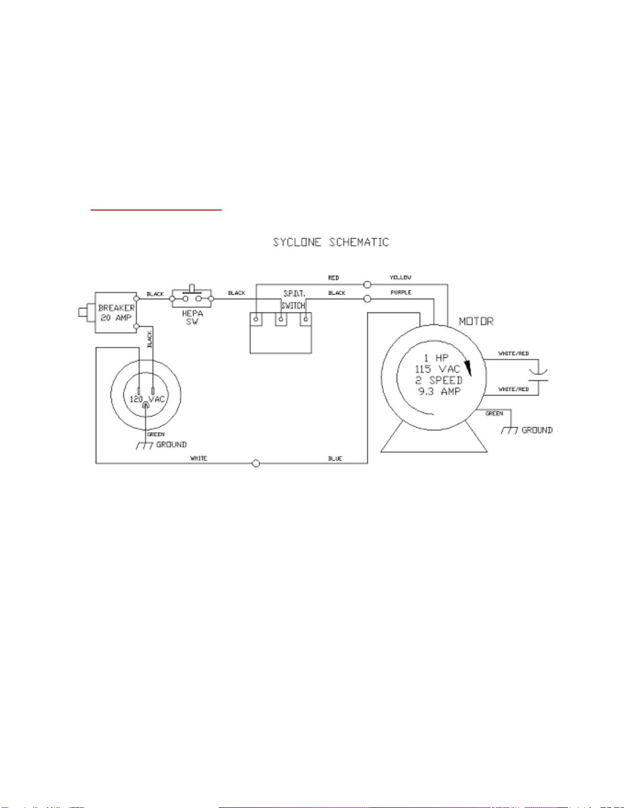
Page 7 of 9 9/19/2012
5.2 Ring Panel Filter Replacement:
5.2.1 Turn the SYCLONE unit off and make sure to disconnect the power supply cord from
the unit.
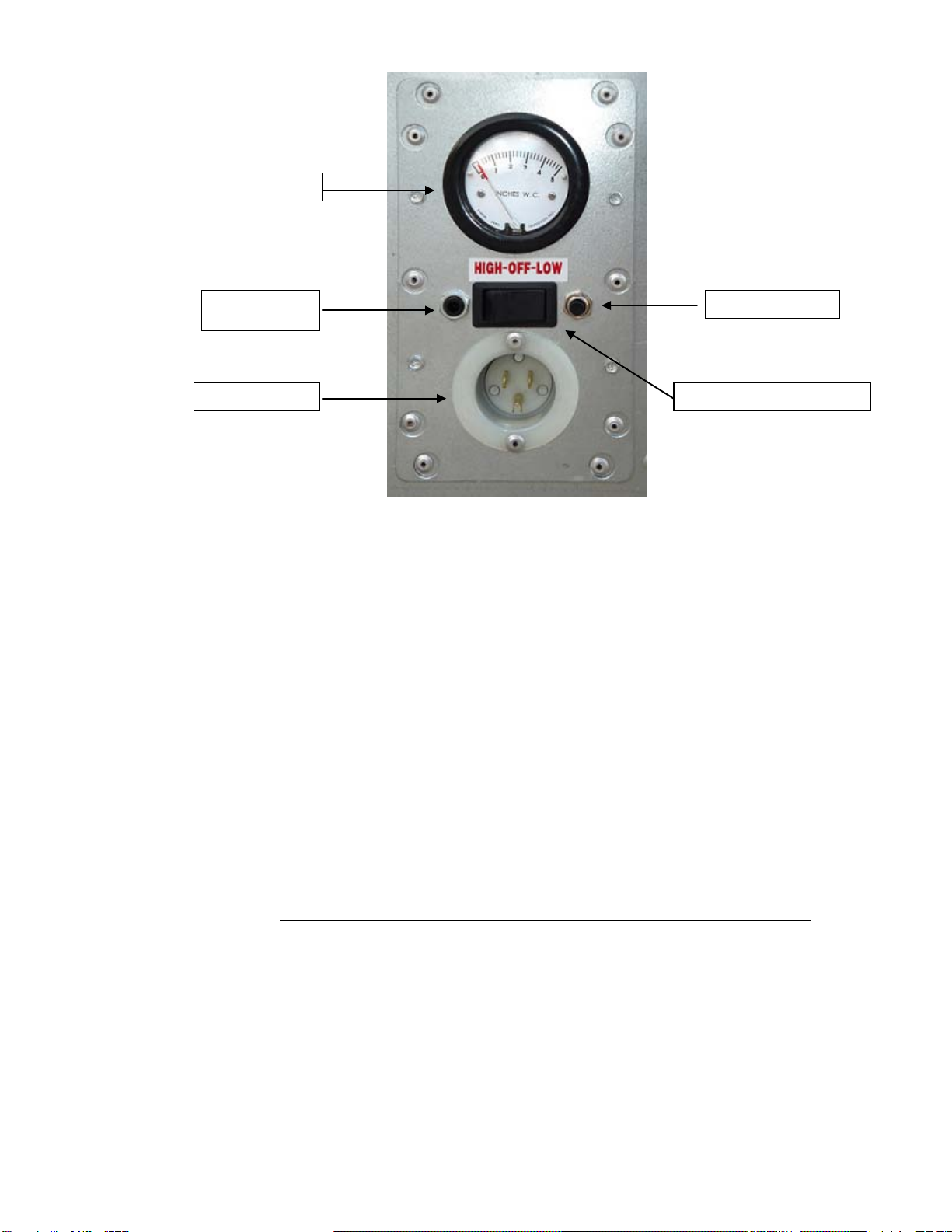
5.2.2 Open the door and remove the contaminated ring panel filter.
5.2.3 Fold in the sides of the contaminated filter and dispose of as per section 5.4.
5.2.4 Install a new ring panel filter making sure to place it against the HEPA filter. This will
position the filter properly.
5.2.5 Close door and fasten the draw latch.
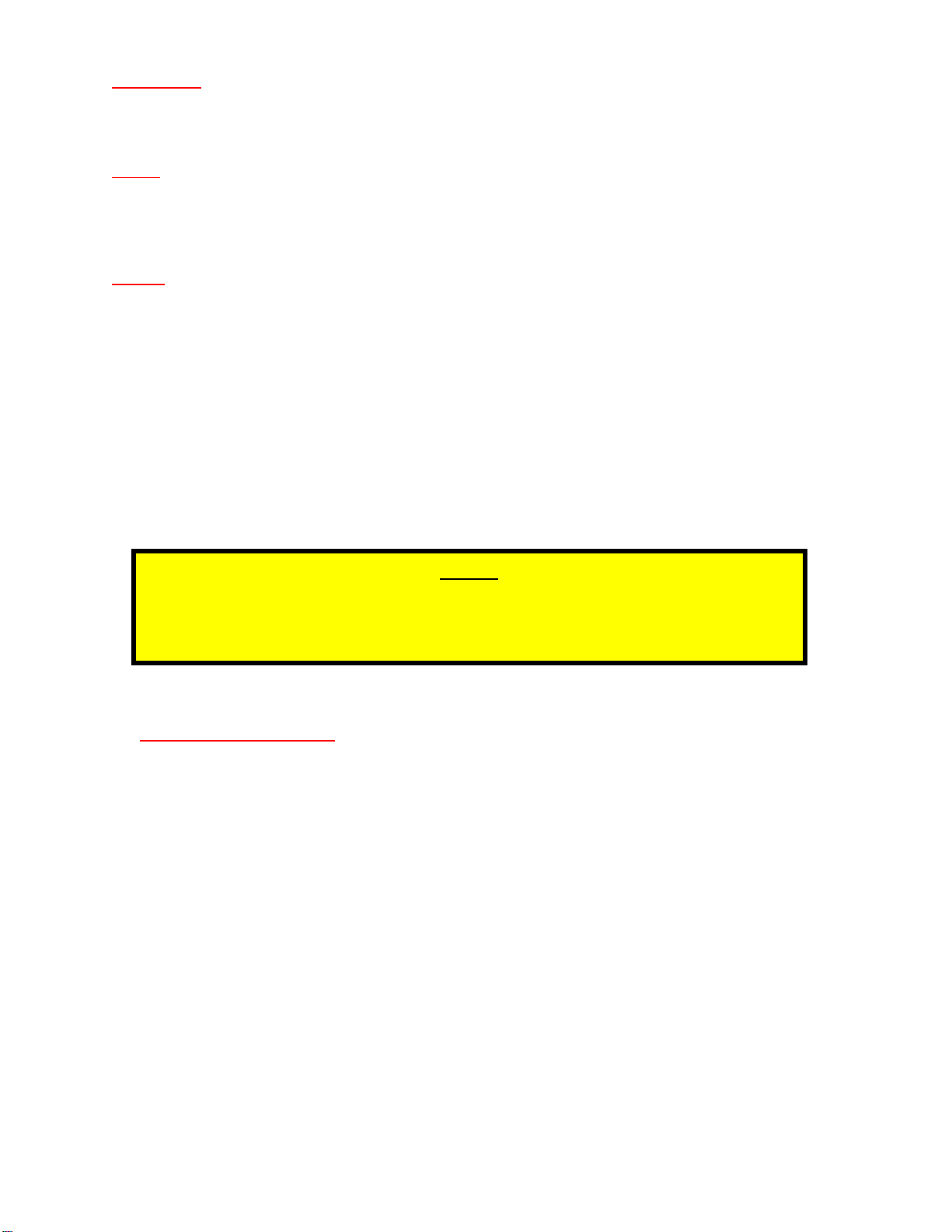
5.2.6 Reconnect the power supply cord, then turn the unit on, and check the pressure
gauge at the control panel.
5.2.7 If the pressure still exceeds the pressure stated above, the HEPA filter also needs to
be replaced.
5.3 HEPA Filter Replacement:
5.3.1 Turn the SYCLONE off and make sure to disconnect the power supply cord from the
unit.
5.3.2 Open the door and remove the ring panel filters, as described in section 5.2.
5.3.3 Remove the HEPA filter by loosening the four nuts and rotating the tabs to the open
position.
5.3.4 Pull the HEPA filter out of the cabinet and dispose of as per section 5.4.
5.3.5 Inspect the gasket on the new HEPA filter housing before installation, to make sure
there are no gaps, cracks, or defects. Any defects in the gasket will allow leakage of
contaminated air through the unit.
5.3.6 Place the new HEPA filter in the unit with the gasket end facing the fan. Check to see
that the filter lies squarely on the base bracket.
5.3.7 Push the HEPA filter against the HEPA flange bulkhead and rotate the looking tabs
to the closed position.
5.3.8 Tighten the HEPA filter hold-down nuts securely to prevent air leaks.
5.3.9 Install ring panel filter as described in section 5.2.
5.3.10 Close door and fasten the draw latch.
ATTENTION
-THE NEW HEPA FILTER NEEDS TO BE THE SAME SIZE AND TYPE, AS THE ONE BEING
REPLACED.
- WHEN THE HEPA FILTER IS REPLACED, THE PRE-FILTER PAD AND RING PANEL FILTER
SHOULD ALSO BE REPLACED. THIS WILL HELP TO EXTEND THE LIFE OF THE HEPA FILTER

Page 8 of 9 9/19/2012
5.3.11 Reconnect the power supply cord, then turn the unit on, and check the pressure
gauge at the control panel. If pressure still exceeds the pressure stated above,
consult your distributor.
5.4 Used filter disposal:
5.4.1 Used filters are considered contaminated waste and are to be disposed in
compliance with all applicable regulations. Personnel replacing filters must wear
personal protective equipment and follow safe work practices as per applicable
regulations.
6. ELECTRICAL SCHEMATIC:

Page 9 of 9 9/19/2012
7. REPLACEMENT PARTS LIST:
Item:
Part Number:
Descriptions:
1
76012803
Motor 1 HP w/ Capacitor
2
76252002
Blower Assembly w/o Blower Stands
3
32001021
SYCLONE Blower Stand Left
4
32001022
SYCLONE Blower Stand Right
5
32001004
SYCLONE Motor & Blower Assembly (Item’s 1, 2, 3 & 4)
6
72650111
Capacitor 25UF, 370V, 50/60Hz
7
Call Dist.
HEPA Filter 24” x 24” x 11.5”
8
Call Dist.
Ring Panel Filter 24” x 24” x 1”
9
Call Dist.
Pre-filter Pad 24” x 24” x 1”
10
32000106
Hepa 1-Clip Kit w/ Hdwr
11
32001008
SYCLONE Control Box Housing
12 32001003 SYCLONE Control Panel Assy. (Item’s 13, 14, 15, 16, 17 & ect.)
13
32001007
SYCLONE Control Panel Plate
14
66020101
Miniature Differential Pressure Gauge 0-5” WC
15 72150202 Breaker - 20 Amp Push Button
16 72270304 Switch Blk. SPDT 3 Prong 2P 120V 20 Amp
17
72250301
PS Receptacle – Recessed Male 15 Amp
18
32001006
SYCLONE Door
19
32001012
SYCLONE Door Guides (1pr)
20
32001018
SYCLONE Cord Bracket
21
32001017
SYCLONE Exhaust Ring
22
74500104
Caster 4” Swivel
23
74500204
Caster 4” Swivel w/ Brake
24
74090101
Grab Handle w/ Base Plate
Table of contents
Popular Air Cleaner manuals by other brands

Aztech
Aztech MT402 Easy start guide

Pure Enrichment
Pure Enrichment PUREZONE HALO user manual

C+R Automations
C+R Automations LUDES AIR 270 Assembly and operation instructions

Honeywell
Honeywell HPA020 Series user manual

Medify Air
Medify Air MA-35 user manual

CFM
CFM CX1000 Installation & maintenance instructions