© 2009 SymCom, Inc. All Rights Reserved 8
TROUBLESHOOTING
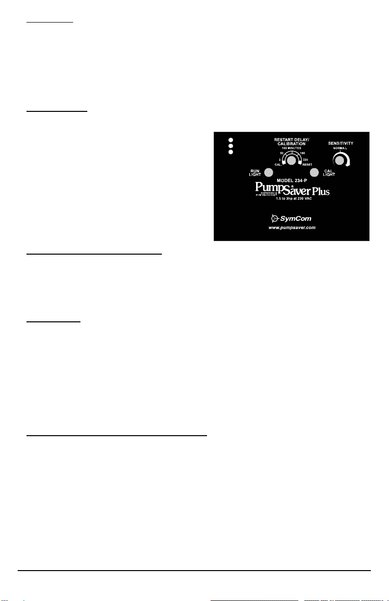
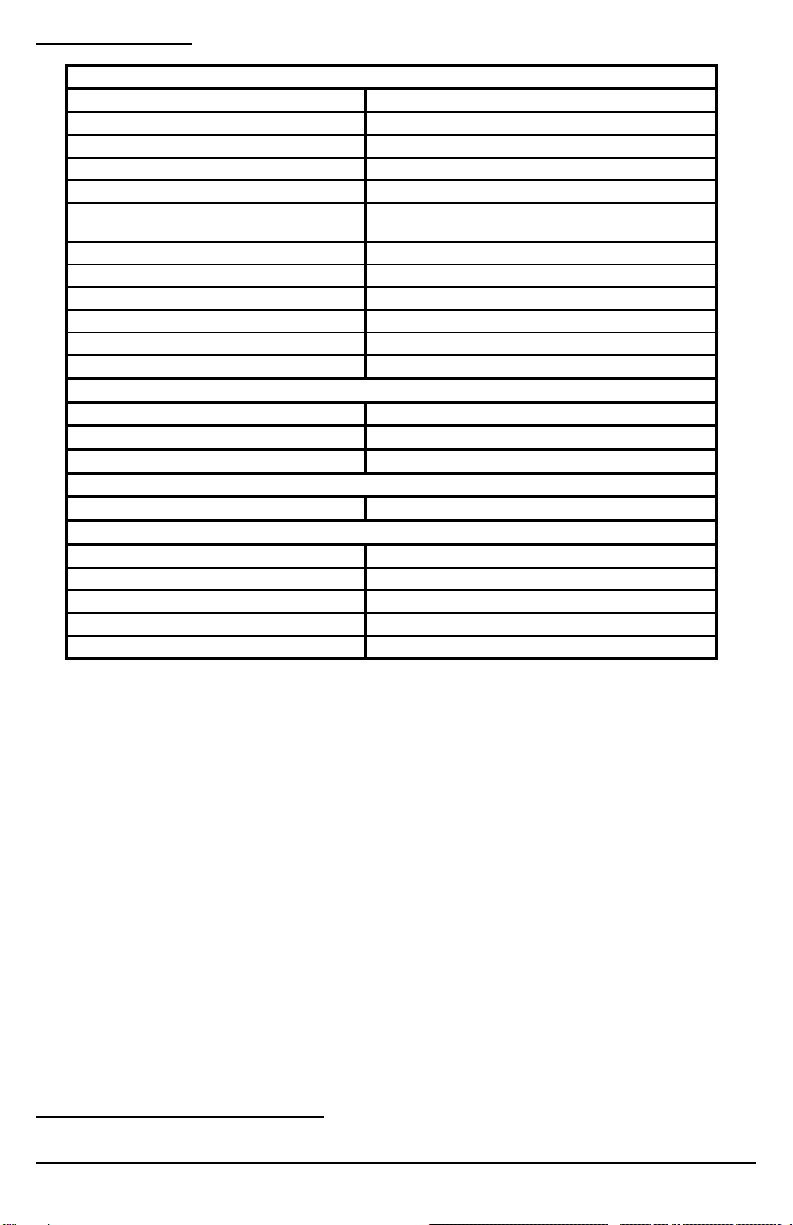
RUN
LIGHT CAL
LIGHT PROBLEM or FUNCTION CORRECTIVE ACTION
On Steady Off RUN:
Pump is running—or ready to
run—no problems in operation
If pump is not running, check for
loose wiring and ensure proper
function of pressure or float
switches.
On Steady On Steady CAL: The PumpSaver®Plus is in
the calibration process. None
Off On Steady
CAL COMPLETE:
The PumpSaver®Plus has
calibrated, the RESTART
DELAY/ CALIBRATION knob was
left in the CAL position. Pump is
off.
Pump will restart as soon as the
RESTART DELAY/
CALIBRATION knob is rotated out
of the CAL position.
Off Off
OFF / MANUAL RESTART: The
pump is not running. Either the
PumpSaver®Plus has tripped on
dry-run, dead-head, or
overcurrent while the RESTART
DELAY/ CALIBRATION knob was
in the RESET position or source
power is not present.
If knob is in the RESET position,
rotate out of RESET—If the CAL
light blinks, check for an
overcurrent condition. If the RUN
light blinks, look for a dry-run or
dead-head condition. If no lights
come on, check incoming power
for adequate voltage.
Blinking Off
DRY RUN / DEAD HEAD:
The PumpSaver®Plus has shut
the pump off due to a dry run or
dead head condition. The unit is
timing through the restart delay
and will try to restart.
Check for restricted flow or
inadequate supply of liquid.
Off Blinking
OVERCURRENT:
The PumpSaver®Plus has shut
the pump off due to an
overcurrent condition. The unit is
timing through the restart delay
and will try to restart if line
voltage is at an acceptable level.
Check for low or high voltage or
jammed pump impellers. If these
conditions do not exist, recalibrate
the unit while it is drawing higher
current (amps should not exceed
SFA).
Blinking
alternately
with the
CAL Light
Blinking
alternately
with the
RUN Light
VOLTAGE FAULT:
The PumpSaver®Plus is
preventing the pump from starting
due to voltage problems. The
voltage is being interrogated and
the unit will remain in this mode
until the voltage is at an
acceptable level.
If the unit remains in this state for
more than 5 seconds, check for
high or low voltage.
Blinking in
unison
with the
CAL.
LIGHT
Blinking in
unison with
the RUN
LIGHT
RAPID CYCLE:
The PumpSaver®Plus has shut
down on rapid cycling. Power
must be removed and reapplied
to reset the unit.
Check for a broken bladder in the
pressure tank (if used), or check
for a defective pressure or float
switch.