manuals.online logo
Brands
  1. Home
  2. •
  3. Brands
  4. •
  5. SymCom
  6. •
  7. Measuring Instrument
  8. •
  9. SymCom MotorSaver 201-SP User manual

SymCom MotorSaver 201-SP User manual

2880 North Plaza Drive • Rapid City, SD 57702
(800) 843-8848 • (605) 348-5580 • FAX (605) 348-5685
www.symcominc.com • email: [email protected]
Features
Bicolor LED indicator
light is green in normal
conditions and red dur-
ing trip conditions.
Compact design saves
precious panel space.
Microcontroller-based
provides better accuracy
and higher reliability
than analog designs.
Transient protected to
meet IEEE 587 and
IEC 1000-4-5 standards
and stand up under
tougher conditions.
10A @ 240 VAC
General Purpose Relay
can switch most loads.
Model 201-SP
Model 201-SP-T
Model 201-SP-T01
Single Phase
Voltage Monitor
•
Engineered
Protection
•
Microcontroller
Based
Protects single phase
systems from:
•Low Voltage
•High Voltage (Option 9)
Additional Features:
•UL and cUL listed
•5 year Warranty
•Made in USA
•Din Rail or
Surface Mount
Model 201-SP is a plug-in voltage monitor designed to protect single phase
motors regardless of size. It can be used on 95-120 VAC (201-100-SP),
190-240 VAC (201-200-SP), or 380-480 VAC (201-400-SP) motors to pre-
vent damage caused by low voltage or high voltage (optional).
The unique microcontroller-based voltage and phase sensing circuit
constantly monitors the voltage to detect harmful power line conditions.
When a harmful condition is detected, the MotorSaver's output relay is
deactivated after a specified trip delay. The output relay reactivates after
power line conditions return to an acceptable level for a specified amount
of time (RESTART DELAY). The trip delay prevents nuisance tripping due
to rapidly fluctuating power line conditions.
9/02
2880 North Plaza Drive •Rapid City, SD 57702
(800) 843-8848 •(605) 348-5580 •FAX (605) 348-5685
www.symcominc.com •email: [email protected]
Specifications
Line Voltage Ranges ................................95 to 120 (100V Model)
....................................................................190 to 240 (200V Model)
....................................................................380 to 480 (400V Model)
Frequency ................................................50 or 60 Hz
Low Voltage (% of set point)
•Trip ............................................................90%
•Reset ........................................................93%
Trip Delay Time
•Low Voltage or Optional High Voltage ......4 seconds
Restart Delay Time
•After a Fault ..............................................2 seconds
•After a Complete Power Loss ..................2 seconds
Output Contact Rating (Pilot Duty)
•SPDT ........................................................480 VA @ 240 VAC
or 10A @240 VAC Gen. Purpose
Transient Protection (Internal) ................IEC 1000-4-5; 1995 to ±4kV
Power Consumption ................................5 Watts (Max.)
Weight ......................................................9 oz.
Socket Available ......................................The same 600V socket can be
Model Number OT08 surface mounted or installed on
(UL Rating 600V) Din Rail
Specifications
•
Operating Points
•
Special Options
9/02
SymCom warrants its microcontroller-based products against defects in material or workmanship for a period of
five (5) years from the date of manufacture. All other products manufactured by SymCom shall be warranted
against defects in material and workmanship for a period of two (2) years from the date of manufacture.
For complete information on warranty, liability, terms, returns, and cancellations, please refer to the SymCom
Terms and Conditions of Sale document.
Model 201-SP
Model 201-SP-T
Model 201-SP-T01
Single Phase
Voltage Monitor
2880 North Plaza Drive, Rapid City, SD 57702 • (800) 843-8848
INSTALLATION INSTRUCTIONS FOR SYMCOM’S
MOTORSAVER®MODELS 201-SP, 201-SP-T, 201-SP-T01
BE SURE POWER IS DISCONNECTED PRIOR TO INSTALLATION!!
FOLLOW NATIONAL, STATE AND LOCAL CODES!
SETTINGS
1. LINE VOLTAGE ADJUSTMENT: Rotate the LINE VOLTAGE ADJUSTMENT to the nominal line voltage feeding the motor to be protected.
POWER-UP
Turn on the power to the motor. The MotorSaver then goes through it's restart delay and the LED will flash green. After the RESTART DELAY, the
MotorSaver ®will energize its output contacts and the RUN LIGHT will turn solid green. If the contacts do not energize and the RUN LIGHT does not
turn solid green, then see the TROUBLESHOOTING section.
Congratulations!!! You have just installed the finest motor protection available!
TROUBLESHOOTING
If the output relay does not energize and the RUN LIGHT does not turn solid green after waiting for the RESTART DELAY time, then:
1. Measure the line-to-line voltage. If the voltage is 10% above (for units with optional high voltage protection) or 10% below the voltage adjust set point,
the MotorSaver is functioning properly, saving your motor from abnormal power conditions.
2. If the unit seems to be malfunctioning, then contact SymCom at 1-800-843-8848 OR 1-605-348-5580 and we will be happy to help you.
To control a motor: Connect the normally open contact in series with the magnetic coil of the motor starter as shown for each model.
Figure No. 1:Typical Wiring Diagram
CONNECTIONS
1. Mount the MotorSaver in a convenient location in or near the motor control panel. If the location is wet or dusty, then the MotorSaver
should be mounted in a NEMA 4 or 12 enclosure.
2. Connect the lines of the power supply to L1 and L2 on the MotorSaver’s octal socket (see Figure No. 1).
3. Connect the output relay to the circuitry to be controlled (see Figure No. 1).
For motor control, use the ‘C’ and the ‘NO’ terminals.
For alarm circuits, use the ‘C’ and the ‘NC’ terminals.
RUN
RESTART DELAY
HIGH / LOW VOLTAGE
GREEN
GREEN
RED
INDICATOR LIGHT
DIAGNOSTICS
WARRANTY
Seller warrants to the buyer that products furnished will be free from defects in material and workmanship, exclusive of corrosion, for a period
of five years from the date of shipment from its factory, provided said products have been installed, maintained and operated in conformance
with any applicable specifications and recommendations of the Seller. The sellers liability under this warranty shall be limited to the
replacement within the aforesaid time of any defective work or material limited at the Seller’s factory and shall not be liable for any labor or
other repair costs made outside the Seller’s factory without the written consent of the Seller. The Seller shall be liable for no other damages
or losses. The warranty described in this paragraph shall be IN LIEU OF ANY OTHER WARRANTY EXPRESSED OR IMPLIED INCLUDING
BUT NOT LIMITED TO ANY IMPLIED WARRANTY OF MERCHANTABILITY OR FITNESS FOR A PARTICULAR PURPOSE.
BOTTOM
2.375"
(60.331)
1.75"
(44.545)
TOP
SIDE
3.15"
(80.010)
.5"
(12.700)
P/N-201-SP
190/240 VAC
www.symcominc.com
LINE VOLTAGE ADJUST
190
200
208 220
230
240
RUN LIGHT
(VAC)
SPECIFICATIONS MODELS 201-SP, 201-SP-T, 201-SP-T01
Line Voltage Ranges 95 - 120 (100V Model)
190 - 240 (200V Model)
380 - 480 (400V Model)
Frequency 50 - 60 Hz
Operating Points
Low Voltage
Trip (% of set point) 90%
Reset (% of set point) 93%
High Voltage
Trip (% of set point)
N/A (Standard)
(110%, Option No. 9)
Reset (% of set point)
N/A (Standard)
(107%, Option No. 9)
Trip Delay Time (Nominal)
Low Voltage 4 Seconds
High Voltage
N/A (Standard)
(4 Seconds, Option No. 9)
Restart Delay Time
After a Fault 2 Seconds
From complete power loss 2 Seconds
Output Contact Rating (SPDT)
Pilot Duty 480 VA @ 240 VAC
General Purpose 10 A @ 240 VAC
Internal Transient Protection Using IEC 1000-4-5:1995 4kv
Power Consumption 5 Watts (Max.)
Weight 9 oz.
DIMENSIONS FOR MODEL 201-SP, 201-SP-T, 201-SP-T01

This manual suits for next models

2

Other SymCom Measuring Instrument manuals

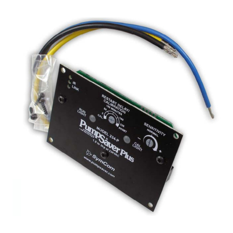
SymCom PumpSaver Plus 234-P User manual

SymCom

SymCom PumpSaver Plus 234-P User manual

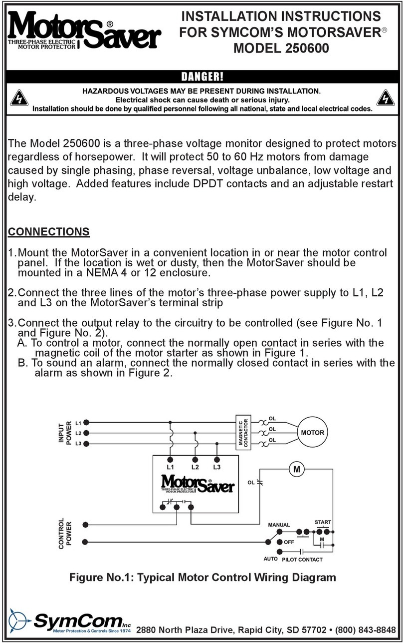
SymCom MotorSaver 250600 User manual

SymCom

SymCom MotorSaver 250600 User manual

SymCom MOTORSAVER 460 User manual

SymCom

SymCom MOTORSAVER 460 User manual

SymCom Motor Saver 460-SP User manual

SymCom

SymCom Motor Saver 460-SP User manual

SymCom MotorSaver 250A Quick start guide

SymCom

SymCom MotorSaver 250A Quick start guide

Popular Measuring Instrument manuals by other brands

Ditel BETA-D instruction manual

Ditel

Ditel BETA-D instruction manual

Omega FMA 4000 user guide

Omega

Omega FMA 4000 user guide

Simex SPP-94 user manual

Simex

Simex SPP-94 user manual

Eaton Cutler-Hammer Instruction leaflet

Eaton

Eaton Cutler-Hammer Instruction leaflet

Hitachi C41V instruction manual

Hitachi

Hitachi C41V instruction manual

Endress+Hauser Analytik Jena Biometra TS1 ThermoShaker Short manual

Endress+Hauser

Endress+Hauser Analytik Jena Biometra TS1 ThermoShaker Short manual

GW Instek LCR-8101 user manual

GW Instek

GW Instek LCR-8101 user manual

axing TZU 22-01 Operation instructions

axing

axing TZU 22-01 Operation instructions

Siargo MF5900 Series manual

Siargo

Siargo MF5900 Series manual

Teledyne Princeton Instruments FER785-MM user manual

Teledyne

Teledyne Princeton Instruments FER785-MM user manual

Schaller humimeter SG1 operating manual

Schaller

Schaller humimeter SG1 operating manual

Tektronix 1340 manual

Tektronix

Tektronix 1340 manual

T&D log-EZ user manual

T&D

T&D log-EZ user manual

Apera Instruments TN400 instruction manual

Apera Instruments

Apera Instruments TN400 instruction manual

AEG NET-STICK Quick setup guide

AEG

AEG NET-STICK Quick setup guide

horiba F-73 instruction manual

horiba

horiba F-73 instruction manual

RD Instruments WorkHorse Sentinel user guide

RD Instruments

RD Instruments WorkHorse Sentinel user guide

DURA Dura-Meter Operator's guide

DURA

DURA Dura-Meter Operator's guide

manuals.online logo
manuals.online logoBrands
  • About & Mission
  • Contact us
  • Privacy Policy
  • Terms and Conditions

Copyright 2025 Manuals.Online. All Rights Reserved.