Synergy SY-BRUW-CWS User manual

SYNERGY UW CUTTING /WELDING SAFETY ISOLATION SWITCH
# SY-BRUW-CWS
PRODUCT CERTIFICATE
EC Attestation of Conformity
In Compliance with following
Directives:
Machinery Directive
2006/42/EC
Low Voltage Directive
2014/35/EU
Pressure Equipment Directive
2014/68/EU

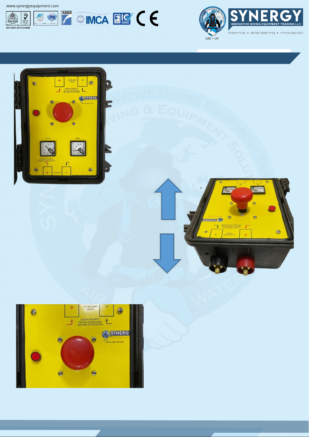
Synergy Safety Isolation Switch for underwater cutting / welding
IMCA D037
IMCA D023
IMCA D018
DESIGN for Surface Oriented (Mix Gas) Diving Systems
Design for surface oriented (air) diving systems
Code of practice for the initial and periodic examination, testing
and certification of diving plant and equipment
Operating Instructions
Description
Ensure the unit is situated in a location so the supervisor or welding co-ordinator can operate
the switch easily.
It is important that the welding cables coming from the welding power source are connected
to the Isolation Switch so that the '+' and '-' terminals match.
If you are using a power source fitted with a polarity switch, still make sure the welding cables
match like-for-like and set the switch on the power-source to negative (-Ve).
NOTE 1:
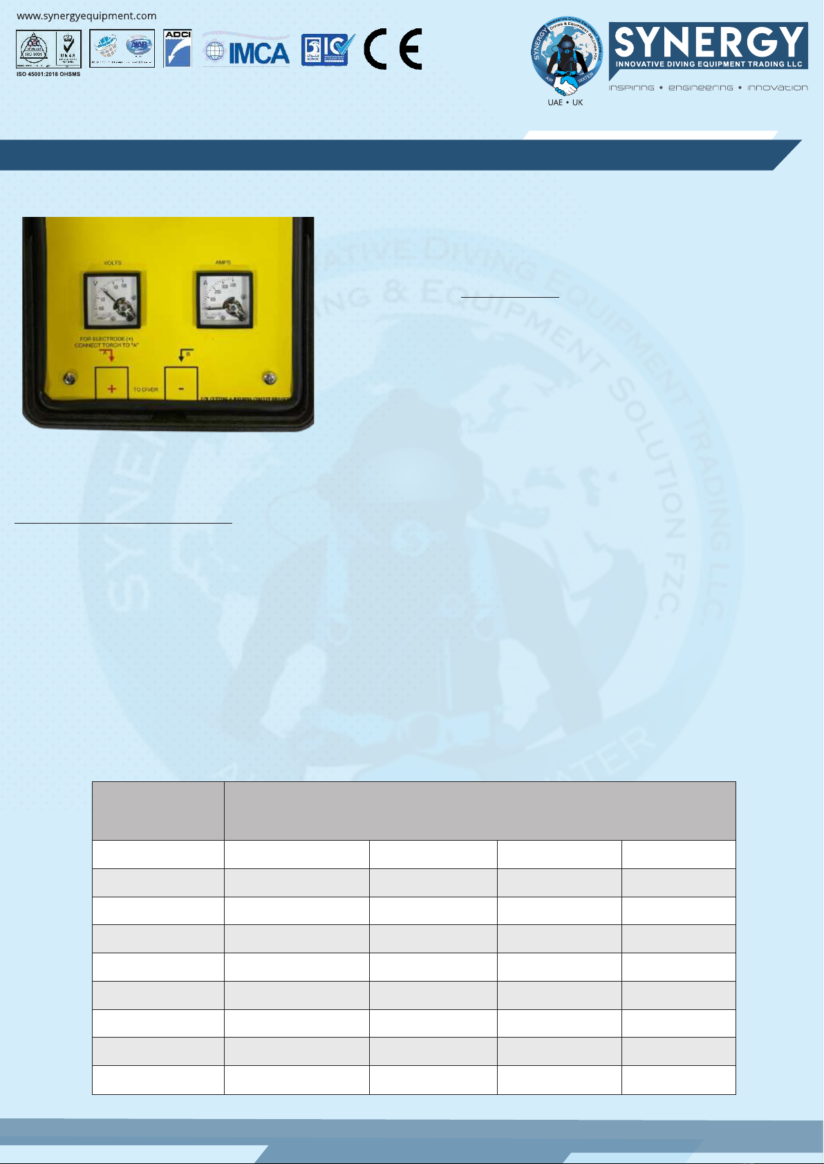
The panel, (top left side) indicates by use of the symbols 'A' and 'B' which polarity may be selected.
The desired polarity will depend on whether the welding stinger cable or the return (earth)
cable is connected to either 'A' or 'B' terminals.
The terminal connections fitted to each Firefly unit are standard DIN (35-50mm2) plugs/socket
(see duty cycle table for ratings).
Ensure you only use approved standard DIN cable connections.
Ensure you connect cables from the welding power-source to the correct side on the Firefly unit.
These should be connected to the panel plug side, as marked on the panel – TO WELDING PLANT.
Ensure you connect like-for-like, matching the polarity symbols to the welding power-source.
Once the cables from the welding power-source are connected, turn on the machine and check to
see that the volt meter registers (no need to connect the welding cables to the diver yet).
The volt meter is a zero centred meter and so the needle should rise in an upwards direction.
If the meter falls (drops) in a downward direction, then the cables are not matched like-for-like!
(Check connections and/or polarity switch and re-test).
NOTE 2:
When using the on/off knob, do not use excessive force, particularly when making COLD, as the
switch will operate with the minimum of resistance.
Connect the cables to the power-source and ensure the machine is 'on'.
Test whether the indicator light operates correctly, pull the red on/off knob to make a live (HOT)
connection; the indicator lamp will now illuminate.
By pushing the red on/off knob down (making is COLD) the indicator light will extinguish.
This procedure now ensures the correct set-up and you are ready to connect the welding cables
to the diver.
Should the lamp fail to illuminate, then the bulb may have blown. (Please return your unit for inspection).
Sr.
1
2
3
Polarity changes may then be set on the Isolation switch as set out below.
4
5
6
7
8
9
10
11
12
13
14
15
All Isolation switch units are also fitted with an indicator lamp.
16
17
18
19
20
SYNERGY UW CUTTING /WELDING SAFETY ISOLATION SWITCH # SY-BRUW-CWS

SYNERGY UW CUTTING /WELDING SAFETY ISOLATION SWITCH # SY-BRUW-CWS
Once the cables from the welding power-source are
connected, turn on the machine and check to see
that the volt meter registers (no need to connect the
welding cables to the diver yet). The volt meter is a
zero centred meter and so the needle should rise in
an upwards direction. If the meter falls (drops) in a
downward direction, then the cables are not
matched like-for-like! (Check connections and/or
polarity switch and re-test).
All Isolation switch units are fitted with a large,
red bulbous on/off knob. To operate, ,simply
pull in a vertical direction to make it HOT and
push down to make it COLD.
NOTE 2: When using the on/off knob, do not use
excessive force, particularly when making COLD,
as the switch will operate with the minimum of
resistance.
All Isolation switch units are also fitted with an indicator lamp.
Connect the cables to the power-source and
ensure the machine is 'on'. Test whether the
indicator light operates correctly, pull the red
on/off knob to make a live (HOT) connection; the
indicator lamp will now illuminate. By pushing the
red on/off knob down (making is COLD) the
indicator light will extinguish. This procedure now
ensures the correct set-up and you are ready to
connect the welding cables to the diver. Should
the lamp fail to illuminate, then the bulb may have
blown. (Please return your unit for inspection).

SYNERGY UW CUTTING /WELDING SAFETY ISOLATION SWITCH # SY-BRUW-CWS
Now you are ready to connect the welding cables to the
diver side on the Firefly unit. You will note that on this side
of the panel as well as the usual +/- polarity symbols, you
will also see instructions on how to change polarity. All
polarity changes MUST ONLY be made from the diver side
of the panel. To deliver positive (+Ve) polarity to the stinger
(electrode holder) connect the stinger cable to the terminal
marked [A]. To deliver negative (-Ve) polarity to the stinger
cable, connect the stinger cable to the terminal marked [B].
DO NOT ALTER THE CABLES FROM THE WELDING MACHINE
SIDE OF THE PANEL, OR CHANGE THE CABLES ON THE
WELDING MACHINE.
The Synergy Safety isolation switch is fitted with an approved 400-amp, dual pole switch; the duty
cycle of which is as shown on the data label, affixed to the panel (see copy below). As the switch is
fitted in an enclosed space, the duty cycles are adhered too, otherwise serious overheating may
occur. If you notice the unit getting hot during operational use, then allow an extended cooling
period to take place.
It is important to ensure you use the correct sire of welding cable for the selected current.
However, please note voltage drop may also need to be taken into account, as the size and length
of the welding cable used may also need to be considered. Typical current ratings data for use with
copper welding cables manufactured in accordance with BSEN 50525-2-81:2011 are shown below.
Additional Technical Data:
Nominal Area
2
mm
16
25
35
50
70
95
120
150
Current ratings measured in Ampere for copper conductors
for a single cycle maximum duty cycle per-cent
100%
135
180
225
285
355
430
500
580
85%
145
195
245
305
385
470
540
630
60%
175
230
290
365
460
560
650
750
35%
230
300
375
480
600
730
850
980

SYNERGY UW CUTTING /WELDING SAFETY ISOLATION SWITCH # SY-BRUW-CWS
Synergy Safety Isolation Switch units are not fully waterproof, but are rated IP67 with the lid closed*(see
details below).
*IP (or “Ingress Protection”) ratings are defined in BSEN 60529:1992+A2:2013. They are used to define levels
of sealing effectiveness of electrical enclosures against intrusion of foreign bodies (tools, dirt) and moisture,
etc. The numbers have a specific meaning. The first digit indicates the degree of protection (for people)
from moving parts, as well as the protection of enclosed equipment from foreign bodies. The second digit
defines the protection level that the enclosure enjoys from various forms of moisture (drips, sprays,
submersion etc).
All Isolation switch units use the highest quality, UK manufactured components and we offer a 6
month warranty against any defective parts. The Isolation switch has undergone independent
testing by Albright International to validate thermal profiling performance (duty cycle) ratings and
the switch is approved by UL and has US and Canadian approvals.
Online certification details may be obtained against file #E181430 on the www.ul.com website. The
links to the following file numbers; NRNT2.E181430 and NRNT8.E181430.
NOTE: Access to the UL site has changed, you will now have to register to utilize this website,
although this can be done free of charge
All Synergy Safety Isolation switch units are CE marked and a declaration of conformity certificate is
available upon request.
IP Rated Enclosure chart
First Digit (intrusion protection)
0
1
2
3
4
5
6
Second Digit (moisture protection)
0
1
2
3
4
5
6
7
8
No special protection
Protection from a large part of the body such as a hand (but no protection from deliberate access); from
solid objects greater than 50mm in diameter
Protection against fingers or other object not greater than 80mm in length and 12mm in diameter.
Protection from entry by tools, wires etc, with a diameter of 2.5mm or more.
Protection against solid bodies larger than 1mm (eg. fine tools/small etc).
Protection against dust that may harm equipment.
Totally dust tight.
No protection
Protection against condensation.
Protection against water droplets deflected up to 15" from vertical
Protected against spray up to 60" from vertical.
Protection against water spray from all directions.
Protection against low pressure water jets (all directions)
Protection against string water jets and waves.
Protected against temporary immersion.
Protected against prolonged effects of immersion under pressure.

SYNERGY UW CUTTING /WELDING SAFETY ISOLATION SWITCH # SY-BRUW-CWS
The chart shown below provides details of the thermal testing undertaken by Albright . The graph show
details of the temperature gradients involved during testing. The unit was subjected to a continuous 135
minutes testing period at 250 amps DC and shows the moving contact stabilized at 152.8 degrees C. The
voltage drop across the unit was 397mV and the switch performed satisfactorily during the test.
Enclosure are available in three models; large and small steel and a utility case.
Material: Steel HPX resin
Type: Portable
Body Colour: Olive
Wall Thickness: 1.2mm
IP Rating: IP67
Supplementary Information:
Details with regards to the safe use of electricity underwater may be obtained from the code of practice D045,
published by IMCA. It is highly recommended that all persons involved with using electricity underwater be familiar
with this document.

SYNERGY INFRASTRUCTURE

P.O. Box – 237849, Warehouse No 8,
Al Maidoor Warehouse, Al Qusais,
Industrial Area - Dubai - UAE
Tel
Fax
UAE
UK
Website
Email
For Sale
Contact us
009714 2580533
009714 2580534
00971505648178
00447951966260
:
:
:
:
www.synergyequipment.com
:
:
:
SYNERGY UW CUTTING /WELDING SAFETY ISOLATION SWITCH
# SY-BRUW-CWS
PRODUCT CERTIFICATE
EC Attestation of Conformity
In Compliance with following
Directives:
Machinery Directive
2006/42/EC
Low Voltage Directive
2014/35/EU
Pressure Equipment Directive
2014/68/EU
Table of contents