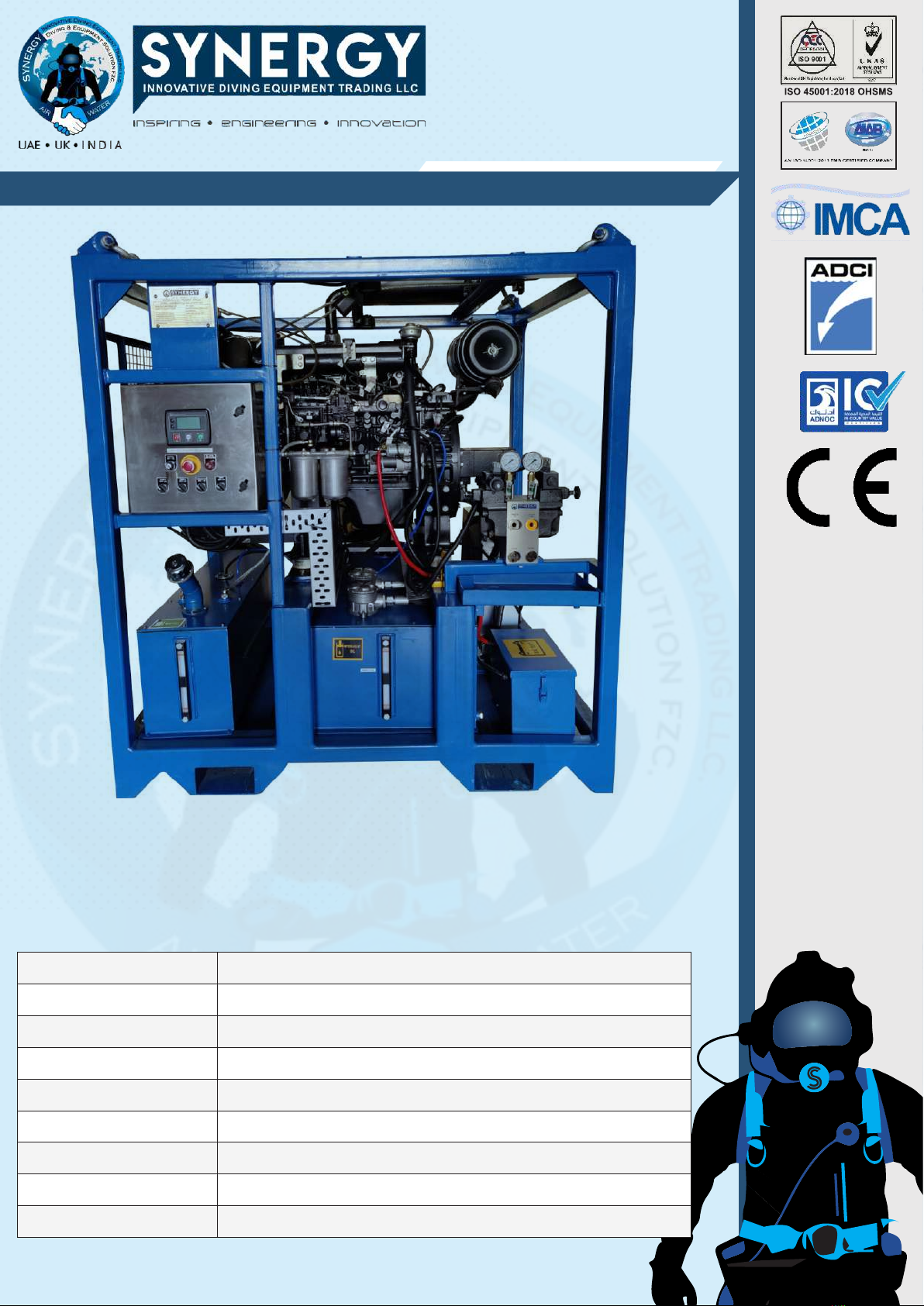
SYNERGY DIESEL ENGINE DRIVEN HYDRAULIC POWER PACK
Operation
The DHPU is a simple unit that provides pressure and flow for an open center hydraulic Tools. Closed center valves have the
pressure port blocked in the neutral position. Heat builds up in the system quickly as the full flow of the system is dumped
over the system relief since the flow cannot return to tank through the valve.
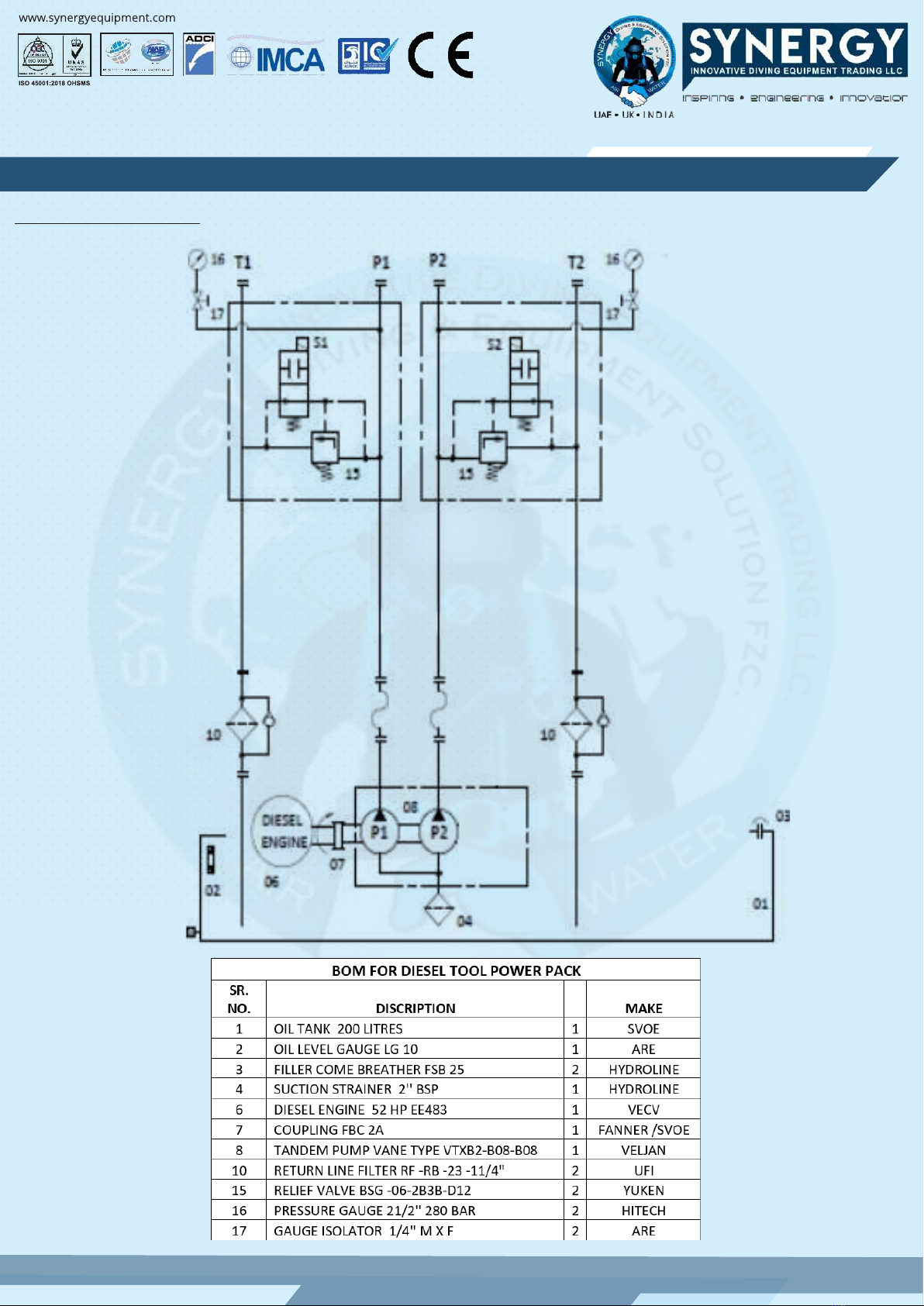
The prime mover for the hydraulic pump is the diesel engine. The engine rotates the pump shaft at the speed selected and
the torque output is dictated by the load on the pump. This model has two fixed displacement Vane pumps coupled to the
engine. The Vane pump has two sections and provides hydraulic power to either 1 or 2 the open centered circuit hydraulic
tools .
The following sequences assume the necessary installation steps have been completed, and the unit is ready for start up.
Both pumps ie. Pump1 and 2 are 24.9 cc/rev (the individual pumps @1500RPM will give a flow of 37.4 LPM and
45LPM@1800 approximately
Two Tools mode with flow up to25-45 LPM on each tool.
In this mode connect the pressure line to P#1and P#2 and Return line 1& 2 connection on return line filter respectively.
Once the Engine is started load the power pack by switching on PUMP 1 and PUMP 2 switch as required. Set the pressure of
the relief valve by shutting Off the Pressure line valve or closing the pressure line on both circuits respectively. The relief
valve should be set with the pressure line closed only.
Ideally the engine should operate at 1500 RPM and that will give a flow of 37.4 LPM. The flow can be increased or decreased
by varying the engine RPM.
The flow should be adjusted to optimum flow (limited to Maximum flow) Refer to Tool specifications that is being used but
both pumps flow will be the same. The pressures can be individually set on each pump. Maximum operating pressure for
this mode is 140 Bar /2000 PSI
In this operating mode when only a single pump is being used the pump pressure can be increased to 210 Bar/3000 PSI
Once the Engine is started load the power pack by switching on load valve. Set the pressure of the relief valve by shutting
Off the Pressure line valve or closing the pressure line. The relief valve should be set with the pressure line closed only.
Ideally the engine should operate at 1500 RPM and that will give a flow of 37.4 LPM. The flow can be increased or decreased
by varying the engine RPM.
The flow should be adjusted to optimum flow (limited to Maximum flow ) Refer to TOOL specifications that is being used .
Maximum operating pressure for this mode is 140 Bar/2000 PSI .
DO NOT SET THE RELIEF VALVE HIGHER THAN THE POWER UNIT DESIGN PRESSURE OR THE ALLOWABLE PRESSURE TO
THE COMPONENTS.