Synergy HB-02 Birdroni Installation guide

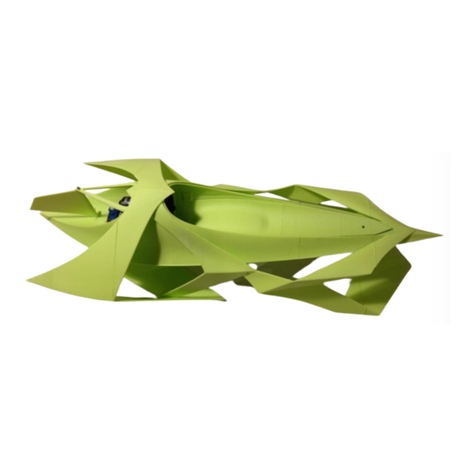
HB 02 Birdroni Assembly Instuction Manual

This instruction manual contains the steps needed in order to assemble the HB–02
Birdroni, including the assembly of 3D printed parts, installation of waterproofing,
and the installation of the electronics. You can refer to the electronics handbook
here.
About
About………………………………………………...........…………………………..
3D printed Parts………………………………………………………………………
Non
-3D Printed Parts ………………………………………………………………..
Before We get Started………………………………………………………………..
Kit Assembly Instructions………………………………...……………………….
Electronics Installation Instructions………………………..…………………….
Page Number
For this kit you will need the 3D printed parts and non 3D printed parts which come
included.
The list of electronics that you will need include: 50mm EDF (without a lip), ESC, LiPo
Battery, Receiver and Transmitter.
You will also need the following common household tools: scissors, tape (Duct Tape or
Masking Tape).
What you will need
1
2
3
4
5-
11
11-
14
1

3D Printed Parts
Part 1: Nose Part 2: Second Hull Piece
Part 3: Third Hull Piece Part 4: Fourth Hull Piece
Part 5: Front Cover
Piece Part 8: Servo Casing Part 9: Rear Hydro
Surface Right Tip
Part 11: Rear hydro surface base
Part 6: Rear Cover
Piece
Part 7: Stopper
Part 10: Rear Hydro
Surface Left Tip
Part 12: Rear hydro surface bottom Part 13: Front Hydro surface base
Part 14: Front hydro surface bottom Part 15: Rudder Part 16: Rudder Mount
Please Note: Your parts may differ slightly from the parts in the images shown, please rest assured that you have the
latest and correct parts.
2

Non-Printed Parts
Included in the kit
Servo Motor Seal Glue and Activator
Wire
Cable Extensions M3 and M1 Bolts
Wax
Electronics: Not Included in the Kit
Please Note: These may differer from your electronics.
LiPo Battery EDF ESC
Transmitter Receiver
Wire, 1mm diameter
3

1. Due to the nature of FFF 3D printing some
warping may have occured on the face on which the
part was printed. This warping is purely cosmetic
and can easily be solved by applying additional glue
and smoothing it out before activating it. This will
ensure the gap due to warping is sealed.
Before we get started:
Safety Notices:
1. Read the glue and activator label ad take care while using it. The glue sets very
quickly and will stick to your skin if you’re not careful
2. Take care when handling the 3D printed parts as some contain very sharp
edges
Repeated techniques:
Bonding parts using Glue and Activator Guide:
1. Ensure you test fit the two faces you will be bonding together to ensure you’re
bonding the correct faces in the correct orientation and to get familiar with how
best to hold them as they set
2. Apply glue to one of the two faces you will be bonding together, ensuring it is
evenly spread on the face. Make sure not to apply too much glue so it doesn’t
overspill and cause an external glue line at the joint.
3. Spray activator on the other face (the one without the glue) and wait for it to
evaporate. You can gently blow on it to make it evaporate faster (this only takes a
few seconds).
4. Carefully press the two faces together, ensuring you line them up correctly, and
hold the parts in this positions for around 10 seconds until they set.
5. You may have to spray on more activator on the join if it has not fully set.
6. Please note that some sanding of the joints may be required if excess glue is used.
Recommendations:
1. If you haven’t used glue and activator previously please do practice using some
paper which you draw two identical lines on and glue them together so the lines
are bonded on top of each other. This will give you experience so you know how
fast the glue sets and how much repositioning time you have.
Please be aware that:
2. Some part may differ slightly to the pictures shown in this kit, don’t be alarmed,
you have the latest part. This manual was shot with a prototype model which
received some minor udgrades
4

Kit Assembly Instructions
Step 1
•Prepare parts 3 and 4
•Follow the ‘Using Glue and Acticator Guide’,
here is a short summary:
•Test fit these together prior to gluing to
ensure the correct faces are bonded
together
•Take the glue and apply it to one of the
faces which you will bond together
•Apply the activator to the other side and
press the two parts together, ensuring they
are lined up perfectly
•Hold together for around 10 seconds while
the glue sets
•Ensure sufficient glue used for a sealed hull
Step 2
•Prepare the parts shown: part 2 and
bonded hull piece
•Test fit the faces which are to be bonded
together (notice the orientation in the
picture) and use the glue and activator to
bond them together.
•Ensure you follow the G&A Guide
instructions
Step 3
Step 4
•Prepare the parts shown: part 1 and
bonded hull piece
•Test fit the faces which are to be bonded
together (notice the orientation in the
picture) and use the glue and activator to
bond them together.
•Ensure you follow the G&A instructions
•Prepare the parts shown: parts 5, 6 and
bonded hull piece
•Test fit the faces 1 and 2 and use the glue
and activator to bond them.
•Ensure you follow the G&A instructions
•Your cover is now complete!
•Test fit your cover in the hull, sliding it
below the two ridges at the back
•The main assembly of your hull is now
complete!
12
5

Step 5
•Prepare the EDF and the hull, remove the
lip of the EDF if it has one.
•Test fit the EDF in the hull EDF mount by
inserting it from to front of the hull to the
rear, notice how much clearance there is
between it and the mount walls.
•Take it back out and wrap tape around the
edf; and keep testfitting it until it is a very
snug fit, where force is needed to fit it in
•Once snug fit the EDF in , ENSURING THE
EDF WIRES ARE FACINGS DOWNWARDS
AT THE REAR.
•IT IS VERY IMPORTANT THAT YOUR EDF
IS MOUNTED SECURELY, SO PLEASE DO
DOUBLE CHECK
Step 6
•Prepare parts 7 and the hull with the EDF
mounted
•Place these in the groove closest to the
EDF (see arrow)
•To remove your EDF, if you want to use it in
another RC kit, simply pull this stopper out
from the slot in the part
Step 7
•Prepare the wire extenders
•Attach wire extenders to your bullet
connectors of the EDF
•Wrap tape on top of them to ensure they
do not detach - IMPORTANT
•Insert the extended EDF wires therough
the oval hole in the hull behind the EDF
•The EDF is now mounted!
6

Step 8
Step 9
Step 10
•Prepare the parts shown: part 8 and the
servo motor
•Note the servo motor had screw attachment
points removed for simpler mounting
•Notice the orientation of the servo relative
to part 8
•Insert the servo into part 8 (following the
arrow direction), ensuring that you thread
the servo cables through the hole in the
servo housing
•Push it all the way to the bottom (the servo
will not be flush with the top curved face of
part 8).
•Glue the servo into the servo mount.
•Take the assembled bodyshell of the HB-02
and the servo housing assembly
•Notice the orientation of these parts relative
to each other, and place the servo housing
inside of the rectangular hole at the rear of
the hull
•Notice the flanges where the servo housing
sits on top of place glue on them, push the
servo housing fully down and bond.
•Ensure you follow the G&A Guide
instructions
•Prepare the parts shown: servo mounted in
part 8 and the yellow wax seal
•Take some wax seal and push it into the
hole of the part 8 where the cables are
pertruding from
•Strategically add the wax until this hole is
fully sealed and looks like the picture
shown.
•Prepare the wax and assembled
bodyshell
•Take some of the wax seal and place it all
around the EDF wires, ensuring there are
no gaps where the water could get into
the hull.
Step 11
7

Step 13 •Prepare the parts shown: parts 11 and 12
•Notice the orientation of parts in the picture
•Part 12 has a sligth curve which matches
part 11 perfectly, make sure you have the
correct orientation
•Test fit the faces which are to be bonded
together bond them together.
•Ensure you follow the G&A Guide
instructions
Step 14
•Prepare the parts shown: parts 9, 10 and
the bonded rear hydro surface
•Notice the orientation of parts in the picture
and test fit the faces which are to be
bonded together.
•Begin by bonding part 10 to the left sede of
thre rear hydro surface.
•Once the left side is bonded, take part 9
and bond it to the right side of the rear
hydro surface.
•Ensure you follow the G&A Guide
Step 12
•Prepare the parts shown: part 13 and 14
•Notice the orientation of parts in the picture
and test fit the faces which are to be
bonded together bond them together
•Ensure you follow the G&A Guide
instructions
8

Step 15
Step 16
Step 17
Step 18
•Prepare the parts shown: the hull, front
hydro surface and rear hydro surface
•Take care in the followings steps when
assembling these parts, it is crutial that they
line up withthe bonding points so that the
hydro surfaces are in the correct place
•These hydro surfaces attach to the hull in
multiple parts and the order in which they
are bonded to this parts needs to be
followed so they line up
•Take the hull and the front planing surface
•Notice the orientation of parts in the picture
and test fit the faces which are to be
bonded together
•There are 2 pairs of faces which need to be
bonded together, do this one at a time
•Ensure you follow the G&A Guide
instructions
•Take the hull and the rear planing surface
•Notice the orientation of parts in the picture
and slide the rear hydro surface onto the
hull in the direction of the top arrow (see
photos on the left)
•Brint it forward until the edges highlighted
in red touch.
•The rear surface needs to be bonded in
multiple places this order, please follow the
numbers displayed on the pictures.
•The two touching pairs of faces need to be
bonded together first, do this one at a time
starting with 1, then 2, ensuring you line up
the top corners of the edges
•Once you’ve bonded the first 3 points, turn
the boat upsidedown and glue the rest of
the points, again in chronological order.
•Ensure you follow the G&A Guide
instructions
•The main body is now complete!
1
2
3
4
5
6
9

Step 19
Step 20
Step 21
Step 22
•Prepare the parts shown: part 15 and the
wire
•Cut a piece of wire about 30mm long
using some scissors or wire cutters
•Test fit the wire inside of hinge hole of the
rudder from the underside.
•Pull the wire back out so you can see
around half of it and add some glue to the
wire.
•Insert it into the rudder leaving 5mm
visible and activate the glue
•Prepare the parts shown: part 16 and the
assembled body shell
•Take part 16 and test fit it to the rear of
the EDF mount, lining the attachment
points of the Hull with the rudder mount
as shown.
•Bond the two faces of the rudder onto the
hull at the same time, and pay close
attantion to ensure they are aligned and
centered. Add sufficient ammount of glue.
•Ensure you follow the G&A Guide
instructions
•Take the rudder and insert the wire (which
you installed to the bottom of it) into the
hole behind the servo in the hull
•Prepare an M1 bolt
•Line the rudder up with the rudder mount
(you will have to pull the rudder mount
upwards slightly to fit the rudder
underneath) and install the bolt to hold the
rudder in place
•Test the rudder movement, it should feel
smooth without significant resistance
•Shorten one of your servo arms so it has
4 holes showing, use scissors to cut the
tip off (result shown in pictures)
•Cut a piece of wire which is 50mm long
•Curve the two tips of it as shown in the
picture, this will be your steering arm
•Insert one of the tips into the steering arm
mount on the side of the rudder and the
other into a servo arm.
10

Step 24
Step 25
•Prepare the seal (shown) and the assembled
bodyshell
•Teake the seal and align it around the edges of
the hull openeing, to get familiar about where to
stick it down.
•Now peel the backing of the seal off, in sections
and stick it onto the hull opening, then peel off
more backing and stick down untill the opening
is covered.
•You will have some seal overlap, mark where
this happens and trim it to this length
•Once the seal is stuck down go back and glue it
in more spaces using the glue and activator as
this is more durable than the seal adhesive.
•Prepare the parts shown: Cover, M3 bolt,
assembled bodyshell
•Take the cover and fit it onto the hull, sliding
it under the two cover holders jus in front of
the EDF
•Push the cover back over the rear seal until
the bolt hole and the insert in the hull line up.
•Take the M3 bolt and screw the front of the
cover down, you can do this by hand.
Step 23
•Insert one of the tips into the steering arm
mount on the side of the rudder and the
other into a servo arm. (you may find it
easier to take the servo arm off to do
this))
•Press the wire so it hooks around both
attachment points, this is very imoptant to
stop it from sliding off
11

Step 1
•Get all of the electronics ready, see page 1 for guidance
•If your ESC isn’t waterproof it is recommended to waterproof it
Step 2
•Plug EDF into the ESC
•Place the ESC inside and tuck the
wires underneath the side overhang;
Step 3
•Plug ESC into receiver CH 3, when
plugging 3 pin connectors ensure the
orientation is correct; the lightest
colour, yello usually, shoild be facing
the top face of the receiver as shown
•Plug Servo Motor into receiver,
channel 2 in this case, this may differe
for you
Installing the Electronics
Step 4
•Plug in the battery, the battery shown
has a connector on it to match with
the ECS connector
•Turn on your controller, ensuring it is
paired with your receiver
12

Step 5
•Package the electronics in a similar mannor as
shown
•Ensure your battery is sitting bellow the EDF,
you should slide it under the rear cover seal
until it is up to half under
•This will ensure a good position of the centre
of mass for optimal stability and planing
behaviour
•Please note that the packaging of the
electronics will differ for different electronics,
so the battery place,ent for the optimal centre
of mass may differ too
•Don’t forget to unplug the battery when not
running the HB-02 to prevent the LiPo from
discharging too much, as this will result in the
inability to recharge it
•Test your electronics,
•Servo movement, move the servo control and
see the sservo movement
•Test the EDF by increasing the throttle slightly
and placing your hand behing the EDF
•You should feel air blowing on your hand, if
you dont then place your hand in front of the
EDF intake, take caution
•If you feel the air blowing from the back to the
front then you need to reverse 1 of your EDF
to ESC cables; unplug the battery take unplug
1 cables from the ESC and plug them back in
the opposite way;
•Plug the battery back in and repeat the test;
Step 6
13

Step 7 •Go out and enjoy yourself with your
very own HB-02 Birdroni!
14
Other manuals for HB-02 Birdroni
1
Table of contents
Other Synergy Toy manuals