• All-metal and 2mm carbon fiber construction
• CNC machined 6061-T6 aluminum and Delrin components
• 140mm full head width for optimal disk loading
• Extra wide head block for quick cyclic response and high stability
• Capable of 2800+ RPM head speed for maximum performance
• Machined Delrin helical main drive for quiet, efficient power transfer
• 6mm width belt-driven tail with spring tension system
• 10mm main shaft with triple support bearings
• 8mm head axle with pivot rocker and solid dampers
• 6mm tail shaft with HD tail hub and HD grips
• 24mm self-supporting boom (no boom supports needed)
• Turnbuckle linkages for quick/precise adjustments
• Adjustable C.G. battery tray with quick locking system
Motor: 4020 class with 5mm shaft (1350-1400kV recommended)
ESC: 6S 90A or greater
Main Blades: 500-520mm (516 Rail Blades recommended)
Tail Blades: 80mm (80.6 Rail Blades recommended)
Battery: 6S 3850-4500 mAh
Cyclic Servos: Mini Required
Tail Servo: Full Size (760us tail servo recommended)
Main Ratio: 11.31-8.62:1 (18T included; 10.06:1)
Tail Ratio: 5.0-4.1:1 (20T included; 4.5:1)
Main Rotor Diameter: 1172mm (with Rail 516mm)
Tail Rotor Diameter: 228mm (with Rail 80.6mm)
Congratulations on your purchase of the Synergy 516 radio controlled helicopter kit!
The Synergy 516 was designed and developed by Botos Design & Distribution Inc.. The design of the Synergy 516 emerged from many years of
experience in the hobby including design, research & development, and last but not least as a world class pilot who truly enjoys this wonderful
hobby.
This radio controlled helicopter is NOT A TOY. It is a sophisticated piece of equipment; it was designed and intended for hobby use only. If not
properly assembled, maintained, and operated, it is capable of causing property damage and bodily harm to both the operator and/or spectators.
Botos Design & Distribution Inc., its affiliates, and its authorized distributors assume no liability for damage that could occur from the assembly or
use/misuse of this product. If you are new to the hobby we strongly recommend seeking the help and advice from an experienced modeler.
Operating a model helicopter requires a high degree of diligence and skill. If you are new to the hobby, it is best to seek help and guidance from
experienced radio controlled helicopter pilots. This will both greatly speed up the learning process and make it much safer for you. For those pilots
who will be operating their Synergy 516 in the United States, we strongly recommend joining the AMA. The AMA is a non-profit organization
that provides services to the model aircraft pilots. As an AMA member, you will receive a monthly magazine entitled Model Aviation and most
importantly a liability insurance plan to cover against a possible accident or injury. All AMA charter aircraft clubs require individuals to hold a
current AMA sporting license prior to operation of their models.
For further information, you can contact the AMA at:
Academy of Model Aeronautics
5151 East Memorial Drive
Muncie, IN 47302
(317) 287-1256
Features: Specifications:
01 | INTRODUCTION
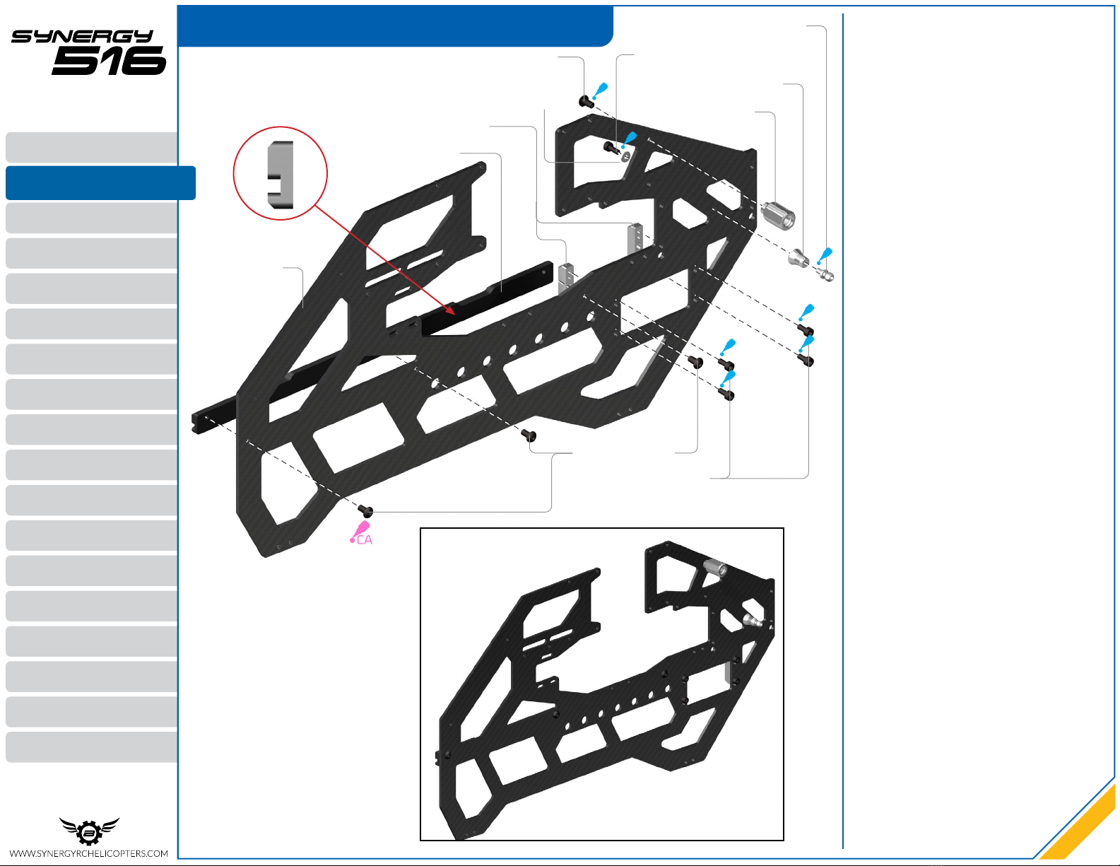
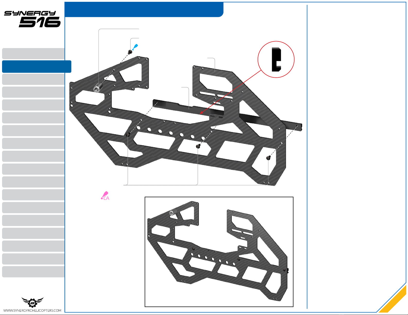
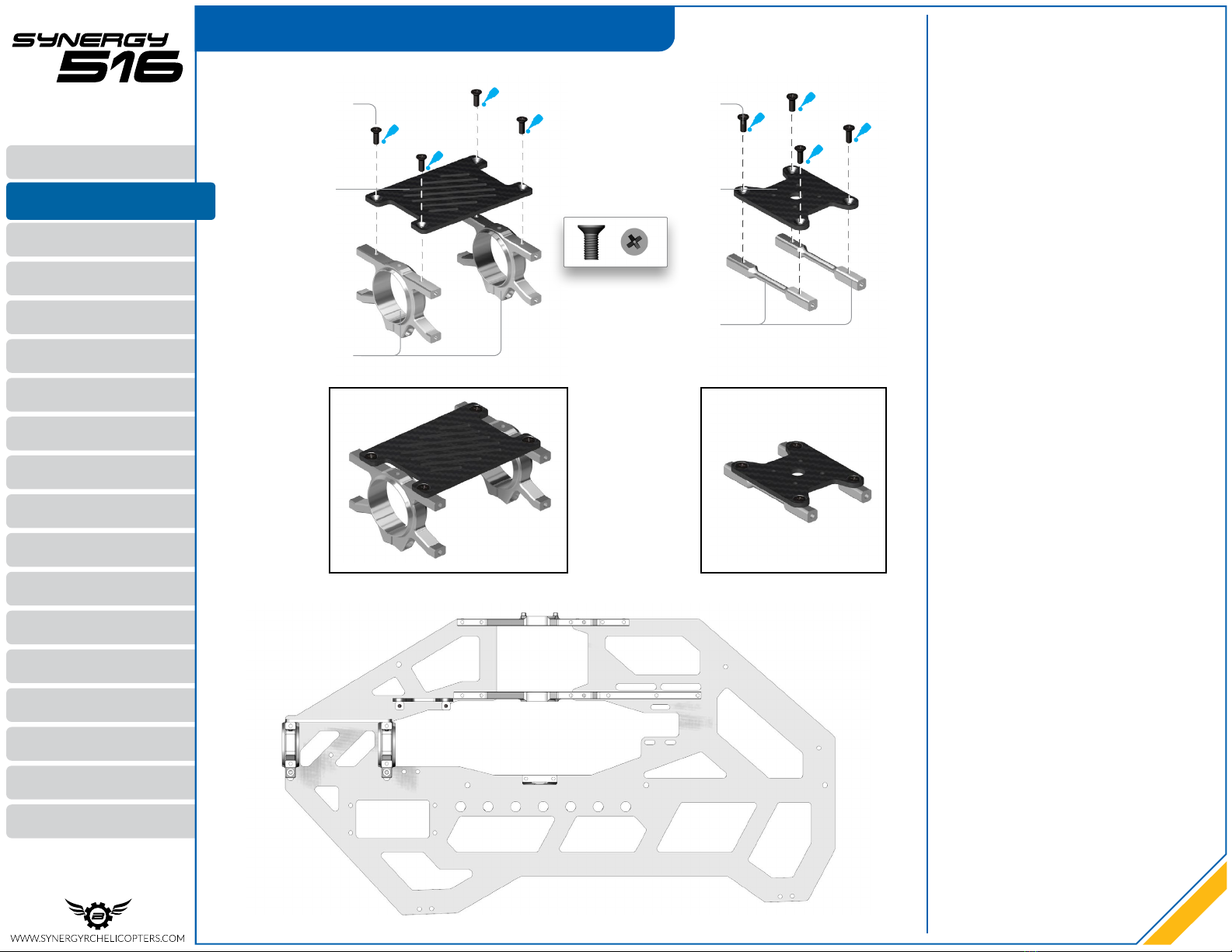
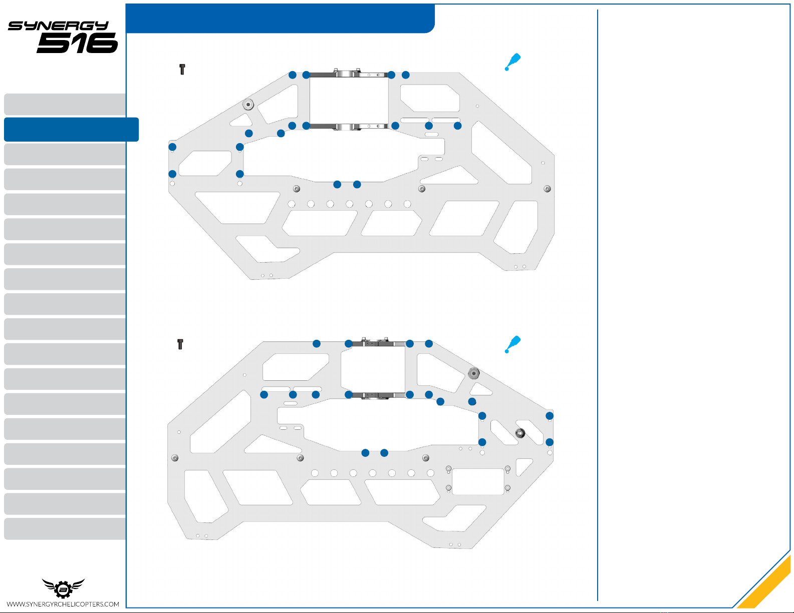
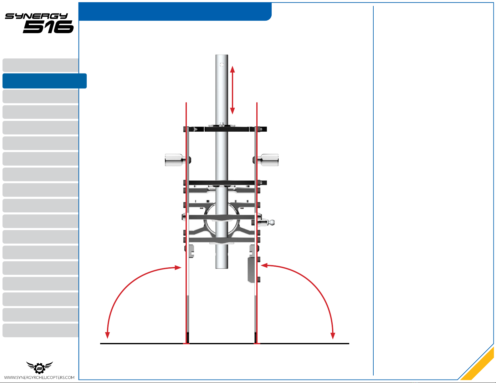
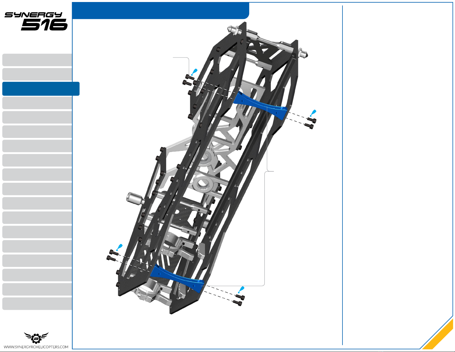
02 | FRAME
03 | LANDING GEAR
04 | BELT TENSION ARM
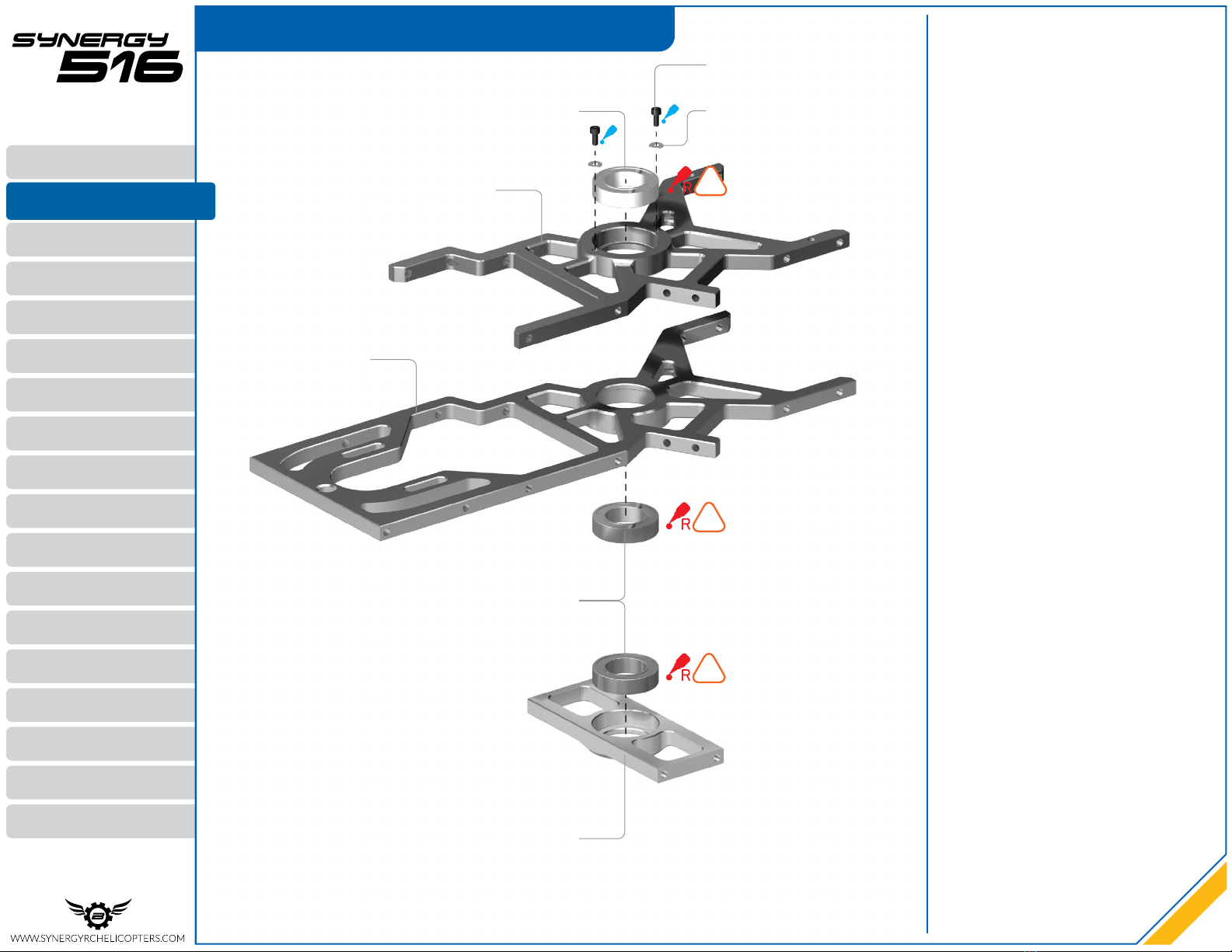
05 | MAIN DRIVE
06 | BOOM INSTALLATION
07 | TAIL ASSEMBLY
08 | SETTING BELT TENSION
09 | SWASH PLATE
10 | CYCLIC SERVOS
11 | ANTI-ROTATION GUIDE
12 | TAIL SERVO
13 | MAIN HEAD
14 | PITCH LINKAGES
15 | MOTOR INSTALLATION
16 | BATTERY TRAY & CANOPY
17 | BLADE INSTALLATION
18 | COMPLETE MODEL
01 | INTRODUCTION
2
Rev 1.0M
INTRODUCTION