Synergy NSC CONTENDER User manual


Congratulations on your purchase of the Synergy N5c radio controlled helicopter kit. The Synergy N5c was
designed and developed by Botos Design & Distribution Inc.. The design of the Synergy N5c emerged from
many years of experience in the hobby including design, research & development, and last but not least
as a world class pilot who truly enjoys this wonderful hobby.
This radio controlled helicopter is NOT A TOY. It is a sophisticated piece of equipment and was designed
and intended for hobby use only. If not properly assembled, maintained or operated, it is capable of
causing property damage and bodily harm to both the operator and/or spectators. Botos Design &
Distribution Inc., its affiliates and its authorized distributors assume no liability for damage that could occur
from the assembly or use/misuse of this product. If you are new to the hobby we strongly recommend
seeking the help and advice from an experienced modeler.
Operating a model helicopter requires a high degree of diligence and skill. If you are new to the hobby, it
is best to seek help and guidance from experienced radio controlled helicopter pilots. This will both greatly
speed up the learning process and make it much safer for you.
For those pilots who will be operating their Synergy N5c in the United States, we strongly recommend
joining the AMA. The AMA is a non-profit organization that provides services to the model aircraft pilots. As
an AMA member, you will receive a monthly magazine entitled Model Aviation and most importantly a
liability insurance plan to cover against possible accident or injury. All AMA charter aircraft clubs require
individuals to hold a current AMA sporting license prior to operation of their models
For further information, you can contact the AMA at
Academy if Model Aeronautics
5151 East Memorial Drive
Muncie, IN 47302
(317) 287-1256

TABLE OF CONTENTS
A1
Fuel Tank Assembly
A2
Landing Gear Assembly
A3
Engine / Clutch Assembly
A4
Clutch Bell & Start Shaft Assembly
A5
Servo Tray Assembly
A6
Right Frame Support Assembly
A7
Bearing Block Assembly & Installation
A8
Servo Tray Installation
A9
Clutch Stack & Belt Idler Installation
A10
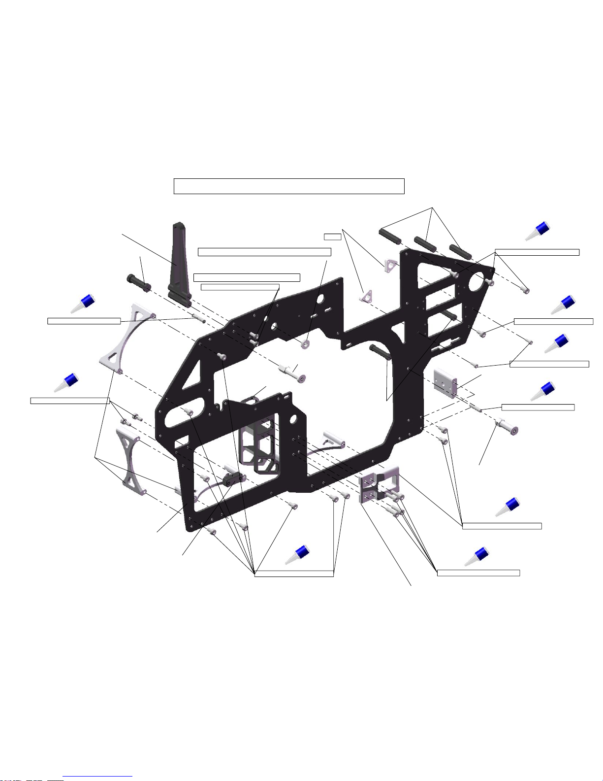
Left Frame Assembly Step 1
A11
Left Frame Assembly Step 2
A12
Frame Alignment
A13
Landing Gear & Fuel Tank Install
A14
Engine Installation
A15
Fan Shroud Installation
A16
Cyclic Control Assembly
A17
Cyclic Bell Crank Installation
A18
Belt Drive Tail Box Assembly 1-2
A19
Belt Drive Tail Box Assembly 3
A20
Tail Rotor Hub Assembly
A21
Pitch Slider Assembly
A22
Tail Pitch Slider & Tail Rotor Hub Install
A23
Belt Drive Tail Pushrod & Guides
A24
Belt Drive Tail Boom Installtion
A25
Boom Support Assembly
A26
Tail Box Assembly for Torque Tube
A27
Tail Bell Crank Assembly
A28
Tail Rotor Hub & Pitch Slider Installation for Torque Tube
A29
Torque Tube Assembly
A30
Tail Boom to Torque Tube Assembly
A31
Torque Tube Tail Section Completion
A32
Torque Tube Input Transmission Assembly
A33
Input Transmission Installation
A34
Tail Boom Install
A35
Main Gear and Main Pulley Assembly
A36
Main Belt Pulley & Main Gear Installation
A37
Belt Drive Train Install Step 2
A38
Crown Gear Assembly
A39
Crown Gear & Main Gear Install
A40
Auto Hub Bolt Install
A41
Crown Gear Hub Pin Install
A42
Crown Gear Mesh Adjustment
A43
Tail Servo & Linkage Assembly
A44
Flybar Head Block Assembly
A45
Swashplate & Washout Assembly
A46
Flybar Blade Grip & Rotor Head Assembly
A47
Rotor Head to Swashplate Assembly
A48
Rotor Head Installation
A49
Flybarless Head & Inner Swash Driver Assembly
A50
Flybarless Head Installation
A51
Elevator Servo Linkage
A52
Aileron Servo Linkage
A53
Pitch Servo Linkage
A54
Throttle Servo Linkage
A55
Radio Plate
A56
Canopy and Rotor Blades

Tools Required For Assembly
Equipment Required For Assembly (not included)
Transmitter (6-channel or more, helicopter)
•
Receiver (6-channel or more)
•
Standard Servos x3 (cyclic servos)
•
Mini Servo x1(Futaba 9650 or 9257 for throttle
•
High Speed Tail Servo x1
•
Heading Lock Gyro or Flybarless System x1
•
50-55 Nitro Engine x1
•
50-55 Muffler x1
•
Pitch Gauge
•
Engine Starter with Starting Wand x1
•
2S 1800mah Lipo Battery for Regulator x1
•
6v Regulator x1
•
600-625mm Main Rotor Blades
•
85-95mm Tail Rotor Blades
•
Silicone Fuel Tubing
•
Helicopter Fuel 15-30%
•
Glow Plugs
•
Needle Nose Pliers
•
Diagonal Cutting Pliers
•
Phillips Screw Driver Set
•
Hex Drivers 1.5/2/2.5/3
•
Scissors
•
Grease
•
CA Glue
•
Loctite - Blue & Red
•
JB Weld
•
Metric Ruler
•
Boto-Sizer Ball Link Sizing Tool (Part# 700-001)
•

610-330 Fuel Tank
110-332 Fuel Clunk
110-333 Fuel Clunk Tubing
110-331 Fuel Tank Stopper
106-810 Fuel Tank Stopper Grommet
Complete Fuel Tank
Fuel Tank Assembly
A1
Trim fuel tubing to 65mm or desired length
so that fuel clunk reaches to the rear of
fuel tank.
ITEM NO.
PART NUMBER
DESCRIPTION
QTY.
1
N5 Fuel Tank
1
2
N5 Fuel Tubing
Grommet
1
3
N5 Fuel Clunk
Tubing
1
4
N5 Fuel Clunk
1
5
N5 Fuel Tank
Stopper
1

A2
Landing Gear Assembly
Complete Landing Gear
101-308 M3x8 Button Head
610-324 Landing Gear Strut
610-322 Skid Tube Lock x4
610-321 Skid Tube
Screw Skid Tube Lock Down
on to flybar then secure within
Skid Tube
106-966 Skid Tube Plug x4
ITEM NO.
PART NUMBER
DESCRIPTION
QTY.
1
N5 Landing Gear V2
2
2
N5 Skid Tube
2
3
N5 Skid Tube Lock
4
4
M3 x 0.5 x 8 Button
Head
4
5
N5c Skid Tube Plug
4

Engine Clutch Assembly
A3
50 - 55 Sized Engine(not included)
610-1172 Fan Hub
100-312 M3x12 Socket Head
Engine Nut(not included) See Note*
Engine Washer(not included)
610-171 Cooling Fan
101-306 M3x6 Button Head x4
610-160 Clutch
108-110 8x12x12 One Way Clutch
M4x8 Socket Head x2
107-104 2mm Pivot Ball Long
100-252 M2 Nylock Nut
(Factory Installed)
Fan Hub install note- Important!
1. Slide Fan Hub on to crank shaft then take up
end play with engine nut.(engine washer manditory!)
2. Tighten down pinch bolts evenly.
3. Insert crank locking tool (not included) and
finish tightening engine nut. Do not over tighten
crank shaft nut, only snug! It is possible to distort
fan hub by over tightening.
Tested with -
- O.S. 50 Hyper
- O.S. 55HZ
- YS56
ITEM NO.
PART NUMBER
DESCRIPTION
QTY.
1
OS50sxh
1
2
Servo Horn
1
3
N5 2mm Pivot Ball
1
4
M2 x 0.4 Nylock Nut
1
5
N5 Fan Hub
1
6
M3 x 0.5 x 12 Socket
Head
2
7
N5 Cooling Fan
1
8
M3 x 0.5 x 6 Socket
Head
4
9
N5 Clutch
1
10
M4 x 0.7 x 8 Socket
Head
2
11
N5 One Way Clutch
Bearing
1
12
Engine Nut
(Included with
Motor)
1

Clutch Bell & Start Shaft Assembly
A4
106-326 26mm Hex Standoff x2
106-955 Hex Adapter
100-466 M4x6 Set Screw
610-162 Start Shaft
108-615 6x15x5 Radial Bearing
110-155 Clutch Bearing Block
108-105 10x19x5 Radial Bearing x2
610-120 20T Pinion Gear
610-125 Clutch Bell, Lite
108-614 6x12x4 Radial Bearing
110-158 Clutch Lining
Factory Installed
Factory Installed
Factory Installed
Install governor magnet before assembly
ITEM NO.
PART NUMBER
DESCRIPTION
QTY.
1
N5 Clutch Bell
1
2
N5 6x14x4 Bearing
1
3
N5 Start Shaft Top
1
4
N5 20T Pinion gear
0.7M
1
5
N5 Clutch Lining
1
6
N5 10x19x5 Main
Shaft Bearing
2
7
N5 Clutch Bearing
Block
2
8
N5 6x15x5 Radial
Bearing
1
9
N5 Hex Adapter
1
10
N5 Set Screw M4 x
0.7 x 5
1
11
N5 26mm Hex Stand
Off
2

13.50
13.50
Servo Tray Module Assembly
A5
107-104 2mm Pivot Ball Long x6
610-210 Servo Tray Module
106-326 26mm Hex Stand off
Digital Servo(not included)
106-115 Servo Hold Down
100-212 M2x12 Socket Head x12
100-252 M2 Nylock Nut x6
Servo Horn
Servo Screw(included with servo)
Pivot Ball Mount Distance
For optimal performance pivot
balls should be mounted between
13.5mm from the center of the servo.
If you are running a flybarless configuation
you may want to consider 10mm for
better resolution.
ITEM NO.
PART NUMBER
DESCRIPTION
QTY.
1
N5 26mm Hex Stand
Off
4
2
servo_tray
1
3
N5 Servo Hold
Down
6
4
M2 x 0.4 x 12 Socket
Head
12
5
N5 2mm Pivot Ball
6
6
M2 Nut
6
7
x x
8
x x
9
x x
10
x x

100-306 M3x6 Socket Head
100-312 M3x12 Socket Head
110-226 Tail Bell Crank Block
610-313 Arc Brace x4
610-422 Canopy Stand Off
610-133 Motor Center Block, Lite
610-312 Frame Connector Block
100-306 M3x6 Socket Head
108-484 4x8x3 Flange Bearing
120-122 Anti-Rotation Guide
610-223 3x26 Threaded Spacer
100-376 M3x16 Set Screw
101-308 M3x8 Button Head
Right Frame Support Installation
A6
610-311 N5C Main Frame
100-308 M3x8 Socket Head
Flange oriented on outside of frame
Do not over tighten in plastic
100-206 M2x6 Socket Head
610-123 Tail Servo Mount
610-124 N5C Front Frame Spacer
Large
100-306 M3x6 Socket Head
610-224 3x6x26 Frame Spacer
100-376 M3x16 Set Screw
610-423 Canopy Stand Off, Front
610-126 Motor Mount Lite
100-266 M2.5x6 Socket Head

100-308 M3x8 Socket Head
A7
108-106 10x19x6 Radial Bearing
108-819 8x19x6 Radial Bearing
Bearing Block Assembly & Installation
510-542 Main Shaft Bearing Block, Lite
DO NOT FULLY TIGHTEN
THESE BOLTS YET!
ITEM NO.
PART NUMBER
DESCRIPTION
QTY.
1
10x19x6 Radial
Bearing
1
2
8x19x6 Radial
Bearing
1
3
N5 Main Shaft
Bearing Block Metal
2

Servo Tray Installation
Do not fully tighten screws!
A8
100-306 M3x6 Socket Head

100-310 M3x10 Socket Head
106-930 M3 Step Washer
106-952 Governor Sensor Mount
200-404 Clutch Bell, Lite Assembly
Install governor sensor at this time.
X2
Belt Idler for Belt Drive System Only
101-306 M3x6 Button Head
100-320 M3x20 Socket Head
610-319 Idler Brace
610-317 Idler Mount Block
A9
108-384 3x8x4 Radial Bearing
610-318 Belt Tension Idler
109-352 3x5x2 Brass Spacer
108-384 3x8x4 Radial Bearing
Clutch Bell & Belt Idler Installation
Belt Idler Assembly

108-484 4x8x3 Flanged Bearing
610-323 Landing Gear Mount Block
100-310 M3x10 Socket Head
Left Frame Side Assembly
610-311 Main Frame
Install Bearing Flange to outside of frame
A10
Step #1
610-122 Throttle Servo Mount
100-206 M2x6 Socket Head
101-306 M3x6 Button Head
610-317 Idler mount Block

100-306 M3x6 Socket Head
100-308 M3x8 Socket Head
610-323 Landing Gear Mount Block
100-310 M3x10 Socket Head
101-308 M3x8 Button Head
100-376 M3x16 Set Screw
610-422 Canopy Stand Off
100-306 M3x6 Socket Head
100-354 M3 Washer
100-310 M3x10 Socket Head
Do not over tighten in plastic
Do not tighten bolts completely
until next step.
Left Frame Assembly
100-306 M3x6 Socket Head
A11
Step #2
100-376 M3x16 Set Screw
610-423 N5C Canopy Stand Off, Front
100-306 M3x6 Socket Head
Belt Idler Assembly
100-320 M3x20 Socket Head
100-266 M2.5x6 Socket Head
100-306 M3x6 Socket Head

90°
Frame Alignment
With all bolts slightly loose, place
frameset on a flat surface. Slide
main shaft into main shaft bearing
blocks to make sure the main shaft
spins freely. Be sure that side frames
are 90 degrees to the flat surface.
Once you have achieved the correct
frame alignment you may finish
tightening frame bolts.
(Front view)
A12

Landing Gear & Fuel Tank Installation
Fuel Tank Assembly
106-807 Tank Edge Grommet
Landing Gear Assembly
100-316 M3x16 Socket Head
A13
110-419 Fuel Tubing Grommet, Frame

Engine Installation
A14
50-55 Sized Motor
610-126 Motor Mount, Lite
M3x12 Socket Head
606-305 Motor Spacer
Note - Ensure engine is vertically
aligned with clutch stack. Start
shaft should rotate freely, and
bottom of clutch should be parallel
with bottom of clutch bell.

610-342 Fan Shroud Right
610-343 Fan Shroud Left
100-312 M3x12 Socket Head
100-210 M2x10 Socket Head
100-312 M3X12 Socket Head
Fan Shroud Installation
Do not over tighten!
A15
610-224 3x6x26 Threaded Frame Spacer

107-106 Short Pivot Ball
108-483 4x8x3 Radial Bearing
610-221Bell Crank (Aileron & Pitch)
Bell Crank Assembly
Note orientation of boss
before assembly of pivot
ball to bell crank.
101-306 M3x6 Button Head
610-228 Bell Crank Spacer
610-225 Bell Crank Shaft
107-106 Short Pivot Ball
100-464 M4x4 Flat Point Set Screw
610-222 Outside Elevator Bell Crank
610-226 Inside Elevator Bell Crank
Do not fix bell cranks to shaft until
the next page where they will fit into
the frame.
A16
X2
ITEM NO.
PART NUMBER
DESCRIPTION
QTY.
1
N5 Bell Crank Shaft
1
2
N5 Bell Crank AP
2
3
4x8x3 Bearing
4
4
N5 4.5 Pivot Ball
9
5
M3 x 0.5 x 6 Button
Head
1
6
N5 Bell Crank
Spacer
1
7
N5 Bell Crank
Elevator Inside
1
8
N5 Bell Crank
Elevator Outside
1
9
B18.3.6M - M4 x 0.7 x
4 Hex Socket Flat Pt.
SS --N
2
Table of contents
Other Synergy Toy manuals
Popular Toy manuals by other brands

Multiplex
Multiplex EXTRA 330 LX Assembly instructions

LEGO
LEGO Elves 41077 manual

TSA model
TSA model INFUSION 700N instruction manual

LEGO
LEGO dc universe super heroes 6860 Building instructions

Hasbro
Hasbro Nite Brite Nemo 3161 instruction manual

Snelflight
Snelflight Hoverfly Instruction and maintenance manual