WWW.SYNERGYRCHELICOPTERS.COM 3
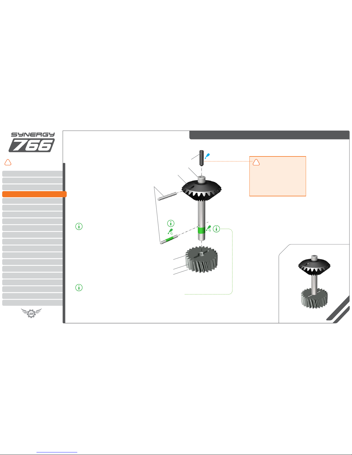
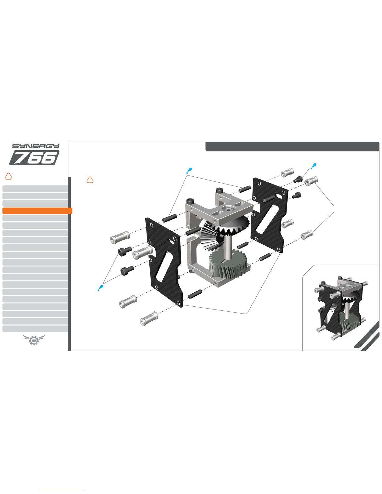
Components that are factory assembled
provide a reference for model assembly.
Disassembly and application of thread
lock is required where indicated.
!
FRAME SIDE 1
FRAME SIDE 2
LANDING GEAR
SPECIFICATIONS
TRANSMISSION
MAIN BEARING BLOCKS
BATTERY TRAY
TORQUE TUBE / BOOM / CONTROL ROD
MAIN AND TAIL BLADES
PANEL SYSTEM
OPTIONS AND CONFIGURATIONS
MAIN DRIVE
SWASH PLATE
SWASH PLATE LINKAGES
MOTOR
HEAD ASSEMBLY
PITCH LINKAGES
SERVO INSTALLATION
TAIL AND HUB
INTRODUCTION
SPECIFICATIONS
SPECIFICATIONS AND FEATURES
• Main Blades: 716-806mm
• Available Main Gear Ratio: 9.27-11.58*
• Available Tail Gear Ratios: 4.5 / 4.7 / 5.1*
• Available Boom Sizes: 716 / 766 / 806*
• Tail blades: 106-116mm
• Battery Conguration: 12s-14s
• 64mm frame width
*This kit includes the following:
• 13T main pinion
• 4.7 tail ratio (27T Pinion). See page 8.
• Boom, torque tube, and tail control rod lengths optimized for
766mm main blades. See pages 64-67 for specic sizes.
Optional parts are available from the Synergy RC Helicopters
website at http://www.mattbotos.com/store.
Main and tail blades are not included.
SPECIFICATIONS: MAIN FEATURES:
• CNC Machined Helical mod 1 main and auto gears
• Monster-mod 1.25 24T front and rear tail drive bevel gears
• Torque tube tail drive for high efciency
• Ultra-wide head for rigid, precise control
• Tunable blade grip pitch arm geometry
• 12mm Main Shaft / 10mm Spindle & rocker support
• Dual main shaft thrust bearings
• Serviceable dual-bearing swash plate system
• Quad progressive & adjustable head dampening
• Turnbuckle linkage adjustments
• Low disk loading
• Multiple tail drive ratios
• Locking battery tray with CG adjustment
• Optimized tail arm geometry
• Optimum boom options for each blade size
• 3 panel canopy system with high-visibility paint
• Grease ports for all 6 thrust bearings
• CNC Machined Delrin gears
• Designed and supported in the U.S.A