Synesso Cyncra 2016 User manual

2016 CYNCRA OWNER’S MANUAL
5610 4th Ave. S. Seale, WA 98108 U. S. A.
(t)+1. 206.764.0600 (f) +1. 206.764.0601
www.synesso.com
Last Revision: 5-2018

2
TABLE OF CONTENTS
Introducon 3
Safety Warnings 4
Warranty & Water Standards 5
Installaon 6-7
Installaon Prep Guides 8-9
Plumbing Requirements 10
Electrical Requirements 11
Operaon 12-14
Machine Opons 14-15
Programming Machine Funcons 16-21
Brew Temperature Control 17
Auto Flush 18
Steam Temperature Control 19
Hot Water Tap / Serial Number 20
Error Codes 21
Maintenance 22-23
Troubleshoong 24-26

3
INTRODUCTION
These are Original Instrucons. Congratulaons on the purchase of your Synesso™ Cyncra 2016 espresso
machine. Please read this Owner’s Manual and retain it in a safe locaon for future reference. If you have
any quesons about your machine, please contact Synesso™ and our knowledgeable sta will assist you.
Included in the package with this machine you will nd the following:
Thumb Drive containing the Owner’s Manual and other technical documents
Pump/Motor Combinaon + hoses (3/8” compression ngs on all hoses)
8’ Flexible ¾” ID drain hose + hose clamp (aached)
Fing, 1/4” male NPT x 90° x 3/8” Compression (if not CE/C-Tick)
Accessory Package: Portalters (per customer specicaon), blind basket, Synesso™ 3 oz. (90ml) shot
glass, JoeGlo™ cleaning kit, 58mm tamper, 4 rubber leg pads
Electrical plugs are ONLY included on CSA Cered machines (Canada). For all other machines, the
owner of the machine must purchase an appropriate plug end for their machine.
Serial Number
Your espresso machine has a unique serial number, located on the le inner frame of the machine, just
under the drain tray on a serial plate. The number can also be read on the display during start-up or on the
“Synesso” screen (see page 18). Please have this serial number available for reference when contacng
the factory.
Understanding the informaon displayed in the serial number. i.e.: 307152350
3 - is the number of groups on this machine (this is a 3 group machine)
07 - is the month it was built (July is 07)
15 - is the year it was built (15 is the year 2015)
2350 - is the machine sequence number for all machines built by Synesso
Please have your Serial Number available
BEFORE calling for service or technical support.
Thank you.
S/N: ________________________________
The OFFSETS for this machine are:
BG1: _____°F / BG2:_____°F / BG3:_____°F
Steam Tank:_____°F
Factory Contact Informaon:
Synesso™ Inc.
5610 4th Ave South
Seale, WA 98108 - USA
Tel: +1.206.764.0600 / Fax: +1.206.764.0601
E-mail: [email protected]
Web: www.synesso.com
Twier: @SynessoFactory
Instagram: Synesso_factory
Facebook: Synesso Factory Temperature Sengs:
Brew Tanks: 203 F (95 C) Steam Tank: 250 F (129 C)

4
The conductors of the power supply cord are
marked “L1”, “L2” for the ungrounded (“hot”)
supply conductors and “G” for an equipment
grounding lead.
Warning: Risk of Fire. Use UL Listed Grounding
Type Plug rate for 220 Volts, ______ Amperes,
_______ Phase, #______ Wire. Plug to be Selected
and Installed only by Qualied Service Personnel.
Electrical
WARNING: Disconnect from
power supply before servicing
AVERTISSEMENT: Couper
l’alimentaon avant l’entreen
et le depannage.
California
only:
CALIFORNIA PROPOSITION 65 WARNING
WARNING: This product contains chemi-
cals known to the State of California to
cause cancer and birth defects or other
reproducve harm. (California law require
this warning to be given to customers in
the State of California)
Electrical
Box:
This equipment is to be installed to
comply with the applicable federal,
state or local plumbing codes.
Under drain
tray
Materials informaon for Synesso™machines:
All stainless steel coming into contact with the water supply is 300 series
All brass ngs are low lead per the CA360 specicaons or beer
All electronic devices are lead free
All gaskets are made from food-contact safe material
Test Informaon
Brew (coee) tanks are hydrostacally tested to 375 psi
Steam tanks are pressure tested to 75 psi
The electrical system is subject to an electrical withstand test of:
1.20 kvac, at 5.00 mA, for 1 second
IMPORTANT Informaon for Synesso™ Espresso Machines: DISCONNECT FROM POWER BEFORE SERVICING.
Read the enre manual before operang this machine.
Steam and condensaon from the steam wand discharge are very hot and may cause burns.
The steam wand ps and bases become hot during use: do not touch these surfaces.
Cover the steam wand p or submerge in a lled pitcher to safely divert the steam before opening the
steam valve.
Never remove the steam wand from the product that is being heated when the valve is open.
Never remove the portalter from the machine during the acve brewing process.
Keep water and moisture away from any electrical device or live power.
Steam tank water is heated to 260°F (126°C) or more; Use cauon near steam tank.
The brew groups deliver water as hot as 210°F (99°C). Avoid exposure to this water.
The hot water mix valve can be adjusted to deliver water as hot as 212°F (100°C), which can cause severe
burns: please use cauon when acvang this water source.
Safety Label Locaons:
Synesso™complies with UL regulaons by posng the following labels on its machines:
SAFETY WARNINGS

5
Limited One-Year Non Wearing Parts Warranty
Synesso, Inc and/or your Distributor warrants to the original purchaser that Synesso espresso machines are
free from defects in materials and workmanship under normal use and service for the period commencing
upon the date of shipping and connuing for 12 months from the original date of shipment. Synesso will
make a good faith eort for prompt correcon or other adjustment with respect to any non wearing part
that proves to be defecve within the limited warranty period. This Limited Warranty is condional upon
proper use of the machine by the purchaser.
This Limited Warranty does not cover defects or damage resulng from: accident, misuse, abuse, shipping
damage, neglect, unusual physical, electrical or electromechanical stress, unauthorized customer modica-
ons or improper water ltraon.
Proper water ltraon and regular lter changes are a requirement to keep your factory warranty valid
and your machine funconing properly. It is highly recommended that you contact a professional water
ltraon specialist in your area and have your water tested to determine the proper ltraon system. It is
important to note that many municipalies change their water sources throughout the year, so addional
water tests may become necessary.
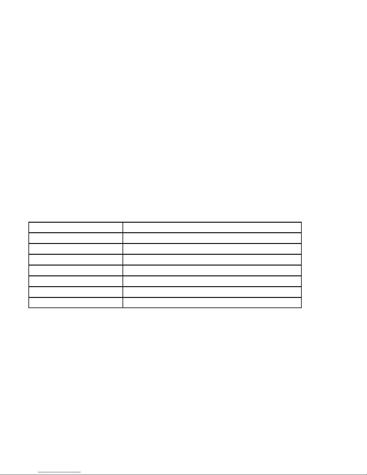
Water Standards to keep your warranty valid:
In Synesso’s experience, Everpure Claris and Cirqua formulator systems can produce a re-
sult that can damage the Synesso stainless steel tanks. Use of either system is highly dis-
couraged and will void the water related parts of the machine warranty.
Any part which is determined to be defecve in materials or workmanship should be returned to Synesso or
to an authorized service locaon, shipping costs to be determined depending upon the circumstances.
Synesso may repair or replace the product or part with new or factory refurbished equipment at Synesso’s
sole discreon. If the product or part is determined to be defecve and in compliance with the Limited War-
ranty condions, the replacement part or product will be returned to the purchaser with shipping prepaid.
.
Many jurisdicons have codes and regulaons governing sales, construcon, installaon, and/or use of
products for certain purposes, which may vary from area to area. While Synesso aempts to assure that its
products comply with such codes, it cannot guarantee compliance and cannot be responsible for how the
product is used or installed.
Total Dissolved Solids (TDS) 30 to 200 ppm (parts per million)
Total Hardness - in ppm Less than 85 ppm
Total Hardness – in grains 3 to 5 grains (divide ppm by 17.1 to get grains)
pH 6.5 pH to 7.5 pH
Chloride 0 ppm – any Chlorides can be corrosive and harmful
Total Alkalinity Less than 100 ppm
Chlorine 0 ppm
Iron 0 ppm
WARRANTY & WATER STANDARDS

6
WARRANTY & WATER STANDARDS
Synesso’s liability is limited to the purchase price of the product and shall not be held liable for damages that
extend beyond the product itself. Synesso’s liability of consequenal, incidental damages, indirect or direct
damages for personal injury, inability to properly use this product, loss of business prots or interrupon to
business is expressly disclaimed.
** Regarding equipment sold or residing outside the United States: purchaser maybe required to pay for the
shipping and associated costs for warranty parts, repairs and services. Please contact your local distributor to
resolve the issue regionally, if possible.
INSTALLATION & WORK STATION
To maintain the 1 year warranty, an authorized or cered espresso service representave
must perform the installaon of this espresso machine.
Site Preparaon - See Diagram on page 7. The machine must be placed on a level horizontal surface that
can be easily cleaned and is capable of sustaining a minimum of 300 lbs.
The counter top requires a depth of 28”, which provides a minimum clearance of 1” behind and 3” in front
of the machine.
The height of the surface can vary to suit the operator.
Make a 2 ½” minimum diameter hole through the counter top located 4” from the rear and 7” from the right
side of the machine. The hoses, drain tube, and electrical lines will all pass through this hole.
A 3/8” min. diameter cold water supply line from the lter with a shut o valve is required within 5’ of the
machine. The valve should be easily accessed for machine service.
The machine supply hose and pump ngs are 3/8” tube compression ngs.
A proper water ltraon or soening system must be installed on the incoming water supply. Water treat-
ment requirements will vary, and it is important to use a system designed to match the needs of your spe-
cic area. Water ltraon systems require periodic maintenance, including cartridge or lter replacement.
Proper ltraon and service is vital to the funcon of the machine and the quality of the espresso served.
Follow the instrucons provided by your water treatment system for proper installaon.
Note: Improper water ltraon can result in severe damage to the machine including scale deposits and cor-
rosion. DAMAGE CAUSED BY IMPROPER WATER TREATMENT WILL NOT BE COVERED BY THE MACHINE
WARRANTY. See page 5.
There must be adequate room under the counter to locate each motor and pump. The pumps must be easily
accessible for adjustment and motors must have a minimum of 3” clearance on all sides for air ow.
A oor drain or sink must be available. The best locaon is directly under the machine. The 3/4” drain hose
should descend as vercally as possible for opmal drainage. An air gap is required between the end of the
drain hose and the highest water posion of a clogged drain. This is to prevent the possibility of drain water
backing up into the machine.

7
INSTALLATION & WORK STATION

8
Easily Accessible
50 PSI (3.5 Bar)
30 GPH (120 LPH)
(230 V / 5956 Was)
(3.5 Bar)

9

10
PLUMBING REQUIREMENTS
This equipment must be installed to comply with the applicable federal, state or local plumbing codes.
WATER TREATMENT IS REQUIRED TO PRESERVE THE FULL MACHINE WARRANTY. Please ensure that the
incoming water complies with the warranty requirements listed on page 5.
Using the provided stainless steel braided hose, connect the pump to the shuto valve on the ltered cold
water line. Fings on the hoses and pumps are 3/8” tube compression. Thread sealant or Teon tape is
not necessary. Make connecons snug, but do not over ghten.
Turn incoming water ON and check for leaks.
Synesso™machines require a minimum of 50 PSI (3.5 bar) of line pressure at 30gal (120L) per hour to have
the auto-ll system for the steam tank funcon properly. Please ensure that the incoming water meets
this requirement or contact Synesso™for alternave methods of boosng water pressure.
NOTE: Synesso™sells a “Euro-hose” adaptor hose and ng (part number is 1.5020) which converts from a
3/8” tube ng to a pipe ng, suitable for most non-US plumbing. Please refer to the picture below to
idenfy the dierences between the standard and Euro-style ngs and hoses.
1/4” NPT
3/8” Tube Compression
3/8” BSP Pipe
Standard Hose
and Fing
Euro Hose
and Fing

11
ELECTRICAL REQUIREMENTS
All Synesso™machines are rated to operate on 220v / 60 Hz or 230v / 50 Hz frequency, single phase. Ma-
chines will operate between 208v and 240v.
Listed amp rangs are all measured at 220v. Incorrect voltage can cause malfuncon or damage to the
machine. Plug or means of isolaon must be easily accessible.
An electrical socket and matching plug, rated at the proper voltage and amperage are required within three
feet of the machine. Plug ends are NOT included with the machine unless required by CSA or other cerca-
on.
Aach the plug end per manufacturer’s instrucons.
Make sure that the red electronics switch and the heang element breaker on the front of the electrical box
are in the OFF posion, then plug the power cord into the receptacle.
Reghten side panel fasteners aer service to ensure proper earth grounding.
OPTIONAL: If recovery me is slow, install an In-Line Buck-Boost transformer to increase voltage below 208v
to opmize machine recovery me. Buck-boost transformers come in dierent sizes. Please choose the ap-
propriate one for your machine if required. 1 and 2 Group Machines require a 1.0 KVA transformer, 3 Group
Machines require a 1.5 KVA transformer.
SPECIAL ELECTRICAL INFORMATION FOR EMC-COMPLIANT MACHINES
(C-TICK FOR AUSTRALIA, CE FOR EUROPE AND OTHER LOCATIONS)
To comply with EMC (Electromagnec Compability) regulaons, Synesso™is required to install a capacitor
in the electronics box across the main power IN. To avoid an electric shock from the charge held in the ca-
pacitor, unplug or isolate the machine with the electronics ON/OFF red rocker switch in the ON posion.
North American Wire Color Worldwide Wire Color
Green Ground Green and Yellow Ground (Earth)
White 110v Line 1 Brown 230v
Black 110v Line 2 Blue Neutral
Model Cord Plug Rang (UL Listed) Machine Max Amp Draw Machine Max Was
2 Group Cyncra 30 amp 28 amp, 220v / 60 Hz 5956 Was, 230v / 50 Hz
3 Group Cyncra 50 amp 36 amp, 220v / 60 Hz 7742 Was, 230v / 50 Hz

12
OPERATION
Start-Up Instrucons
1. To ll the machine, connect the water lines, set the drain hose and turn the water ON.
2. Switch the red electronics On/O switch to ON. This acvates the machine’s water auto-ll feature for
the steam tank and the electronics, but NOT the heang elements.
3. The water level sight glass for the steam tank is located on the right side of the machine. As the tank lls,
the water level will rise in the sight glass and will automacally stop when the preset level is reached.
4. Bleed the group heads of air. Turn each group head handle le into the BREW posion, (see pictures be-
low) allow the group to run unl there is a steady ow of water. Return the group head to the OFF posion.
5. Wait unl the steam tank has stopped lling and the level in the sight glass reads at least ½ full. Turn the
heang element breaker to the ON or (1) posion. All the heang elements (brew and steam) are now ac-
vated.
6. To adjust the pump pressure, acvate the pump by turning the brew group to the BREW posion.
7. Locate and read the pump pressure / brew gauge located to the right of the rightmost group
8. Set the pump pressure to 9 Bar:
Locate the pump adjusng screw on the right side of the brass pump housing.
Loosen the lock nut and turn the screw with a screwdriver:
Clockwise to INCREASE pressure
Counterclockwise to DECREASE pressure
Once the desired pressure is reached, reghten the lock nut.
9. Please allow at least 30 minutes of “warm up” me before using your Synesso™espresso machine to
brew shots or steam milk. The steam gauge (the le hand gauge) should read a minimum of 1.1 Bar.
O Pre-infusion Brew

13
OPERATION
Prepare a Portalter
1. For best results, use fresh coee. Ground coee should be brewed as soon as possible aer grinding.
2. Select the correct spout and basket conguraon. Single, double and boomless portalters are available
through Synesso™. The single spout portalter is used with a single (7g) basket to brew a single shot. The
double spouted or boomless portalters can be used with double (14g) or triple (18g or 21g) baskets to
brew triple, double, or 2 single shots of espresso.
3. Fill the portalter basket just above level and wipe o the excess.
4. Press straight down evenly on top of the grounds with the tamper.
NOTE: When not in use, keep the portalter engaged in the group head to keep it warm.
Espresso Brewing
1. Grind a dose of coee appropriate to the basket you will be using.
2. Dispense into the portalter basket.
3. Level the mound and compress using a tamper. (A tamper is supplied with the machine.)
4. Engage the portalter into the brew group that has the correct temperature seng for this espresso roast
and pull rmly to the right to set the seal.
5. Pre-infuse the coee puck by turning the brew group clockwise to the center posion. This allows line
pressure to saturate the puck.
NOTE: If a stage 1 (pre-infusion) is set on the display, that will begin automacally when the actuator is
switched to the brew posion, so the pre-infusion posion should be skipped.
6. When a drip shows at the spout (or on the basket if boomless), Turn the group cap clockwise again to the
brew posion. This engages the pump.
7. When the stream of coee turns from brown to “blonde”, end the shot by returning the group cap to the
far right posion.
LED Digital Shot Timers - NOW INCLUDED
Synesso oers LED shot mers will display how long
water has owed through the group head. The mer
is located above its associated group head and the
mer starts when the brew valve is opened. The total
run me of the last shot is displayed unl the next
shot is started, at which point the mer resets to 0
and starts counng again.

14
OPERATION
Milk Steaming
1. Fill the pitcher halfway with fresh, cold milk. Smaller pitchers are recommended for drink sizes less than
10 oz. steamed, unused milk should be discarded.
2. Condensaon can collect inside the wand. Acvate the steam handle to blow the wand clear before
steaming milk.
3. Insert the p of the steam wand deep into the milk pitcher. This will prevent milk from splashing once the
steam is turned on and open the steam valve by pulling the handle towards you.
4. Place one hand on the side of the steam pitcher to feel the rising temperature of the milk.
5. As the milk agitates and heats, lower the pitcher to keep the p of the steam wand closer to the surface.
Allow the steam jets to push some air beneath the surface, then raise the pitcher to lower the p of the and
deeper into the milk. This will connue the heang process and minimize further foaming. Do not touch the
steam wand to the boom of the milk pitcher; this can create an inaccurate temperature measurement.
6. Heat milk to approximately 150F to 170F (65°C to 76°C). If you are using your hand to help determine the
temperature, it will feel about as hot as you can stand without burning yourself. Milk thermometers are also
an excellent way to determine the temperature of the milk. Cauon: Do not overheat the milk and scald it.
Scalded milk should not be used.
7. Remove the wand from the milk, purge, and wipe clean immediately aer each use.
NOTE: Although Synesso™steam wands are made with a proprietary double-walled process that helps to
keep the outer wall cooler, THE TIP AND BASE CAN BECOME VERY HOT AND CAUTION MUST BE USED.
Cash Valve - Part #1.7291, A cash valve is an opon for single pump/motor, mul-group machines. It is
installed on the pump head and funcons as a larger pressure adjustment tool, similar in funcon to the
standard hex nut adjuster on the pump head. It can accommodate and control greater variance in water uc-
tuaon than the standard pump adjuster, and is a good tool for situaons in which large water uctuaons
are seen. Adjust the pump pressure above 10 bar using the adjustable hex nut; then adjust the cash valve to
your desired pressure (approximately 9 bar).
OPTIONS
Line Pressure Boost System with Pressure Regulator- Part #1.7875_X, This opon includes an addi-
onal pump, motor & pressure regulator to create line pressure for installaons where the water is being
drawn from a stac tank or the water pressure is too low to have the machine funcon properly. It is recom-
mended that at least 35 pounds (PSI), preferably 50 pounds (PSI) for proper steam tank lling and to use the
pre-infusion abilies. Install diagram is on page 13.
Pressure Regulator - Part #1.7635. 1.7636 or 1.7637, This regulator is a device installed on the incoming
water line before the pump. It reduces high incoming water pressure to a desirable level (around 50psi). This
device is useful in high uctuaon areas where there is variable water use throughout the day (i.e. hotels,
apartments). This is easily adjusted by watching the brew gauge while in the pre-infuse posion, then turn-
ing the handle on the valve clockwise to increase pressure and counter-clockwise to decrease pressure.

15
LINE PRESSURE BOOST INSTALLATION DIAGRAM

16
PROGRAMMING
These machines have an updated hand held (wired) keypad, pictured below, to allow the user to
comfortably view and change the machine sengs.
The 1st line of text indicates the screen tle, in this case Temperature Overview.
The 2nd line indicates brew groups 1 and 2 and the associated temperatures (shown in Fahrenheit, can be
changed to Celsius)
The 3rd line indicates the temperature of brew group 3, if applicable.
The 4th line indicates the steam tank temperature to the le and Error Codes (if any) to the right
On Line 2 of this Temperature Overview display screen, brew group 1, represented as BG1, if it reads
‘LOW’ instead of the temperature, this indicates that BG1 is below the temperature probe’s range of
measurement (170F-270F / 76.6C-132.2C). Readings above the indicated range will show as ‘HIGH’.
The lowest programmable temperature for a brew group is 180F (82.2C) and the highest programmable
temperature for a brew group is 220F (104.4C). The factory set temperature is 203F (95C). To change
brew group set temperatures, refer to page 15
The steam tank is set by the factory to a default seng of 250F (121.1C). To change this temperature, see
page 17.
The [OK] on the right hand side of line 4 is indicang that there are no errors being detected by the con-
trol system. If, in place of the [OK] you nd an error code (EX: STLW01), refer to the Error Log codes on
page 19.
To cycle to the next display screen in the menu level, the ‘BG1 Temperature Control’ screen in this case,
press the Next Screen buon.
Next Screen
Up Arrow
Down Arrow
Line 1
Line 2
Line 3
Line 4

17
PROGRAMMING
Line 1 of the BG1 Temperature Control screen indicates the current temperature being recorded by the rst
posion brew group’s temperature probe, 202.9F in this example. Once this temperature reaches the set
point, it will connuously cycle up and down by small increments as the electronics balance the tempera-
ture.
Line 2 is indicang the set point of 203.0F (95.0).
Line 3 indicates the length of me that the stage 1 mer (med pre-infusion) will run, 3 seconds.
Line 4 is not used on the Cyncra 2016
To change the temperature set point, press the buon for line 2. The current temperature seng (202.9F)
will begin to ash. To alter the temperature, press the Up or Down Arrow buons unl the desired tempera-
ture is reached. Press the buon to the le of line 2 to conrm the temperature point. The number will stop
ashing.
Line 3 indicates the amount of Stage 1 or “Line Pressure Pre-infuse” me that will elapse before the pump is
iniated. (Line pressure can be altered with either a pressure regulator or a boost pump.)
To change the Stage 1 me, press the buon associated with line 3. The current me will begin to ash. To
alter the me on the indicator, press the Up or Down Arrow buons unl the desired me is reached. Once
the desired me is set, press the line 3 buon to save the new Stage 1 me. The number will stop ashing. If
a me is set for Stage 1, the user will be able to acvate the med preinfusion program by moving the group
head handle all the way to the le into the brew posion. The brew valve will open and the pump will turn on
aer the set me for Stage 1 has elapsed.
To cycle to the next display screen in the menu level, press the Next Screen Buon.

18
PROGRAMMING
Line 1 indicates the brew group to be adjusted.
Lines 2 and 3 will be blank on a Cyncra 2016
Line 4 indicates the opon to do an automac back-ush.
The Auto Flush can be acvated by pressing the buon associated with line 4.
Place the portalter used for back- ushing into the selected brew group and turn the actuator to the on po-
sion. The machine will now back ush 10 seconds on, followed by 10 seconds o for 5 cycles. Once the Auto
-Flush is completed, turn o the brew group to allow it to reset, remove the portalter and thoroughly clean
the diuser screen. The machine is now ready for use.
The Auto Flush can be interrupted mid-cycle [Cancel] by turning the brew group actuator to the o posion.
Interrupng the program will cancel the Auto Flush process, turning the indicator on the control panel back
to [Enable], and reseng the program.

19
PROGRAMMING
(NOTE: Opons for adjustments to brew groups 2, and 3 if applicable, will appear on the following screens
of the control panel interface. Adjustments for ‘Temperature Control’ as well as ‘Oponal Features’ on
these brew groups will be the same as the instrucons for brew group 1. These screens are omied from
this manual for simplicity.)
Line 1 The Steam Tank Temperature Control screen indicates the current temperature being recorded by
the steam tank temperature probe (“LOW” in this example). Once this temperature reaches the set
point, the digital display will connuously cycle up and down by small increments as the electronics bal-
ance the temperature.
Line 2 is indicang the factory set point of 250.0F (121.1C). The adjustable set range for the steam tank
is between 200.0F and 265.0F (93.33C and 129.44C).
Line 3 and 4 are indicang that loops 1 and 2 of the elements are acvated.
To change the temperature set point, press the buon next to line 2. The current set temperature
(250.0F), will begin to ash. To adjust the temperature sengs, press the up and down arrow buons
unl the desired temperature is reached. Press the buon next to line 2 to conrm the new temperature
seng.
To turn o loop 1 or 2 of the element, press the buon associated with the appropriate line. The indica-
tor reading [Acve] will begin to ash. Press either the Up or Down Arrow buons to select [o], fol-
lowed by the line 3 or 4 buon accordingly, to conrm the selecon.
NOTE: Turning o either loop 1 or 2 of the element can be used as a troubleshoong procedure and is
not a recommended method of energy conservaon.
To cycle to the next display screen in the menu level, press the Next Screen buon.

20
PROGRAMMING
Line 1 indicates that you are on the Hot Water Tap control screen.
Line 2 indicates the adjustable amount of me that the hot water tap will run before shung o.
Line 3 gives the opon of seng the hot water me on line 2 by acvang the tap and leng the water
ow, then shung it o. The machine will retain the duraon of this pour and dispense water for the same
length of me when the hot water switch is acvated again.
To change the ‘Hot Water Tap’ me by tenths of a second, press the buon associated with line 2. Use the
up and down arrow buons to select the desired me, followed by the line 2 buon once again to conrm
the selecon. The hot water tap will now dispense hot water for the alloed amount of me.
By selecng the line 3 ‘Program Time’ you may set the desired me by placing the cup size you wish to ll
under the hot water tap, press the hot water buon on the top of the machine, let it reach the desired level
and then press the hot water buon again. This will automacally set the amount of water just dispensed as
the ‘Program Time’, and the actual me in seconds will appear on line 2.
To cycle to the next display screen in the menu level, press the Next Screen buon.
Line 1 of the Serial Number Display indicates the soware revision number (Ex: v1.12)
Lines 3 and 4 on the display will indicate the serial number given to this machine.
This screen will show when starng up the machine. Please have this number available if you contact tech-
nical support to aid in more rapidly idenfying your machine.
Table of contents
Other Synesso Coffee Maker manuals

Synesso
Synesso MVP User manual

Synesso
Synesso ES.1 User manual

Synesso
Synesso Cyncra User manual

Synesso
Synesso Cyncra User manual

Synesso
Synesso MVP User manual

Synesso
Synesso S Series User manual

Synesso
Synesso Sabre User manual

Synesso
Synesso MVP Hydra Assembly instructions

Synesso
Synesso Espresso Machine User manual

Synesso
Synesso MVP Series User manual