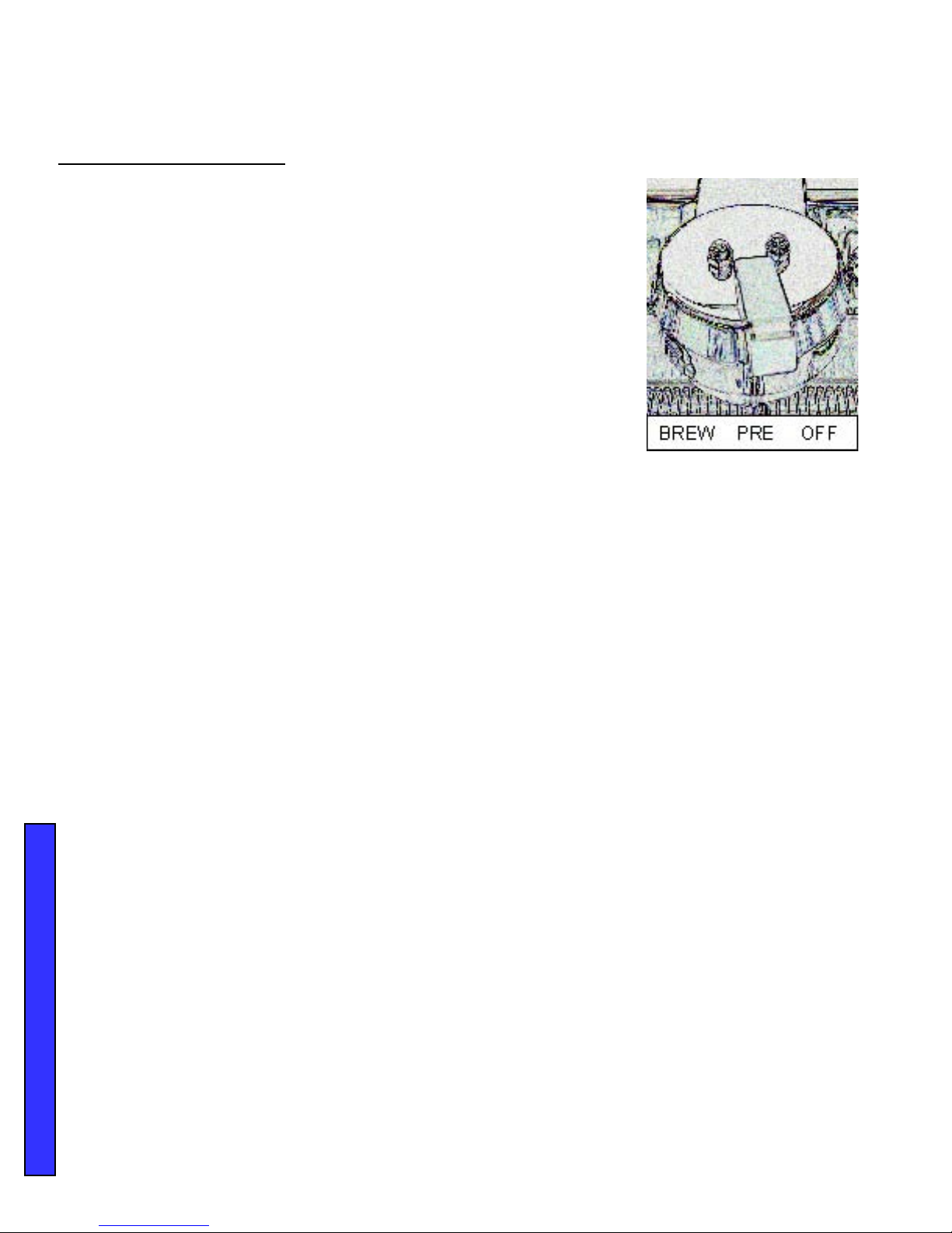
Synesso Espresso Machine User manual

Technical Manual
Synesso™, Inc.
309 S. Cloverdale, C41/ Seattle, WA 98108
tel. 206.764.0600 / fax 206.764.0601

Technical Manual 2
This Service Manual is intended for use by
qualied service technicians only.

Technical Manual 3
Table of Contents
Safety and Tools.............................................Pages 4-5
Installation.......................................................Pages 6-10
Hydraulic System............................................Pages 11-21
Electrical System............................................Pages 22-27
Troubleshooting...............................................Pages 28-35
Periodic Maintenance......................................Pages 36-39
Programming Instructions...............................Pages 40-62

Technical Manual 4
Tools and recommended Items required to fully diagnose, service and
maintain Synesso™ machines
• Multi Meter – reads volts, amps and ohms. The Fluke T5-600 is an excellent tool
• Heat Shrink Gun or Torch
• Vacuum with a Hose
• Compressed Air
• Descaler – Citric Acid
• Flashlight
• Box Knife
• Thread Sealant – Red and Blue Loctite
• Food Grade Grease
• Tube Bender
• Flair Tool - 45°
• Tube Cutter
• Brass Bristle Brush
• Socket Wrench with 1/2” and 9/16” sockets
• Hammer
• Wire Stripper / Crimper
• Small Punch and Chisel
• Small Files – Round and Triangular
• Small Picks – Straight and Curved (great for replacing portalter gaskets)
• Die and Tap, 1/8” NPT and 1/4” NPT
• Tap for Threads, 10 - 32 and 3/8 – 16
• Set of Allen Wrenches – 3/32” is for the brass ow jet, 9/64” for the brew valves, 1/4” for
steam valve seat
SAFETY AND TOOLS
Safety Precautions:
Espresso machines have numerous potential hazards, and it is of paramount importance
to Synesso™ that people servicing our machines take all necessary precautions to ensure
their personal safety. Please note and follow the safety stickers on the machine.
When working on the machine’s boilers (unless otherwise instructed in the directions):
• Turn the machine off and shut off the incoming water supply.
• Depressurize the boilers (the steam boiler can be depressurized by opening both steam
wands, and the coffee boilers can be depressurized by shutting off the water and heat-
ing element breaker and turning the group top to the pre-infuse position.
When working on any electrical wiring (unless checking voltage or amperage readings or
otherwise instructed in the directions) ensure that the machine is switched off at the electri-
cal box and the machine is unplugged.
SAFETY AND TOOLS

Technical Manual 5
• Wrenches: 11/32, 1/4, 5/16, 3/8, 7/16, 1/2, 9/16 , 5/8, 11/16, 3/4, 12mm & 7mm + 1 extra 9/16 and
5/8
• Large, Medium and Small Adjustable Wrenches (Crescent Wrenches)
• Pliers: Channel Lock, Standard and Side Cutters
• Philips Head Screwdrivers: #2 short, #2 long and #1
• Flat Head Screwdrivers: #2 short, #2 medium, #2 long, #1 and large screwdriver to use as a pry
bar
• Pen and paper
• Hand cleaner
• Towels
SAFETY AND TOOLS

Technical Manual 6
Front of machine
View of top of
1 group machine
Foot diameter
3.1cm / 1.25"
Steam handle
7 cm
3"
59 cm / 23"
30 cm / 12"
15 cm
6"
8.5cm
Legend:
X: 1 group: 39.5cm / 16"
2 group: 67cm / 26"
3 group: 94cm / 37"
Y: 1 group: 21cm / 8"
2 group: 48 cm / 19"
3 group: 76cm / 30"
14 cm
5.5"
INSTALLATION DIAGRAM
MACHINE FOOTPRINT
4"
Hole for
hoses
6.5cm / 2.5"
X
Y
Incoming Water
Filtration System
Drain hose
Treated
water to
pump
Water from
pump to groups
Power
to
pump
Mains
power
Water Requirements
Proper water filtration and regular filter changes are a requirement to keep your factory
warranty valid and your machine functioning properly. It is highly recommended that you
contact a professional water filtration specialist in your area and have your water tested
to determine the proper filtration system.It is important to note that many municipalities
change their water sources throughout the year,so periodic water tests may be necessary.
Water Standards to keep your warranty valid:
Total Dissolved Solids (TDS) 30 to 200 ppm (parts per million)
Total Hardness - in ppm Less than 85 ppm
Total Hardness - in grains 3 to 5 grains (divide ppm by 17.1 to get grains)
pH 6 pH to 8 pH
Chloride 0 ppm - any Chlorides can be corrosive and harmful
Total Alkalinity Less than 100 ppm
Chlorine 0 ppm
Iron 0 ppm
Water
to steam
tank
Electrical requirements:
1 Group 110v: 60 hz, 20 amp
1 Group 220v: 50/60 hz, 16 amp
2 Group: 220v, 50/60 hz, 28 amp
3 Group: 220v, 50/60 hz, 36 amp
Hydra Electrical Requirements:
2 Group: 220v, 50/60 hz, 30 amp
3 Group: 220v, 50/60 hz, 40 amp
*Located within 3' of machine
Pump and Motor:
Located within 5' of the machine.
Dimensions: H 6.5"x W 5.5"x D 9.5"
Counter requirements
* Easily cleanable
* Sturdy, level and horizontal
* Capable of sustaining weights up
to 300 lbs.
* 2.5" round hole drilled for hoses
(see "Footprint" for hole location)
* Clearance: 1" behind, 3" in front
Drainage requirements:
Located within 5' of the machine.
Drain hose should run as vertically
away from the machine as possible.
Water requirement
* 3/8" cold water supply line
* Properly treated water required for
warranty (see below for details)
* Shut-off valve
* Located within 5' of the machine
* Braided stainless lines provided
Note: Hydra/hybrid machines have
multiple pumps and motors
INSTALLATION

Technical Manual 7
INSTALLATION
INSTALLATION
To maintain the 1 year warranty, an authorized or certied espresso service representative
must perform the installation of this espresso machine.
Site Preparation
The machine must be placed on a level horizontal surface that can be easily cleaned and is capable
of sustaining a minimum of 300 lbs. of weight.
The surface depth should allow for a minimum clearance of 1” behind and 3” in front of the machine.
Make a 2 ½” round hole through the counter top, 4” from the back center of the machine. This should
provide ample room for the hoses and electrical lines.
A 3/8” cold water supply line with a shut off valve is needed within 5’ of the machine, preferably
located directly underneath the machine.
A proper water ltration or softening system must be installed on the incoming water supply. Water
treatment systems will vary, and it is important to use a system designed to match the needs of your
specic area. Most water ltration systems require periodic maintenance, including cartridge or lter
replacement. This is vital to the proper functioning of the machine and the quality of the espresso
served. Follow the instructions provided by your water treatment system for proper installation.
Note: Improper water ltration can result in water damage inside the machine causing scale and
corrosion. DAMAGE CAUSED BY IMPROPER WATER TREATMENT WILL NOT BE COVERED BY
THE MACHINE WARRANTY.
There must be adequate room under the counter to locate the motor and pump. This should be within
5’ of the cold water supply line. The pump should be easily accessible for potential adjustments and
should have proper ventilation and a minimum of 3” clearance on all sides. Dimensions of the pump
and motor are: 6 ½” Height x 5 ½” Width x 9 ½” Depth.
A oor drain or sink should be readily available. The best location is directly under the installation site
of the machine. The drain hose should descend steeply for proper drainage.
An electrical receptacle and matching plug, rated at the proper voltage and amperage is required
within 3’ of the location of the machine. Plug ends are not included with the machine. Below are the
recommended cord plug ends for the Synesso™ machines:
• 1 Group, 110 V – UL-listed 20 amp
• 1 Group, 220 V – UL-listed 20 amp
• 2 Group, 220 V – UL-listed 30 amp
• 3 Group, 220 V – UL-listed 50 amp

Technical Manual 8
Plumbing Instructions
This equipment is to be installed to comply with the applicable federal, state or local plumb-
ing codes.
Connect the 3/8” compression tting of the provided stainless steel braided hose to the
connection from the ltered, cold water line.
The ¾” inside diameter clear vinyl ribbed hose connects the outlet tting of the drain box to
the drain (located on the right hand, bottom, rear corner). Run this hose to the oor drain or
oor sink.
Fittings on the hoses are 3/8” compression type ttings, thread sealant or Teon tape is not
necessary. Make connections snug, but do not over tighten.
Turn water ON and check for leaks.
NOTE: The Synesso™ requires a minimum of 35 PSI of line pressure to have the steam
tank auto-lling system function properly.
Electrical Instructions
After you make sure your receptacle and circuit are rated for the proper voltage and
amperage (see specications chart on page 9) for your model, install a matching plug on
the power cord provided with the Synesso™ machine.
North American Conguration Outside of North America
Green Ground Green Ground
White 110 V White 220 V
Black 110 V Black Neutral
Make sure that the On/Off electronics switch (red rocker) and the heating element breaker
on the Synesso™ are in the OFF (0) position, then plug the power cord into the receptacle.
IMPORTANT - If the voltage on the receptacle used is less than 210 Volts, it may be nec-
essary to install an in-line Buck-Boost transformer to increase this voltage.
• 1 and 2 Group 220 Volt Machines require a 1.0 KVA transformer
• 3 Group 220 Volt Machines require a 1.5 KVA transformer.
INSTALLATION

Technical Manual 9
Specications for the Synesso™ Line of Semi Automatic Espresso Machines
Model 1 Group 1 Group 2 Group 3 Group
Voltage 110 220 220 220
Hertz 60 50 / 60 50 / 60 50 / 60
Amps - max draw 20 16 28 36
Brew and Steam Specications:
Watts per Element, Steam Tank 1000 1000 x 2 2000 x 2 2500 x 2
Total Steam Element Wattage 1000 2000 4000 5000
Steam Tank Capacity (Liters) 3.2 3.2 7.7 12.3
Watts per Element, Brew Tank 700 700 700 x 2 700 x 3
Brew Tank Capacities (Liters) 1.9 1.9 1.9 x 2 1.9 x 3
Machine Dimensions: Inches / mm Inches / mm Inches / mm Inches / mm
Height (Steam Wand 21”, Handle 20.5”) 18” / 457 18” / 457 18” / 457 18” / 457
Width (Steam Handle to Handle add 3”) 18” / 457 18” / 457 29” / 736 40” / 1016
Depth 23” / 584 23” / 584 23” / 584 23” / 584
Weights & Dimensions: Lbs / Kgs Lbs / Kgs Lbs / Kgs Lbs / Kgs
Machine Weight, Empty 106 / 48 106 / 48 154 / 70 190 / 86
Machine Weight, Full of Water 115 / 52 115 / 52 173 / 77 215 / 98
Shipping Weight (approximate) 175 / 80 175 / 80 225 / 103 270 / 123
Boxed Dimensions: L” x W” x H” 20”x30”x31” 20”x30”x31” 41”x32”x31” 49”x32”x31”
Boxed Dimensions: L x W x H m/m 508x762x787 508x762x787 1042x762x787 1245x813x787
Plumbing (Compression) 3/8” OD 3/8” OD 3/8” OD 3/8” OD
· Certied by ETL for Sanitation to NSF / ANSI Standard 4
· Certied by ETL for Electrical Safety to ANSI / UL Standard 197
· Certied by ETL for Electrical Safety to CSA Standard C22.2 No. 109
· CE Compliant (By request)
· C-Tick Compliant (By request)
INSTALLATION

Technical Manual 10
Start-Up Instructions
1. To ll the coffee brew tanks, turn the water ON.
2. Switch the electronics On/Off switch to ON. This activates
the machine’s water auto-ll feature for the steam tank and
the electronics, but NOT the heating elements.
3. The water level sight glass for the steam tank is located on
the right side of the machine. As the tank lls, the water level
will rise in the sight glass and will automatically stop when
the preset level is reached.
4. Turn the brew group to the BREW position, (see sketch on
the right) allow the air to escape and return the brew group
to the OFF position. Volumetric machines: Activate the
pitcher button on the right side of the keypad. Once the
water ows in a steady stream, press the pitcher button
again to stop the water.
5. Make sure the water level in the sight glass reads at least ½ full and then turn the heating
element breaker to the ON or (1) position.
6. To adjust the pump pressure, activate the pump infusion by turning the brew group to the
BREW position.
7. Locate and read the pump pressure on the brew gauge. The brew gauge is found on the right
hand side of the brew group.
8. Set the pump pressure to 9 Bar. To do this, locate the pump adjusting screw on the right side
of the brass pump housing. Loosen the lock nut and turn screw with a screwdriver.
• Clockwise to INCREASE pressure
• Counterclockwise to DECREASE pressure
9. Please allow at least ½ hour of “warm up” time before using your Synesso™ espresso ma-
chine to brew shots or steam milk. The steam gauge, located on the left side of the rst brew
group, should read a minimum of 1.1 Bar.
Unplugging EMC Compliant Machines
(C-Tick for Australia and NZ, CE for Europe)
To comply with EMC (Electromagnetic Compatibility) regulations, Synesso™ is required to install
a capacitor in the electronics box across the main power IN. To avoid an electric shock from the
charge held in the capacitor, unplug the cord, taking care to NOT touch the metal prongs on
the plug end. Turn the electronics ON/OFF red rocker switch to the ON position and wait a few
INSTALLATION

Technical Manual 11

Technical Manual 12
Hydraulic System
HYDRAULIC SYSTEM
Overview
The hydraulic system in the Synesso™ is comprised of all parts through which water ows
starting with where it enters the machine from the water treatment/ltration system. This
chapter will detail the ow of water and some of the associated electrical componentry.
Water requirements:
Proper water ltration and regular lter changes are a requirement to keep your fac-
tory warranty valid and your machine functioning properly. It is highly recommended
that you contact a professional water ltration specialist in your area and have your water
tested to determine the proper ltration system. Good water treatment systems will remove
tastes and odors as well as particulate matter that can block valves and cause issues with
the machine. Hard water will cause scale to develop inside the machine which adversely
affect the water ow and heating processes, so it is vital to have water hardness in the
recommended range. It is important to note that many municipalities change their water
sources throughout the year, so additional water tests may become necessary.
Water Standards to keep your warranty valid:
Total Dissolved Solids (TDS) 30 to 200 ppm (parts per million)
Total Hardness -(in ppm) Less than 85 ppm
Total Hardness – (in grains per gallon) 3 to 5 grains (divide ppm by 17.1 to get gpg)
pH 6 pH to 8 pH – above 8 is very harmful
Chloride 0 ppm – any Chlorides can be corrosive and harmful
Total Alkalinity Less than 100 ppm
Chlorine 0 ppm
Iron 0 ppm
Synesso™s utilize 3/8” braided stainless hoses (supplied with machine) to connect to the
water treatment system. Once the machine is set up and the water quality is checked, the
machine is ready to be connected to the water treatment system. The water then passes to
the pump and motor.
On single inlet machines, the water then travels through one hose to the machine and sup-
plies both the coffee boiler system and the steam boiler.
On dual inlet machines, the water splits off at the pump: the water for the coffee boiler goes
through the pump and the water for the steam boiler splits off and goes through a separate
line to ll the steam boiler. The next 3 pages show the dual, single, and Hydra inlet water
paths.

Technical Manual 13
HYDRAULIC SYSTEM
HYDRAULIC SCHEMATIC--DUAL INLET

Technical Manual 14
HYDRAULIC SYSTEM
HYDRAULIC SCHEMATIC--SINGLE INLET

Technical Manual 15
HYDRAULIC SCHEMATIC--HYDRA
HYDRAULIC SYSTEM

Technical Manual 16
Pump and Motor:
Synesso™ uses a Fluid-o-tec rotary
vane pump which boosts incoming water
pressure to 9 bar when the motor is acti-
vated. Pressure can be adjusted by loosen-
ing the nut on the right side tting and then
turning the adjustment screw clockwise
(increasing pressure) or counter-clockwise
(decreasing pressure).
Water in
Water to
steam tank
Water to
coffee
tanks
Pump congurations:
Until serial number 356, Synesso™s had
a single inlet conguration as the stan-
dard. After 356, the dual inlet conguration
is the standard. Hydras have a separate
pump and motor per group, therefore all
Hydras come equipped with single inlet
style pumps.
Water Inlet control valves:
Serial numbers 1-340 feature the Skinner-
style valves shown in the upper part of the
picture on the left. These were replaced on
serial number 341 onwards with the Parker
ZB09 for ease of repair or replacement.
Both valve styles feature electronic coils
which, when energized, move a piston
which allows water ow through the valve.
When deactivated, the piston’s presence in
the valve stops the ow of water.
The picture on the next page shows the
steam tank autoll conguration. All 3 of the
water control valves are now Parker ZB09.
Upgrade kits are available through Synes-
HYDRAULIC SYSTEM

Technical Manual 17
Mix valve
adjuster Cold water
valve
Expansion
valve Drain hose
Coffee
inlet hose
(Fill Line)
Steam
tank ll
hose
Brew Tanks
Check valve
Drain box
Steam inlet
check valve
Steam tank
water inlet
valve
Heat Exchanger
Tubes
Pressure Relief
Valve (under hose)
Vacuum breaker
Sight Glass
Hot water
valve
Drain tube
from brew
tanks
Water Inlet Components:
Brew Gauge:
The brew gauge reects pressure in the brewing system. On a standard Synesso™, there is
one gauge for the entire brewing system; on a Hydra, each brew tank has its own brew gauge.
The gauge normally moves between 3-5 bar (resting pressure) to 9 bar (brewing pressure)
and up to 12 bar (expansion pressure) at which point the expansion valve opens and releases
the excess pressure.
Brew Tank Check Valve:
Check valves prevent water from going the wrong way in the hydraulic system. Water ow
should only go one direction and the check valve ensures that pressuized water from inside
the tanks cannot overwhelm the incoming water pressure and go backwards.
Coffee Inlet Fill Line:(Single inlet and Hydra machines would have this line only )
Supplies the brew tanks with water, passing rst through the heat exchangers.
Major Components of the Water Inlet System
Brew gauge
HYDRAULIC SYSTEM
Cyncra prior to 2011

Technical Manual 18
Water Inlet Components (cont.):
Drain box:
Water ows into this box prior to going through the drain hose to the oor drain. It is important
to periodically pour small quantities of hot water down this drain box to clear any build up of
coffee oils inside the box.
Drain Hose:
Waste water and some grounds go down this tube to the drain. It’s important to keep this free
of clogs and maintain a steeply vertical path to the oor drain.
Drain tube from brew tanks:
This copper manifold allows water from the brew valves to discharge safely down the drain
after shots are completed. It also is directly connected to the drain system on the left
hand group, allowing the user to drain the left tank easily after depressurizing the system.
Expansion valve:
The brew tanks are completely saturated with water. As the tanks heat, the pressure increases
within the tank.The expansion valve allows this pressurizing water to release safely into the
drain box. The release point is 12 bar and is adjustable by turning the end of the valve with a
wrench clockwise to increase or counter clockwise to decrease.
Heat Exchanger tubes:
In order to maintain extremely stable brewing temperatures, Synesso™ incorporates heat
exchanger tubes which run from the water inlet side through the steam tank and then go to
each separate coffee boiler. The internal diameter of the heat exchangers are precisely
designed to aid in the energy efciency and thermal stability of the Synesso™.
Cold Water Valve:
Synesso™ has 2 valves which provide water to the Americano (tea) spout: the hot water valve
and the cold water valve. The cold water input allows the user to moderate the temperature at
the spout to make drinks appropriate temperatures for their customers.
Hot Water Valve:
This valve supplies hot water from the steam tank (which is mixed with cold water from the
cold water valve) to the Americano (tea) spout.
Mix Valve Adjuster:
This buttery valve allows the user to increase or decrease the amount of cold water (from the
cw valve above) going to the Americano (tea) spout. Turning this valve completely clockwise
shuts the cold water off, while turning it counter-clockwise allows more cold water in.
Synesso™ sets machines to have a steady ow of water, at approximately 203° F in bench
test.
Pressure Relief Valve (PRV):
The PRV is a safety release for the steam boiler which opens and releases pressure if the
boiler rises above 3.5 bar (50 psi). The PRV is housed inside the yellow tubing which
would direct any releases to the drain box, minimizing spray on the electronic valves.
HYDRAULIC SYSTEM

Technical Manual 19
Water Inlet Components (cont.):
Sight Glass:
Connected to the steam tank by two tubes, the sight glass provides a visual
representation of the level of water in the steam tank. It should be about 1/2 to 2/3 full during
normal operation. This is a safety feature which enables the user to ensure that they have
sufcient water levels in their steam system.
Steam Inlet Check Valve:
See Brew tanks check valve description. (Page 17).
Steam Inlet Water Control Valve:
When the upper level probe detects an absence of water, it sends a signal to the CPU to open
this valve and allow water into the steam tank. The water then lls the tank until the
probe grounds out on the water, and the valve is then closed.
Steam Tank Inlet Fill Line: (Dual inlet machines only)
This is the incoming 3/8” steel braided line which supplies the steam tank with water.
Vacuum breaker:
Allows steam pressure to build above atmospheric pressure. As the element heats the water
in the steam tank, the pressure from the steam pushes an internal rod and o-ring up, sealing
the steam inside the tank. Pressure continues to build until the temperature probes sense
the temperatures are to the set points, then keeps this pressure inside for use in heating
milk, maintaining a hot water supply, and pre-heating the brew water in the heat exchanger
tubes.
HYDRAULIC SYSTEM
2011 2 Group Cyncra Inlet (right) side

Technical Manual 20
Major Components of the Water Outlet (Left) Side
Steam
actuator
rod
1st position brew
tank ll tube
Brew tank
drain tube
Brew tank
Steam shut off valve
Steam
gauge
Steam tank
thermal overload
switches
Upper Level
probe
Heating
element
Low level probe
Steam gauge
tube
Temperature probes
2nd position
brew tank ll tube
1st and 2nd position brew tank ll tubes:
After travelling through the steam boiler, the heat exchangers exit on the left side of the
machine and copper tube (these were stainless steel until serial number 352) deliver the
pre-heated water to the brew tanks.
Brew tank:
Synesso™’s brew tanks are solid stainless steel, welded internally and externally in order to be
leak-proof and thermally stable. Each brew tank has its own isolated system from the water
inlet. This allows the user to set different temperatures on each group, as well as function
without a group in the system if something has gone wrong with a group. There is a 3-way
brew valve which controls the ow of water to the group head.
Brew tank drain tube:
Each group head is tted with a drain tube to easily drain the tank. In order to drain a brew
group, remove the pressure from the brew groups by turning off the water, cycling through the
control panel to the Temperature Display screen on menu level 2. Turn the Brew Valve
setting to ON which will allow a small amount of water to run out of the groups. Once the water
stops, select NORMAL on the Brew Valve control line. Remove the 1/2” plug tting on the end
of the drain and attach a 3/8” rubber line to drain the water into the drain pan. Set the Brew
valve control back to ON to completely drain the tank.
Heating element:
A 2-leg incoloy and stainless steel heating element which provides the heat for the steam
boiler. It is controlled by the thermal probes and will be shut off in the case of over-heating
or low water levels.
HYDRAULIC SYSTEM
Cyncra prior to 2011
This manual suits for next models
1
Table of contents
Other Synesso Coffee Maker manuals

Synesso
Synesso ES.1 User manual

Synesso
Synesso S Series User manual

Synesso
Synesso Cyncra 2016 User manual

Synesso
Synesso MVP User manual

Synesso
Synesso Sabre User manual

Synesso
Synesso Cyncra User manual

Synesso
Synesso MVP User manual

Synesso
Synesso MVP Series User manual

Synesso
Synesso Cyncra User manual

Synesso
Synesso MVP Hydra Assembly instructions