SynQor UPS-1250-270 Series Manual

UninterrUptible power SUpply
UPS-1250-S-1U
UPS-1250-E-2U
1.888.567.9596 (USA only) |SynQor Headquarters 155 Swanson Road, Boxborough, MA 01719-1316 USA |www.synqor.com
N+M Redundancy
(optional)
Operator’s Guide
UPS-1250-270 Series
Made in USA

006-0007290 UPS-1250-270 Rev A 2 of 56 02/16/2022 www.synqor.com
Table of Contents
Section I Warnings
Hazardous Voltages ...................................................................................................................................................4
Hazardous Energies...................................................................................................................................................5
Battery Pack..................................................................................................................................................................6
Protection from the Environment .........................................................................................................................6
No User Serviceable Parts........................................................................................................................................6
Section II General Product Information
Product Description ...................................................................................................................................................7
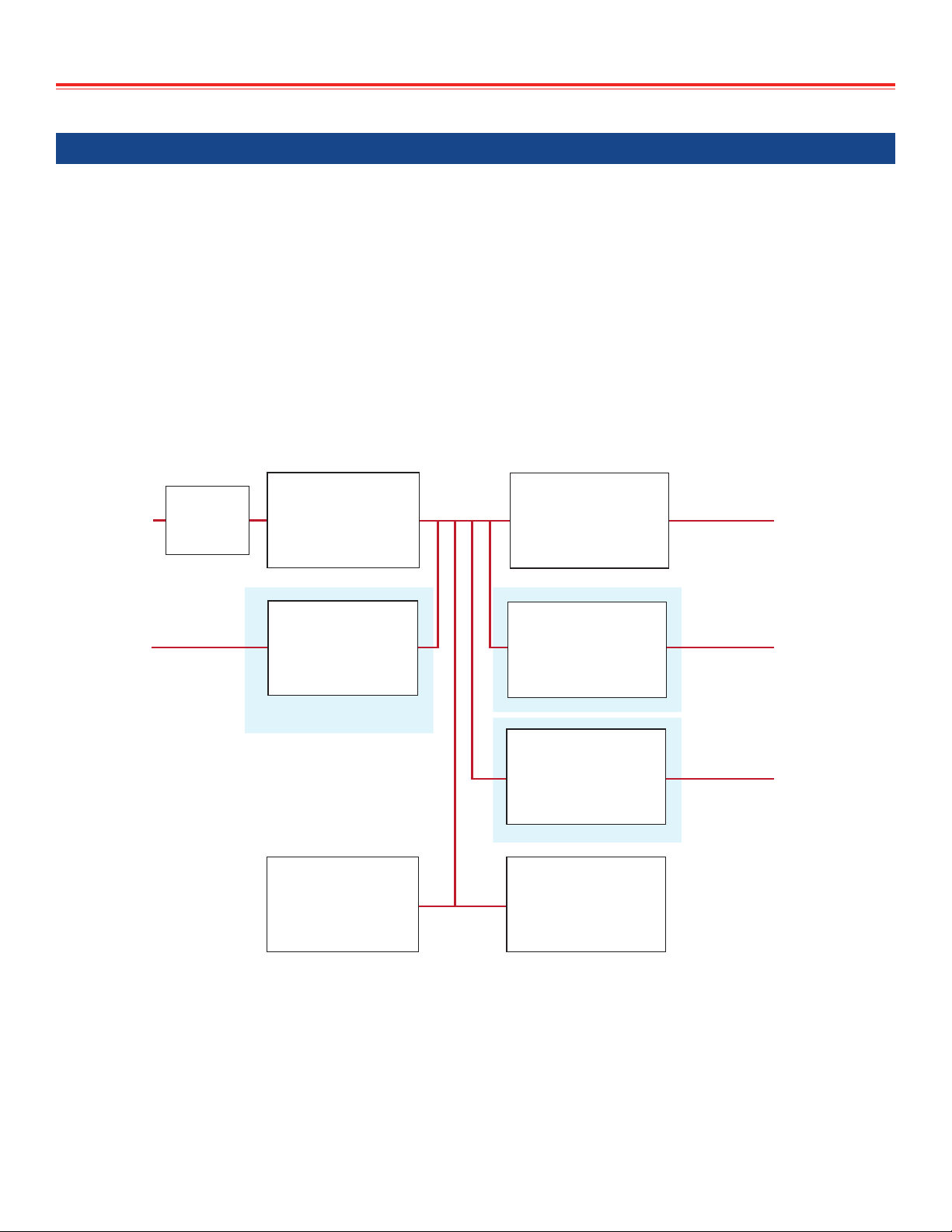
Product Topology ........................................................................................................................................................8
Part Numbering Scheme and Options ................................................................................................................9
Product Specifications............................................................................................................................................ 10
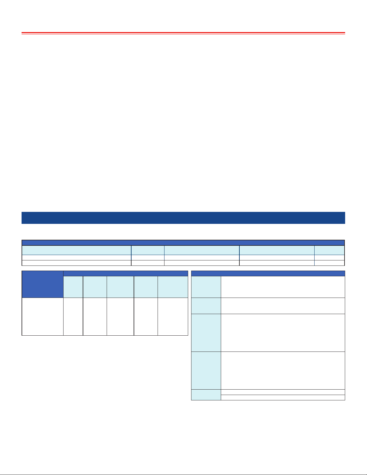
Electrical Characteristics ..................................................................................................................................... 11
1U Mechanical Diagram....................................................................................................................................... 14
2U Mechanical Diagram....................................................................................................................................... 15
UPS Efficiency............................................................................................................................................................ 16
Total Output Power that can be derived from the AC INPUT ................................................................. 16
Power Cable Wiring Diagram ............................................................................................................................. 20
Power Cable Wire Size............................................................................................................................................ 21
Section III Operation
Set-Up ........................................................................................................................................................................... 22
Start-Up ....................................................................................................................................................................... 23
Shut-Down .................................................................................................................................................................. 23
Setting DC3 OUTPUT Voltage and Current ................................................................................................... 24
Power Cable Connections/Disconnections While Operating .................................................................. 26
Cooling System .......................................................................................................................................................... 27
Front Panel Indicators ........................................................................................................................................... 28
LEDs...................................................................................................................................................................... 28
Audible alarm ................................................................................................................................................... 33
Hot Swapping the Battery Pack .......................................................................................................................... 33
Operating Environment......................................................................................................................................... 34

006-0007290 UPS-1250-270 Rev A 3 of 56 02/16/2022 www.synqor.com
Section IV Multiple UPS Configurations
Multiple UPS Configurations ............................................................................................................................... 35
Parallel Connection of Outputs: DC3............................................................................................................... 36
N+M Redundancy - Ideal Diode ............................................................................................................... 36
Configuration Cables ..................................................................................................................................... 36
Parallel Connection of Outputs: DC2............................................................................................................... 37
On/Off Control - Parallel Systems ........................................................................................................... 37
Connection of AC and/or DC INPUTS.............................................................................................................. 38
3-Phase AC INPUT Source .......................................................................................................................... 38
Wiring Caution ......................................................................................................................................................... 39
Section V Battery Pack
Battery Technology.................................................................................................................................................. 40
Electronic Circuitry within the Battery Pack ................................................................................................ 40
Battery Capacity....................................................................................................................................................... 41
Storage of the Battery Pack .................................................................................................................................. 42
Battery Pack Replacement .................................................................................................................................. 42
Handling the Battery Pack................................................................................................................................... 43
Section VI Control Interface Details
Control Cable Connections................................................................................................................................... 44
Internal User I/O Circuits............................................................................................................................. 45
Remote On/Off Switch Connections ......................................................................................................... 45
Digital Input/Output Control Signals............................................................................................................... 46
RS232 Serial Interface............................................................................................................................................ 47
Ethernet Interface.................................................................................................................................................... 48
Section VII Maintenance
Battery.......................................................................................................................................................................... 49
Fans ............................................................................................................................................................................... 49
Cleaning....................................................................................................................................................................... 49
Section VIII Trouble-Shooting Guide
Fault Conditions ....................................................................................................................................................... 50

Section I Warnings
006-0007290 UPS-1250-270 Rev A 4 of 56 02/16/2022 www.synqor.com
Section I Warnings
Hazardous Voltages
The INPUT AND OUTPUT POWER connectors and cables of the SynQor UPS may have
voltages that are unsafe. INJURY OR DEATH ON CONTACT may result. Appropriate safety
precautions should be taken. All connections should be made in accordance with LOCAL
ELECTRICAL CODES.
• The UPS CHASSIS should be connected to earth or system ground with Ground Stud on the
rear panel, see mechanical diagrams.
• For the AC INPUT cable and connector:
Do not assume that a hazardous voltage is not present at the terminals of the AC input
Do not make contact with the terminals of the AC input connector.
Always connect the cable to the UPS before it is connected to the source of AC power.
from the UPS.
If the AC input cable is connected to the source of AC power and not connected to the UPS,
do not contact the exposed terminals of the AC input cable.
Do not assume that the source of AC power is not present.
Connections between the AC input cable and the source of AC power should not be
accessible.
• For the DC3 OUTPUT cable and connector:
Do not assume that a hazardous voltage is not present at the terminals of the DC3 OUTPUT
Do not make contact with the terminals of the DC3 OUTPUT connector.
Connect the DC3 OUTPUT cable to the UPS before the UPS is turned on.
• For the DC INPUT cable and connector (if present):
The rated DC input voltage of the UPS is below the level considered hazardous.
The DC input terminals of the UPS are isolated from the AC input and DC3 OUTPUTs with
However, never assume the terminals of the DC input connector or the wires of the DC input
cable are safe to contact, even if the UPS or DC input source appears to be o.

Section I Warnings
006-0007290 UPS-1250-270 Rev A 5 of 56 02/16/2022 www.synqor.com
• For the DC1 and DC2 cable and connectors (if present):
The rated DC output voltage of the UPS is below the level considered hazardous.
The DC output terminals of the UPS are isolated from the AC input and DC3 OUTPUTs with
However, never assume the terminals of the DC output connector or the wires of the DC
• For the BATTERY PACK (if not inserted into the UPS):
considered hazardous.
damage internal control circuitry.
Hazardous Energies
The INPUT AND OUTPUT POWER connectors and cables of the SynQor UPS may be the source
of high levels of energy. Do not inappropriately make electrical contact between any terminal of
a connector and another, or between any wire of a cable and another, or between any terminal
DAMAGING ELECTRICAL ARCS may result. Care should
be taken to avoid accidental electrical contacts of this sort.
When the BATTERY PACK
power pins or between any power pin and ground should therefore not be damaging. However,
care should take to avoid accidental electrical contacts of this sort.

Section I Warnings
006-0007290 UPS-1250-270 Rev A 6 of 56 02/16/2022 www.synqor.com
Section I Warnings
Baery Pack
The individual LITHIUM POLYMER BATTERIES
they should not be physically, thermally or electrically abused.
The TRANSPORT
DISPOSED
or RETURNED
at the following link: http://www.SynQor.com/UPS/documents/Contact.pdf. Please contact
eyes. It may be toxic.
page 42.
Protecon from the Environment
THESE LEVELS SHOULD NOT BE EXCEEDED.
Do not obstruct the air intake in the front of the UPS or the fan exhausts in the rear panel of the
No User Serviceable Parts
The SynQor UPS has no user serviceable parts inside of it. DO NOT REMOVE the cover of the
UPS or any of its connectors. DO NOT OPEN
should perform repairs.

006-0007290 UPS-1250-270 Rev A 7 of 56 02/16/2022 www.synqor.com
Section II General Product Information
Product Descripon
power when other power sources are not present.

Section II General Product Information
006-0007290 UPS-1250-270 Rev A 8 of 56 02/16/2022 www.synqor.com
Product Topology
and outputs.
AC
INPUT
DC
INPUT
DC2
OUTPUT
FIXED
DC1
OUTPUT
FIXED
DC 3
OUTPUT
ADJUSTABLE
AC to DC
w/ PFC
and
ISOLATION
BATTERY
with
CHARGER
and
ELECTRONIC SWITCH
(OPTIONAL)
(Not available with DC2 Option)
ELECTRONIC
SWITCH
ISOLATED
DC-DC
CONVERTER
BULK ENERGY
STORAGE
CAPACITOR
ISOLATED
DC-DC
CONVERTER
(OPTIONAL)
(OPTIONAL)
ISOLATED
DC-DC
CONVERTER
CIRCUIT
BREAKER

Section II General Product Information
006-0007290 UPS-1250-270 Rev A 9 of 56 02/16/2022 www.synqor.com
output voltage.
circuitry to avoid damage due to improper charging or discharging, or to excessive temperatures.
Part Numbering Scheme and Opons
Base Models
Model Number Power Battery Run-Time Height (W x D x H) Weight
@Full Power (80% Power)
UPS-1250-S-1U (1 Standard Battery Pack) 1250 W >10 min. (>13 min.) 1U (17.00” x 21.60” x 1.73”) 32 lbs.
UPS-1250-E-2U (1 Extended Battery Pack) 1250 W >24 min. (>31 min.) 2U (17.00” x 21.60” x 3.33”) 50 lbs.
Base Models
Options Options
AC
Input
Freq
DC3
OUTPUT
DC Input
/ DC2
Output
DC1
Output
Additional
Options
AC input
Freq
L47-65 HZ
W47-800 Hz
UPS-1250-S-1U-
UPS-1250-E-2U-
L
W
S 00
-E 00
DC3
OUTPUT 270 270V Default, 25-325 VdcD 12
M 15
270 P 24
DC Input /
DC2 Output
SNot Installed
R 28 D DC Input
V 40 M DC2 Out 24 VDC with Droop Share
W 50 PDC2 Out 24 VDC No Share
RDC2 Out 28 VDC with Droop Share
Not all combinations make valid part numbers, contact SynQor for availability. VDC2 Out 28 VDC No Share
See the Product Summary web page for more options. WDC2 Out 50 VDC No Share
DC1 Output
00 None
Examples: 12 12 V
15 15 V
UPS-1250-S-1U-L270D50-E00, UPS-1250-E-2U-W270M28-E00 24 24 V
28 28 V
40 40 V
50 50 V
Additional
Options
-E Ethernet/SNMPwithCongurationLoading
00 No CE Marking

Section II General Product Information
006-0007290 UPS-1250-270 Rev A 10 of 56 02/16/2022 www.synqor.com
in the table:
Product Specicaons
http://www.synqor.com/UPS.

Section II General Product Information
006-0007290 UPS-1250-270 Rev A 11 of 56 02/16/2022 www.synqor.com
Electrical Characteriscs
INPUT CHARACTERISTICS
Operating AC Input
Voltage 80-265 Vrms*
Frequency 47-65 Hz
(47-800 Hz Optional)
Input Power Factor >0.98 at 47-65 Hz
>0.97 at 400 Hz
>0.93 at 800 Hz
Maximum Input Current Continuous 20 A (full load, 85 Vrms)
AC Input Circuit Breaker Rating 25 A
(* Power Derating to 80% below 90 Vrms)
Operating DC Input (Optional)
Voltage 22-33 V
Continuous Maximum Input Current 62 A (full load, 22 V)
Transient Maximum Input Current 75 A
OUTPUT CHARACTERISTICS
Total Output Power Continuous 1250 W
Maximum DC3 OUTPUT Power 1250 W
Maximum DC2 Output Power 1250 W
Maximum DC1 Output Power 510 W
(Note: Available DC3 power is reduced by power delivered to DC2 and DC1)
DC 3 Output (Adjustable)
Voltage Range 25 - 325 V
Voltage Setpoint (Default) 270 V
Voltage Setpoint Accuracy ± 3%
Voltage Setpoint Resolution 1 V
VoltageRegulation(OverLoad&Temperature) ± 5%
Current limit Range (User Adjustable) 0 - 6.0 A
CurrentLimitResolution 4 mA
CurrentLimitAccuracy ± 50 mA
Short Circuit Protection Trip Current 20 A
Maximum Output Capacitance 18 mF
DC1 Output (Optional, Fixed)
VoltageRegulation(OverLoad&Temperature) ± 3%
Common Voltage/Power combinations (DC1) 12 V at 42 A =504 W
(Other Options Available) 15 V at 34 A =510 W
24 V at 21 A =504 W
28 V at 18 A =504 W
40 V at 12.5 A =500 W
50 V at 10 A =500 W
DC2 Output (Optional, Fixed)
Voltage Setpoint ± 3%
No Sharing
VoltageRegulation(OverLoad&Temperature) -2%
Common Voltage/Power combinations (DC2) 50 V at 20 A =1000 W
24 V at 50 A =1200 W
28 V at 44.6 A =1250 W
Droop Share (Output droops vs. load to allow passive sharing among modules.)
24 V Option
VoltageRegulation(OverLoad&Temperature) -15%
26 V at 0 A
22 V at 50 A =1100 W
28 V Option
VoltageRegulation(OverLoad&Temperature) -13%
30 V at 0 A
26 V at 48.1 A =1250 W
Specicationssubjecttochangewithoutnotice.
ENVIRONMENTAL CHARACTERISTICS MIL-STD-810G
Temperature Methods 501.5, 502.5
Operating Temperature -20 °C to +55 °C
Non-operating Temperature -40 °C to +65 °C
Altitude Method 500.5
Operating 0 - 18,000 ft
Non-operating 0 - 40,000 ft
Environmental Tests
Shock/Drop Method 516.6, Procedures 1,4,6
Temperature Shock Method 503.5, Procedure 1
Vibration Method 514.6, CAT 5, 7, 8, 9, 24
Fungus Method 508.6
Salt Fog Method 509.5
Sand and Dust Method 510.5, Procedures 1,2
Rain Method 506.5 Procedure 1
Humidity Method 507.5 Procedure 2
Mechanical Vibrations of Method 528 Procedure 1
Shipboard Equipment
RELIABILITY CHARACTERISTICS MIL-HDBK-217F
MTBF 100 kHrs MIL-217FGroundBenign,Ta=25°C
ELECTROMAGNETIC CAPABILITY MIL-STD-461F
CE101 30 Hz - 10 kHz
CE102 10 kHz - 10 MHz
CS101 30 Hz - 150 kHz
CS106 10kHz-40GHz
CS114 10 kHz - 200 MHz
CS116 10 kHz - 100 MHz
RE101 30 Hz - 100 kHz
RE102 10kHz-18GHz
RS101 30 Hz - 100 kHz
RS103 2MHz-40GHz
MECHANICAL CHARACTERISTICS
1U Standard Battery Pack Chassis
Chassis Size 17.00”W x 21.60”D x 1.73”(1U)H
Case Material Aluminum
Total Weight 32lbs.(withchassis&battery)
Optional 2U Extended Internal Battery Pack
Chassis Size 17.00”W x 21.60”D x 3.33”(2U)H
Case Material Aluminum
Total Weight 50lbs.(withchassis&battery)
Connectors
AC Input Connector MS3470L14-4P
User I/O Ports HD DB15 Female
CongurationI/OPort HD DB15 Male
Ethernet Port Amphenol RJF22N00, Code B
DC Input Connector MS3470L18-8P
DC1 Output Connector MS3470L14-4SW
DC2 Output Connector MS3470L18-8S
DC3 OUTPUT Connector MS3470L14-4S
Cooling Exhaust Fans
SoundPressureLevel(SPL) 54 dB(A)
Air Flow 0.67(m3/min) 23.7 CFM
Two fans in system, above specs are for each fan separately.

Section II General Product Information
006-0007290 UPS-1250-270 Rev A 12 of 56 02/16/2022 www.synqor.com
DC2
Output
Option
UPS-1250-S-1U DC3 with DC1 Output/DC2 Output Option
DC1
Output
Option
DC1
Output
Option
Ethernet
Port
Ethernet
Port
DC3
Output
DC3
Output
Exhaust
Fan
Exhaust
Fan
Exhaust
Fan
Exhaust
Fan
I/O
Port
I/O
Port
User
Config
Port
User
Config
Port
Ground
Stud
(1/4-20)
Ground
Stud
(1/4-20)
DC
Input
Option
AC
Input
AC
Input
AC
Circuit
Breaker
AC
Circuit
Breaker
UPS-1250-S-1U DC3 with DC Input/DC1 Output Option
Air intakes
Status Indicator Panel
Status LED
On/Off
17.00"
1.73"
1U
UPS-1250-S-1U

Section II General Product Information
006-0007290 UPS-1250-270 Rev A 13 of 56 02/16/2022 www.synqor.com
3.33"
2U
DC2
Output
Option
UPS-1250-E-2U DC3 with DC1 Output/DC2 Output Option
DC1
Output
Option
DC1
Output
Option
Ethernet
Port
Ethernet
Port
DC3
Output
DC3
Output
Exhaust
Fan
Exhaust
Fan
Exhaust
Fan
Exhaust
Fan
I/O
Port
I/O
Port
User
Config
Port
User
Config
Port
Ground
Stud
(1/4-20)
Ground
Stud
(1/4-20)
DC
Input
Option
AC
Input
AC
Input
AC
Circuit
Breaker
AC
Circuit
Breaker
UPS-1250-E-2U DC3 with DC Input/DC1 Output Option
Status Indicator Panel
Status LED
UPS-1250-E-2U
Air intakes
On/Off
17.00"

Section II General Product Information
006-0007290 UPS-1250-270 Rev A 14 of 56 02/16/2022 www.synqor.com
.750"
[19.05]
.750"
[19.05]
9.750"
[247.65]
18.700"
[474.98]
19.450"
[494.03]
.313"
[7.9502]
.625"
[15.875]
.55"
[13.97]
UNIT
MOUNTING
HOLES
8-32 .250" [6.35]
x26
1.73" [43.942]
1.50" [38.1]
21.60"
[583.64]
17"
[431.8]
MADE IN USA
UPS
POWER OUT
POWER IN
LOAD
CHARGE
FAN
BATT
BATTUPS
ON
OFF
1U Mechanical Diagram
Note:
1)ALLDIMENSIONSININCHES[mm]
TOLERANCES:X.XXIN+/-0.02[0.5]
X.XXXIN+/-0.010[0.25]

Section II General Product Information
006-0007290 UPS-1250-270 Rev A 15 of 56 02/16/2022 www.synqor.com
MADE IN USA
UPS
POWER OUT
POWER IN
LOAD
CHARGE
FAN
BATT
BATTUPS
ON
OFF
3.33"
[84.582] 1.749"
[44.4246]
2.062"
[52.3748]
2.375"
[60.325]
.750"
[19.05]
.750"
[19.05]
9.750"
[247.65]
21.60"
[583.64]
18.700"
[474.98]
19.450"
[494.03]
UNIT
MOUNTING
HOLES
8-32 .250"
[6.35]
x52
.313"
[7.9502]
.625"
[15.875]
.55"
[13.97]
1.50" [38.1]
17"
[431.8]
2U Mechanical Diagram
Note:
1)ALLDIMENSIONSININCHES[mm]
TOLERANCES:X.XXIN+/-0.02[0.5]
X.XXXIN+/-0.010[0.25]

Section II General Product Information
006-0007290 UPS-1250-270 Rev A 16 of 56 02/16/2022 www.synqor.com
UPS Eciency
70.0%
75.0%
80.0%
85.0%
90.0%
95.0%
0 200 400 600 800 1000 1200 1400
Efficiency
Ouput Power (Watts)
Efficiency vs. Output Power
for Each Input Source
28 Vdc
230 Vac
115 Vac
Figure 1
Total Output Power that can be derived from the AC INPUT
power that the UPS can derive See Figure

Section II General Product Information
006-0007290 UPS-1250-270 Rev A 17 of 56 02/16/2022 www.synqor.com
0
200
400
600
800
1000
1200
1400
25 30 35 40 45 50 55
Output
Power
(Was)
Air Temperature (°C)
UPS Output Power vs. Air Temperature
VAC(IN) >105 VRMS or VDC(IN) >22 V or
power drawn from the baery
VAC(IN) = 90 VRMS and VDC(IN) <22 V and
power not drawn from the baery
VAC(IN) = 80 VRMS and VDC(IN) <22 V and
power not drawn from the baery
Figure 2
ooF) without
then the total output power that can be
(except for at the high end of the ambient temperature range – see below). For example, the
ooF). If the total output power is
ooF),
ooooF). For example, the total output power that could
ooF). A higher output power than this would cause the UPS

Section II General Product Information
006-0007290 UPS-1250-270 Rev A 18 of 56 02/16/2022 www.synqor.com
the ambient temperature
oo
ooooF).
derated, as shown in the graph below.
1100W
0
200
400
600
800
1000
1200
1400
60 80 100 120 140 160 180 200 220 240 260 280
Output
Power
(Was)
Input Voltage (Vrms)
Output Power vs. AC Input Voltage
(without switching over to the DC input or the baery)
Steady state
15s transient
2s transient
132V
Figure 3
.

Section II General Product Information
006-0007290 UPS-1250-270 Rev A 19 of 56 02/16/2022 www.synqor.com
Limited by
Pmax
Figure 4

Section II General Product Information
006-0007290 UPS-1250-270 Rev A 20 of 56 02/16/2022 www.synqor.com
Looking at the rear panel, the UPS connector terminals have the following functions and locations:
AC INPUT
A
B
C
D Ground
A
B
D
C
DC INPUT
Return
A
BG
H
DE
CF
DC3 OUTPUT
AReturn
BOUT
C
D Ground
A
BD
C
DC1 OUTPUT
OUT
Return
A
B
D
C
DC2 OUTPUT
OUT
Return
A
HFC
B G
DE
This manual suits for next models
2
Table of contents
Other SynQor UPS manuals